- Home
- Product Categories
- Wireless and IoT
- GE865 Breakout

GE865 Breakout
Replacement: None. We no longer carry this particular breakout or module but check out the cellular category for more cellular modules and evaluation boards. This page is for reference only.
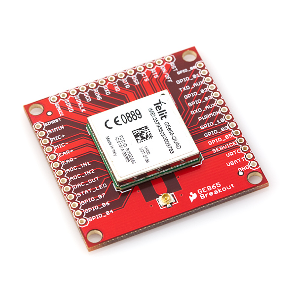
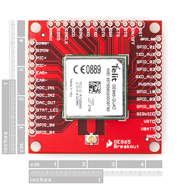
This is a breakout board for the new Telit GE865 Quad cell module. The board comes with the module installed, as well as a U.FL antenna connector. Standard 0.1" spaced headers allow easy access to a full range of functionality. Just connect your power supply (3.22-4.5VDC, 3.8VDC nominal), SIM card, antenna, serial connection and a power button and you're off and running!
The new GE865 product family introduces the smallest GSM/GPRS Ball-Grid-Array (BGA) modules in the market. The low profile and small size of the unique BGA package for the GE865-QUAD enable the design of very compact applications. Since connectors are eliminated, the solution cost is significantly reduced compared to conventional mounting.
With its ultra-compact design and extended temperature range, the Telit GE865 product line is the perfect platform for high-volume M2M applications and mobile data devices. Additional features such as integrated TCP/IP protocol stack and serial multiplexer extend functionality of the application at no additional cost.
State-of-the-art ADCs, DACs and GPIOs provide connectivity to external peripherals such as sensors and displays.
- 1.8x1.8" (45.7x45.7mm)
- Schematic
- Dimensional Drawing
- Telit GE865 documentation (hardware guide, AT command set, etc.)
Comments
Looking for answers to technical questions?
We welcome your comments and suggestions below. However, if you are looking for solutions to technical questions please see our Technical Assistance page.
Customer Reviews
No reviews yet.
Do you have the .brd files for this part? I'm curious what the traces look like for the antenna connector. Thanks
Any hints on how to route to the antenna pads in Eagle? I assume that the outer (ground) ring is ignored, and the center pin 'just flows' when it's assembled? Can you supply either the .brd file, or a pic of the antenna area on the PCB? Thanks!
Do you plan to make the eagle board files available ?
beware that while the module requires ~3.8v to operate, the I/O pins are only 3v tolerant (2.8v really)! You'll likely need to do some level shifting and order a 2.8v regulator from somewhere to interface this to most PICs.