- Home
- Product Categories
- Audio
- SparkFun Analog to Digital Stereo Converter Breakout - PCM1803A

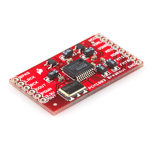
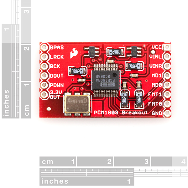
SparkFun Analog to Digital Stereo Converter Breakout - PCM1803A
The PCM1803A is a high-performance, low-cost, 24-bit stereo analog-to-digital converter that can sample as high as 96k. The PCM1803A is a great choice for a wide variety of applications where high performance is necessary. Such applications include AV amplifier receivers, CD recorders, electrical musical instruments, and high precision analog measurements.
Communication with the PCM1803A is achieved through a serial interface called I2S, described in the datasheet below. Both master and slave communication modes are supported and four data formats are available. As recommended by the datasheet, the AGND and DGND are connected directly under the chip via a solder jumper.
This board includes a number of the necessary components you'll need to get the PCM1803A up and running. Both 5V and 3.3VDC regulators are included to power the analog and digital sides, respectively. A 24.576MHz oscillator is included, allowing the PCM1803A to run at a number of different sampling frequencies. All pins of the PCM1803A are broken out to a pair of 0.1" pitch headers, including a 3.3V output pin from the regulator.
- 24-Bit Delta-Sigma Stereo A/D Converter
- Single-supply operation: 5-12VDC input on breakout board
- Oversampling Decimation Filter:
- Oversampling Frequency: ?64, ?128
- Pass-Band Ripple: ?0.05 dB
- Stop-Band Attenuation: -65 dB
- On-Chip High-Pass Filter: 0.84 Hz (44.1 kHz)
- High-Performance:
- THD+N: -95 dB (Typically)
- SNR: 103 dB (Typically)
- Dynamic Range: 103 dB (Typically)
- Sampling Rate: 16 kHz to 96 kHz
- System Clock: 256 fS, 384 fS, 512 fS, 768 fS
- PCM Audio Interface:
- Master/Slave Mode Selectable
- Data Formats:
- 24-Bit Left-Justified
- 24-Bit I2S
- 20-, 24-Bit Right-Justified
- Board: 1.40x0.80"
SparkFun Analog to Digital Stereo Converter Breakout - PCM1803A Product Help and Resources
Core Skill: Soldering
This skill defines how difficult the soldering is on a particular product. It might be a couple simple solder joints, or require special reflow tools.
Skill Level: Noob - Some basic soldering is required, but it is limited to a just a few pins, basic through-hole soldering, and couple (if any) polarized components. A basic soldering iron is all you should need.
See all skill levels
Core Skill: Programming
If a board needs code or communicates somehow, you're going to need to know how to program or interface with it. The programming skill is all about communication and code.
Skill Level: Rookie - You will need a better fundamental understand of what code is, and how it works. You will be using beginner-level software and development tools like Arduino. You will be dealing directly with code, but numerous examples and libraries are available. Sensors or shields will communicate with serial or TTL.
See all skill levels
Core Skill: Electrical Prototyping
If it requires power, you need to know how much, what all the pins do, and how to hook it up. You may need to reference datasheets, schematics, and know the ins and outs of electronics.
Skill Level: Rookie - You may be required to know a bit more about the component, such as orientation, or how to hook it up, in addition to power requirements. You will need to understand polarized components.
See all skill levels
Comments
Looking for answers to technical questions?
We welcome your comments and suggestions below. However, if you are looking for solutions to technical questions please see our Technical Assistance page.
Customer Reviews
No reviews yet.
Fromthe specssheet I read that this device comply to TTL standard, so it can be interfaced with 0/5V logic levels, but the digital suppply is 3.3V. Can you confirm the device need no voltge converters for use with a 5V MCU?
What about a 3.3V MCU?
Thanks
Not breadboard friendly, too wide.
Hi everyone, Does anyone try to use PCm1803A with Arduino uno, is tehre any code example? Is there any way to interface I2S with Arduino UNO?
Thanks in Advance!
Please add an output for the MCLK (oscillator) as well because most of the audio DAC's require it as a system clock anyway though it's not part of I2S specification (the ones which don't need MCLK are for an example the older TDA1543, TDA1387T and TDA1541A DACs, and from the more recent ones the PCM51xx which containins a PLL). With other DACs there is a requirement that the bit clock and L/R clock must be synhronous to the system clock (ESS9023 is an exception and can be used asynchronously).
The 24.576MHz oscillator is suited to certain frequencies--32KHz, 48KHz, 64KHz, 96KHz. Unfortunately, it isn't suited to CD-rate audio, 44.1KHz, which is quite common. Since it can do both higher-quality and lower-quality audio, this may not be an issue for most people, but it's something to be aware of. The clock pins are not among those broken out to the breadboard-friendly connectors.
anyone tried to register this board (as a sound input) in ALSA under Linux??? an especial driver to do this??
Does anyone know of a solution to convert analog audio to digital and to store it on a flash drive in some sort of high-quality format.
I'm looking for something that can record up to as much audio as I can fit on the compact flash drive.
It needs to be really high quality digital.
I envision something that takes a 1/8" stereo input, captures the analog audio coming in, converts it to digital and saves it to the flash drive.
The VS1053 can take in audio and encode it to MP3 and other formats, see the datasheet for details. To the best of my knowledge none of us have actually used it in this capacity, so that's all I know, but let us know how it works if you try it out!
Hopefully someone can help me here... so I think I got this device to spew-out some audio. I hooked-it up to a PIC18F4620 and the PIC is generating a 2.5MHz PWM 50% duty and the output of the PCM1803 is showing me what seems like the proper data.... but now... how can I listen to it? I believe that it is PCM data that can be directly piped into an S/PDIF input on an A/V receiver (which I don't currently have)... is that true? Otherwise, I'm somewhat confused as to how I would be able to lower the quality to have the lowest bitrate so that I could save it somewhere then afterwards manipulate the data... any input anyone? Thanks!
Just an FYI for anyone wanting this chip for accurate time-domain A/D. I have tried this and learnt the following the hard way:
Figure 3 on Pg 6 of the datasheet -> it's digital antialias filter rolls off too late. In practice I've found inexplicable errors up to half the sensitivity of the device if any input is in the 0.45 to 0.5 fs range. Theoretically it shouldn't downmix aliasing signals here onto 0 Hz, but it does. I can even get it to hold a constant (0 Hz) offset by feeding it a strong sinewave at 0.5 fs.
If you want to use this to make accurate time-domain measurements from sensors, then it very badly needs a Bessel analog anti-alias filter just before its input, to ensure there isn't any noise in that deadly 0.45 - 0.5 fs band. There are some ok switched-cap filter chips for this - a break out would be nice. Integrating both so that the switched cap filter runs at the same clock as this chip would be better.
Otherwise, you can use a low-order filter at far less than 0.5 fs, so that the roll-off by then is decent, and then implement a multirate filter on the data afterwards. This can get you better accuracy, since switched-cap filters aren't all that good for low noise measurements. The expense is only getting a sample ~ 1kHz or so, But this still gives a hell of a much cleaner signal, which can then be used in feedback loop control of some high power actuator without making everything go haywire.
If you don't put the anti-alias filter in, there's nothing you can do afterwards to get rid of the noise - it ends up aliased all across the passband, and makes the "24-bit" precision a joke.
You can still get away without an anti-alias filter, if you use, say, a completely faraday-shielded sensor. (like a vibration sensor or microphone) and never let any radio interference at all onto the wire. But as soon as you arn't shielding up to very high frequencies, your noise will come back.
I'd really like to see a breakout board with I2C interface, and integrated antialias filtering. The filter can easily be variable so as to match the sample rate if it's a switched-cap type. 14 bits would be more than enough (accuracy limited by the switched-cap filter). A sigma delta converter with an overall bessel response and a digital multi-rate filter would be very very nice for getting very clear time-domain samples. Would make sonar easy. Problem is no-one designs chips like this with flat pass-band group delay in mind.
How do you listen to the audio the device sends you? How do you confirm your data is good? See my message below...
I Strongly agree! I would love to see a 16bit or higher time-domain A/D for fast and accurate sensor measurement. One properly filtered channel with serial interface (I2C, I2S, TTL, etc) would be just fine. The (more than) order of magnitude increase in speed and accuracy over a pic or atmega ADC would serve as a great input for a PID loop, etc. You could build a pretty decent balancing bot with that.
I am trying to interface PCM1803a breakout card to Arduino UNO as SPI slave. i.e.PCM1803a (master), Arduino (slave). My configurations are FMT0 : 0, FMT1 : 0, MODE0: 1, MODE1: 0. How to select the sampling frequency (fs) of PCM1803a.
Thanks in Advance.
Now, could I use this instead for analog video? or would that just plain not work?
I know SFE carries an IC that does that, but this would be a little easier to use, for it's size... I guess I could just make a little BOB for the IC.
I wanted to second the suggestion of Botmaster. Any chance this board could be used as a fast analog input and if so does anyone have a sketch demonstrating such an application? Alternatively, does anyone have a solution to acquire analog signals faster than analogRead() through the I2C bus?
Asking questions are a good way of finding things out. I would have never come across this device!
Are there any plans to make a similar product, but for sensor analog signals, and with more input channels( from what I've read, it has only 2 inputs now)?
It looks like a good basis for an ADC breakout board
wut?