- Home
- Product Categories
- Monochrome
- Serial Enabled 16x2 LCD - Black on Green 5V

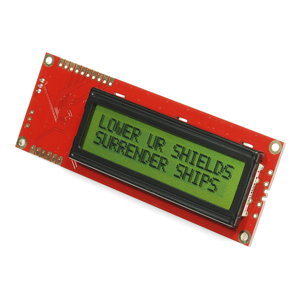
Serial Enabled 16x2 LCD - Black on Green 5V
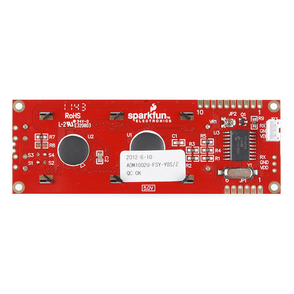
This is the latest evolution of our serial LCD. Included on a single board is a 16x2 LCD and an embedded circuit based around a PIC 16F88. The on-board PIC takes a TTL serial input and prints the characters it receives onto the LCD. The installed firmware also allows for a number of special commands so you can clear the screen, adjust the backlight brightness, turn the display on/off, and more.
Communication with SerLCD requires 5V TTL serial at a default baud rate of 9600bps (8-N-1). You can adjust the baud to any standard rate between 2400 and 38400bps. The power (VDD), ground (GND) and RX pins are all broken out to both a 0.1" pitch header as well as a 3-pin JST connector.
SerLCD has the ability to dim the backlight to conserve power if needed. There is also a potentiometer on the back of the display to adjust the contrast.
This LCD makes for a great gift, because it can be used for so many different projects! For more gift ideas check out the SparkFun Gift Guide!
- Embedded PIC 16F88 utilizes onboard UART for greater communication accuracy
- Adjustable baud rates of 2400, 4800, 9600 (default), 14400, 19200 and 38400
- Operational Backspace
- Greater processing speed at 10MHz
- Incoming buffer stores up to 80 characters
- Backlight transistor can handle up to 1A
- Pulse width modulation of backlight allows direct control of backlight brightness and current consumption
- All surface mount design allows a backpack that is half the size of the original
- Faster boot-up time
- Boot-up display can be turned on/off via firmware
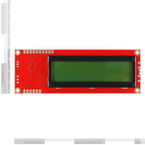
- User definable splash screen* PCB: 103x36mm
- LCD: 71.4x26.4mm
Serial Enabled 16x2 LCD - Black on Green 5V Product Help and Resources
Core Skill: DIY
Whether it's for assembling a kit, hacking an enclosure, or creating your own parts; the DIY skill is all about knowing how to use tools and the techniques associated with them.
Skill Level: Noob - Basic assembly is required. You may need to provide your own basic tools like a screwdriver, hammer or scissors. Power tools or custom parts are not required. Instructions will be included and easy to follow. Sewing may be required, but only with included patterns.
See all skill levels
Core Skill: Programming
If a board needs code or communicates somehow, you're going to need to know how to program or interface with it. The programming skill is all about communication and code.
Skill Level: Rookie - You will need a better fundamental understand of what code is, and how it works. You will be using beginner-level software and development tools like Arduino. You will be dealing directly with code, but numerous examples and libraries are available. Sensors or shields will communicate with serial or TTL.
See all skill levels
Core Skill: Electrical Prototyping
If it requires power, you need to know how much, what all the pins do, and how to hook it up. You may need to reference datasheets, schematics, and know the ins and outs of electronics.
Skill Level: Competent - You will be required to reference a datasheet or schematic to know how to use a component. Your knowledge of a datasheet will only require basic features like power requirements, pinouts, or communications type. Also, you may need a power supply that?s greater than 12V or more than 1A worth of current.
See all skill levels
Comments
Looking for answers to technical questions?
We welcome your comments and suggestions below. However, if you are looking for solutions to technical questions please see our Technical Assistance page.
Customer Reviews
No reviews yet.
*** PEOPLE HAVING SCREEN CONFIG ISSUES!! *** Many people have made comments regarding the stability and reliability of these type of screens and their firmware. Something to keep in mind when using these screens.
*** They are their own system, running their own microprocessor and getting both commands and data from a UART interface. ***
If you have this screen (or any other serial device) connected to the same UART that is being used to program the board (ie: any Arduino with one UART and using that UART with the screen (Rx and Tx pins)), you run the risk of inadvertently sending commands during the programming process to the LCD that reconfigure it and cause it to not behave as expected!
Think about it. When you program an Arduino, both Rx and Tx LEDs show activity, meaning that the Arduino IDE is sending data to the board, and the board is responding. If the LCD screen is ALSO connected to the Arduino via the Rx and Tx pins, it too will be reading the bytes that is being send back to the IDE. If there is a byte sequence that includes the command to change the LCD baud rate, defined screen size, or whatever, then your screen will most likely not work correctly unless you send the appropriate commands to reconfigure it.
Either unplug the screen during the programming process, or ensure that the screen is using it's own UART (another hardware UART or a software UART) so that the programming process does not change the configuration. Otherwise, who knows what baud rate or screen size it will be set too and yes, you will get random characters, no characters, and inconsistent cursor locations. Initially, I had the same problems as others have commented on. I have been using these screens for years without any issues once I realized this gotcha.
This is so fantastic that you explained this. I was searching all over the Internet in an attempt to try to figure out why I was suddenly seeing random chars (instead of the expected output) all over my 20x4 screen.
I definitely had the LCD on and attached while i was programming the target arduino board. Lesson learned. i will never do that again. Without this post I'm not sure I ever would've thought of that. Thanks. Also, I'm assuming once you do this there's no way to re-configure the LCD, right? Or, if there is, it is far more complicated and time consuming than just buying a new LCD, right? Just curious if you know of a way to re-program the LCD module?
how would I fix the screen that when i run this program displays two dots or displays nothing
include <SoftwareSerial.h>
include <serLCD.h>
// Set pin to the LCD's rxPin int pin = 2;
serLCD lcd(pin);
byte dot[8] = { B00000, B00000, B00000, B00000, B00000, B00000, B00000, B01000, };
void setup() { lcd.createChar(1, dot); lcd.clear(); }
void loop() { lcd.printCustomChar(1); while(1);
}
When I received my SerLcd, I could only print to the first column of the two rows of my 16x2 serlcd using the normal Serial.print("Hello"). Only the "o" would show up.
I had to use the following function to set the width to the proper setting:
void configureLcd(){
LCD.print(0x7C, BYTE); //command flag for backlight stuff
LCD.print(0x04, BYTE); //16 chars wide (i.e. 16x2)
}
The correct value you need to send may differ based on how many columns you have on your device. See the data sheet for the exact value.
I made this program but the serial lcd displays two dots not one or sometimes it displays nothing. I have this Serial LCD
/
include <SoftwareSerial.h>
include <serLCD.h>
// Set pin to the LCD's rxPin int pin = 2;
serLCD lcd(pin);
byte dot[8] = { B00000, B00000, B00000, B00000, B00000, B00000, B00000, B01000, };
void setup() { lcd.createChar(1, dot); lcd.clear(); }
void loop() { lcd.printCustomChar(1); while(1);
}
HELP! I can’t seem to make the LCD work anymore. It was working just fine, and then… I only get a clear screen with black squares, no backlight… Even the splash screen doesn’t appear when I power it. Any clues on how to fix it? Is there any way to reset the screen? Thanks!
Any chance these can do 'inverse video' highlighting? That's a good way to show a parameter that's selected for adjustment.
...and it's made by sparkfun!!!!
I'm using an LCD-09393 [manufacture date 2010-4-17] and all I'm getting is gobbledy-gook on the screen. I'm using the sketch I got from your website and running the current Arduino software on an iMac (OS is 10.6.8). I have the appropriate jack connected to GND and 5V+ and TX [pin 1] of an Arduino Uno. No problem uploading the sketch.
Suggestions, please...
I'm using MPLAB with CCS C Compiler . I used this LCD , but I don't know the code which clear the screen . this is the Code :
Nice compact unit, is there a library for this display written for the Netduino plus; VB or C#
i know nothing about the code or anything used to run these things. ive been given one to fit to a project i just nned to know if the display read out can be flipped ie: upside down
Can this unit work with 56k baud rate? If not ata ll canwe include that baud rate in the next release of the firmware? Very nice product makes it easy for those who dont have the time to make a library
I think SparkFun needs to add a pull-up resistor on pin 4 (Vpp). This pin is an input (not input/output) and should not be left floating. Another pull-up on the RX pin would also be advisable.
For those wanting the latest source code: I managed to get a hold of the v2.7.2 source code by emailing a request to techsupport@sparkfun.com . Send me an email exuvo@exuvo.se if you want a copy.
"SFE, could you please post the schematic and source code for v2.5? The versions you have now appear to be the v2 (with the 16f688). Thanks!"
I 3rd that motion.
The hex file is not the same as the one that read from 16F88 originally. Please give us the correct soure code.
Many thanks.
I have ported LiquidCrystal library for use with the serial LCD you can look at my code here. Still working on finishing all the documentation. But putting up for now hopefully someone will find it usefull.
http://arduino.cc/playground/Code/SerLCD
-Thanks
Any suggestions for mounting screw/bolt size and associated standoffs? A 4-40 just doesn't make it through the hole... Though the schematic, datasheet and source code are nice, the PCB layout is missing and therefore mounting hole sizes. I'm hoping not to drill and lose the through hole plating. Thanks!
[Found my answer at a real local hardware store... metric m2.5x20 bolt with washer/nut will work with a 4-40 x 1/2" stand off.]
is there any chance I could replace some of the glyphs that come with this unit?
for instance I would like to have progressively bigger [1-7]x5 blocks as glyphs so I use this device as a spectrum analyzer (or vumeter).
the chinese alphabet and all the empty spaces could all be replaced with lots of nice goodies.
I used this screen as my first Arduino project and found the following Arduino playground page very helpful!
http://www.arduino.cc/playground/Learning/SparkFunSerLCD
Note, that if the screen is still showing random characters that it is possible your program is fine and you just need to power cycle the board and screen.
Very nice! Just received this display and it's very easy to control from my arduino.
However, I want to change the splash screen and the datasheet tells me to send "j" to the board. I'm confused; what is the character?
Edit: It's hex 0xA :)
"SFE, could you please post the schematic and source code for v2.5? The versions you have now appear to be the v2 (with the 16f688). Thanks!"
I 2nd that motion.
Thank You
SFE, could you please post the schematic and source code for v2.5? The versions you have now appear to be the v2 (with the 16f688). Thanks!
also... Can i replace it with my own text?
thnx
Yes. Refer to the datasheet for instructions.
is there anyway to remove the "Sparkfun" text upon bootup?
Yes, check the datasheet for the command to do so. (Note that even if you clear the boot screen, the display will still have a short delay on startup to provide a mechanism to reset it to 9600 baud if you lose the baud rate).
A few tricks to get it to work with the PICAXE-18X: overclock at 8MHz (4MHz is the chip's default), use a pull-up resistor to Vcc on the serial line, and code something like: "serout 1,N9600_8,("Hello")"
(254, 1) clears the display.
I've had the same problem with the schematic. is there a better copy?
Sample to get you started. Simply connect rx pin to pin 1(rx), and apply power to the LCD.
include
define txPin 1
SoftwareSerial LCD = SoftwareSerial(0, txPin);
// since the LCD does not send data back to the Arduino, we should only define the txPin
void setup()
{
pinMode(txPin, OUTPUT);
LCD.begin(9600);
delay (1000);
}
void loop()
{
selectLineOne();
delay(100);
LCD.print("line 1");
selectLineTwo();
delay(100);
LCD.print("line 2");
delay(100);
}
void selectLineOne(){ //puts the cursor at line 0 char 0.
LCD.print(0xFE, BYTE); //command flag
LCD.print(128, BYTE); //position
}
void selectLineTwo(){ //puts the cursor at line 0 char 0.
LCD.print(0xFE, BYTE); //command flag
LCD.print(192, BYTE); //position
}
void clearLCD(){
LCD.print(0xFE, BYTE); //command flag
LCD.print(0x01, BYTE); //clear command.
delay(50);
}
The Source code Archive (ZIP file) appears invalid !!
I've put together some python code for sending serial data to these LCD screens. In particular, the code pulls my twitter status and writes it to the LCD. To work with the extra characters, I wrote functions to page the text (vertical scroll) or scroll the text (horizontal scroll). Details are available here: http://dawes.wordpress.com/2009/12/23/twitter-to-lcd/
Thanks for this great module, I've really enjoyed tinkering and actually had the first version working in under an hour!
The datasheet and schematic do not match with the pictures. What are the SMD jumpers (S1-4) and the second serial connector for? Can this be reconfigured to use I2C or SPI?