- Home
- Product Categories
- Sensors
- Gyro Breakout Board - LPY503AL Dual 30°/s

Gyro Breakout Board - LPY503AL Dual 30°/s
Replacement:SEN-11341. We've revised this board to correct the high-pass filter issues. This page is for reference only.
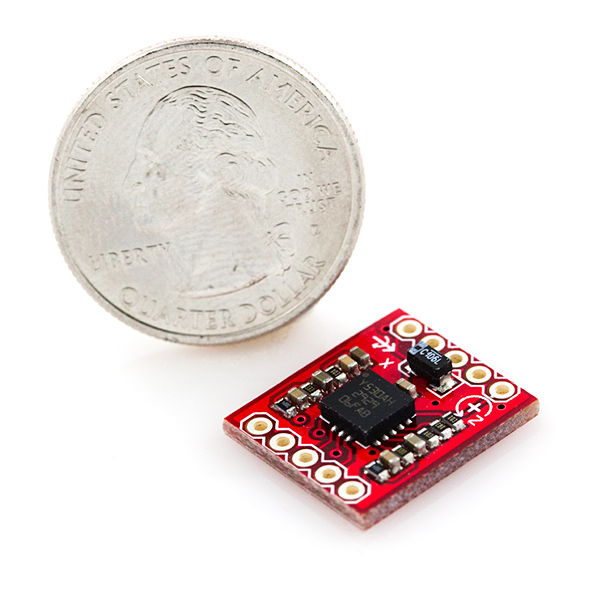
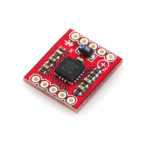
This is a breakout board for the ST's dual-axis LPY503AL gyro. The LPY503AL measures angular velocity along the pitch and yaw axes with a full scale of ±30°/s. Two different analog outputs are provided for both the x- and z- axes - one 1x amplified and the other 4x amplified.
A regulated voltage between 2.7 and 3.6VDC should be supplied to the power pins. We have the filtering circuits all set up; you'll just need to connect the outputs to an ADC, and you're ready to go.
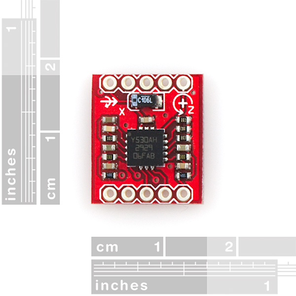
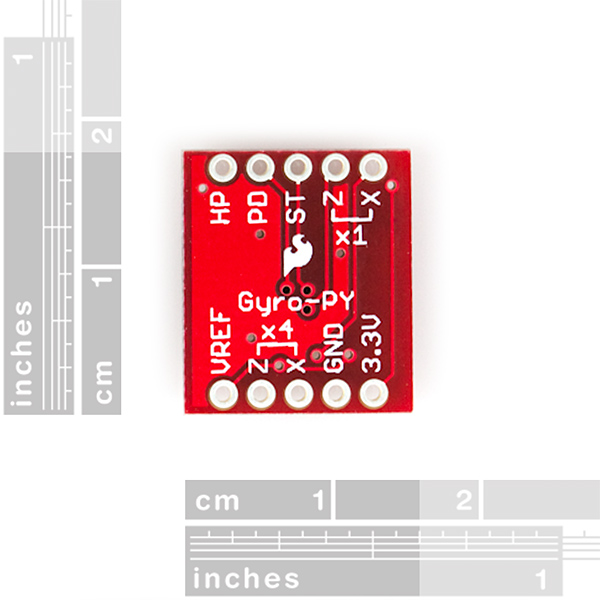
This breakout board includes the gyro and all necessary filtering capacitors as shown. The 1x and 4x amplified outputs of both axes are connected to the 0.1" pitch headers, along with the power-down, self-test, high-pass filter reset, and power pins.
Not sure which gyro is right for you? Our Accelerometer and Gyro Buying Guide might help!
- 2.7 to 3.6VDC power supply
- Dual axis, pitch and yaw sensing
- 1x and 4x amplified outputs for each axis
- Low power consumption
- All necessary filtering components included
- Access to power-down, self-test, and high-pass filter reset pins
- 0.6x0.7"
Comments
Looking for answers to technical questions?
We welcome your comments and suggestions below. However, if you are looking for solutions to technical questions please see our Technical Assistance page.
Customer Reviews
No reviews yet.
BenF: ? or more likely the gyro chip itself
I looked further into this and found that the issue is not with the gyro chip, but rather the SparkFun board design. The HP filter transforms the output characteristic from that of a gyro to that of an accelerometer.
I managed to modify the board and bypass the HP filter - and without the filter it works pretty well (as a gyro that is). Output now drops back to vref immediately when rotation stops (with the filter it will output a sharp reverse rotation and then slowly settle).
Feedback on whether this design is intentional (you want the accelerometer behavior) or not would be appreciated. If so - you may want to put it in the accelerometer category and change the product description accordingly. If not - I would welcome a modified design based on the same chip, but without the HP filter.
Benf,
I am totally agree with you. I sent an email explaining the situation. Sparkfun technicians told me they are starting to modifying these boards. They also told me a instantly solution would be removing the capacitor and short resistance but I dont want to take the risk.
Could you please share specifically what modifications you made? I need to use this device for a project very soon. Though I think I may be able to work out what needs to be done.
I had the same problem as BenF - I desoldered the Z axis filter components and shorted pins 9 and 10, which is the recommended configuration (per datasheet) when omitting the HP/LP filters; this got rid of the long negative overshoot. The 4X output settles at Vref + 0.03V when at rest now, though, whereas before it would eventually settle right on Vref.
Thanks guys. I bought this board couple of years ago and had given up on it due the the problems described. Your fix worked perfectly. Due to it being my first attempt at soldering SMDs I think I stuffed the Y axis, but the X is now working as it should and thats all I need.
I did a little investigating of my own using my DSO Nano ( http://www.sparkfun.com/products/9625 ) and found the tale tail signs of an RC time constant, clearly a result of the (optional, but included) high pass filter suggested by the data sheet. To counter this, I simply took a small strand of copper (from a stranded wire) and soldered it on top of the capacitor. (for the Z axis this is the second white device up on the right side, or fourth device including the resistors). Comparing the Z and X axis' readings I can clearly see the X still has a significant 'ring' (just an up and down oscillation that fades quickly) when dropping one edge of the board about a half an inch. Doing the same on the modified Z axis results in a very clear corner.<br />
<br />
As for the long fade I currently don't have the instrumentation to measure it, but I will be able to post more info later this week when I have access to a LabView DAQ.
I have one issue with this board (or more likely the gyro chip itself). Sensitivity is as advertized however when you stop moving - it creeps in the reverse direction for a long time. Ideally output should immediately settle at vref whenever it stops moving around the axis.
Due to this issue a calculated integral for absolute position can not be relied on.
I've previously used the LISY300AL board and thought I could do better with this 10 times more sensitive gyro, but not so. I actually get far better results in the +/- 30 deg range with the less sensitive board.
The above issue has been observed with differential and absolute ADC sampling for both 1x and 4x outputs.
When it says, "A regulated voltage between 2.7 and 3.6VDC should be supplied to the power pins." does pinS refer to 3.3V AND Vref?
Yes
I was installing this Gyro today in a breadboard and realized that the axes and pinnouts are on different sides. On the next revision it would be nice to have them both on the same side so you don't have to keep flipping the board back and forth. Not a big deal, just an idea that I think would be beneficial