- Home
- Product Categories
- DC/Gearmotor Driver
- SparkFun Motor Driver - Dual TB6612FNG (1A)


SparkFun Motor Driver - Dual TB6612FNG (1A)
The TB6612FNG motor driver can control up to two DC motors at a constant current of 1.2A (3.2A peak). Two input signals (IN1 and IN2) can be used to control the motor in one of four function modes - CW, CCW, short-brake, and stop. The two motor outputs (A and B) can be separately controlled, the speed of each motor is controlled via a PWM input signal with a frequency up to 100kHz. The STBY pin should be pulled high to take the motor out of standby mode.
Logic supply voltage (VCC) can be in the range of 2.7-5.5VDC, while the motor supply (VM) is limited to a maximum voltage of 15VDC. The output current is rated up to 1.2A per channel (or up to 3.2A for a short, single pulse).
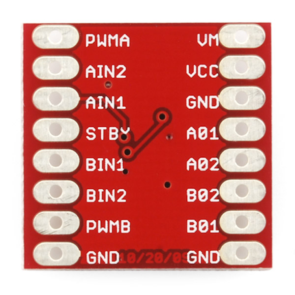
Board comes with all components installed as shown. Decoupling capacitors are included on both supply lines. All pins of the TB6612FNG are broken out to two 0.1" pitch headers; the pins are arranged such that input pins are on one side and output pins are on the other.
Note: If you are looking for the SparkFun Motor Driver with headers, it can be found here or in the Recommended Products below.
- Power supply voltage: VM=15V max, VCC=2.7-5.5V
- Output current: Iout=1.2A(average) / 3.2A (peak)
- Standby control to save power
- CW/CCW/short brake/stop motor control modes
- Built-in thermal shutdown circuit and low voltage detecting circuit
- All pins of the TB6612FNG broken out to 0.1" spaced pins
- Filtering capacitors on both supply lines
- 0.8x0.8"
- Schematic
- Eagle Files
- Hookup Guide
- Datasheet (TB6612FNG)
- bildr Tutorial
- GitHub (v1.1b)
SparkFun Motor Driver - Dual TB6612FNG (1A) Product Help and Resources
Light-Seeking Robot
November 28, 2017
We use parts from the SparkFun Inventor's Kit v4.0 to create a light-seeking robot that mimics the behavior of single-celled organisms.
ReconBot with the Tessel 2
October 13, 2016
Build a robot with the Tessel 2 that you can control from a browser on your phone or laptop.
Experiment Guide for the Johnny-Five Inventor's Kit
June 28, 2016
Use the Tessel 2 and the Johnny Five Inventors kit to explore the world of JavaScript enabled hardware through 14 awesome experiments!
TB6612FNG Hookup Guide
September 29, 2016
Basic hookup guide for the TB6612FNG H-bridge motor driver to get your robot to start moving!
Core Skill: Soldering
This skill defines how difficult the soldering is on a particular product. It might be a couple simple solder joints, or require special reflow tools.
Skill Level: Noob - Some basic soldering is required, but it is limited to a just a few pins, basic through-hole soldering, and couple (if any) polarized components. A basic soldering iron is all you should need.
See all skill levels
Core Skill: Robotics
This skill concerns mechanical and robotics knowledge. You may need to know how mechanical parts interact, how motors work, or how to use motor drivers and controllers.
Skill Level: Rookie - You will be required to know some basics about motors, basic motor drivers and how simple robotic motion can be accomplished.
See all skill levels
Core Skill: Programming
If a board needs code or communicates somehow, you're going to need to know how to program or interface with it. The programming skill is all about communication and code.
Skill Level: Rookie - You will need a better fundamental understand of what code is, and how it works. You will be using beginner-level software and development tools like Arduino. You will be dealing directly with code, but numerous examples and libraries are available. Sensors or shields will communicate with serial or TTL.
See all skill levels
Core Skill: Electrical Prototyping
If it requires power, you need to know how much, what all the pins do, and how to hook it up. You may need to reference datasheets, schematics, and know the ins and outs of electronics.
Skill Level: Rookie - You may be required to know a bit more about the component, such as orientation, or how to hook it up, in addition to power requirements. You will need to understand polarized components.
See all skill levels
Comments
Looking for answers to technical questions?
We welcome your comments and suggestions below. However, if you are looking for solutions to technical questions please see our Technical Assistance page.
Customer Reviews
4.7 out of 5
Based on 18 ratings:
1 of 1 found this helpful:
Great chip to pair with the LIght Blue Bean
Since all of our students have iPads, we use the Light Blue Bean Arduino compatible microcontroller in our Physical computing class. This means that we need a motor driver that operates at a 3v logical voltage to get a signal from the bean.
This chip seemed to be the best fit for us.
I do wish there was a way to get the chip in a style that could be easily put into a breadboard without having to solder headers on.
Seems like the price could be a little lower.
Also, the standby pin is not necessary for our needs, but in order for the chip to work, you have to wire Standby to 3v, adding a little bit of complexity for novice students.
Ideally, what I would like is a version of the L293D chip that will operate at 3v logic, but this will meet our needs for now.
2 of 2 found this helpful:
DC Brushed Motor Life Test.
I used the TB6612FNG motor driver as part of a 24 motor life test stand. The motors are switching direction every 100ms causing a current spike of > 2 amps. The test has been running continuously for a week with out any issues. Each of the TB6612FNG motor drivers worked right out of the box saving me a lot of time.
5 of 5 found this helpful:
Gets the job done just right!
I've owned two of these motor drivers. I've used them to drive a self-balancing robot and the rover 5 chassis. I've never ran into any problems with it. For the rover 5, I keep each treads' two motors in sync by simply hooking them up together from one motor output. Perhaps this limits the bot's speed, but it's good enough for me.
I've controlled the driver with an assortment of microcontrollers: Arduino Uno, Arduino Mega 2560, bare atmega328, bare attiny84. I've also powered the driver with rechargable AAs, regular AAs, and a 7.4V Li-Poly battery (sold here @ sparkfun). All of which work as expected.
Works well
Works just as expected.
This was just what I needed
I was doing a little DYI RC car and I needed something to control the motors with. The motors were salvaged from something else and way underpowered but the driver did exactly what it was advertised to do. I'll be getting some better motors and trying again soon. The only thing that was a little tricky was soldering the headers on since it was so small, but that's more my inexperience than anything.
Nice package and features
so nice to not have to worry about flyback diodes, smart control bits are great, worked like a charm and these are things that fall in the category of "should have one in my bin all the time"
Very easy to use
This is a very easy to use motor driver. Using the bildr.org tutorial linked from the product page, it took me only minutes to get two motors running off of it using Python on a Raspberry Pi 2.
Super easy to use
The built-in 200K resistors make this just plain fun to use. No need to worry about hooking it up directly to your micro controller pins. However, I did notice one thing that seemed weird to me.
I used the same power source for both the motor and the logic side and I used a function generator to supply the PWM. When I switched off the power supply the motor kept turning very slowly and I realized that the PWM supply was running it. I checked it out and when the power supply was on the current running through the PWM line was 0.02mA. When I switched off the power supply the current jumped to 9.0mA.
Worked great driving toy robot
I'm using this and an Arduino Pro Mini to control the drive motors of a Hexbug "Battle Spider". Using the linked bildr tutorial it was easy to get everything wired up.
One problem with the bildr tutorial though: their provided move and stop functions don't reset the PWM outputs. I was running a motor test to discover which direction the motors ran. After running motor A both ways and stopping I couldn't run motor B without A running as well.
All that is needed is to analogWrite 0 to both PWM pins in the stop function.
Solid device
This guy does exactly as advertised, with a tiny form factor. It gives me great control over my robot, and fits inside the chassis to protect itself from harm. Thanks, Sparkfun!
Great foot print
They designed this super great. The layout of the pins works wonderfully, as compared to a cheap Chinese board that I got off the Internets somewhere a while back. So much easier to wire up and makes the wiring shorter and all around better for my lockitron setup! For short, love it!
Works great
Just as I expect from SparkFun, this handy little breakout works great and is easy to use.
Works fine
This is a fine breakout and works as advertised. I am trying to drive two motors which drive the treads of a toy tank. These motors draw 1.2 amps at full stall, or maybe even slightly more, so they are right at the edge of what this driver can support. I became interested in this chip because I have a Pololu Qik that I tested with my tank and it did really well. The Qik has an identical TB6612 chip but also incorporates a serial chip and some other features. So I bought this breakout and also a breakout from Adafruit. Neither this breakout or the Adafruit one performed very well with my high-draw motors.
Anyway, not really a complaint, as I am really pushing the limits of this chip, but it really makes me wonder what makes the Pololu version function so much better. Trace layout, IC footprint, thermal relief? I would be delighted if an EE weighed-in on the differences.
I wrote up some of my findings on my blog: https://manisarobot.blogspot.com/2018/01/more-about-motor-controllers.html
I'm using this board with IOIO board controlling a magician chassis. Aren't I supposed to be able to have one wheel turn CW and the other CCW at the same time? When I've attempted it I get no wheel motion.
I noticed that the design for this part
SparkFun Motor Driver - Dual TB6612FNG (1A)
Was not on github. Any chance you could put it up?
Thanks.
Sorry about that! It is up there now here.
A very nice flyback diode configuration for this motor driver: http://www.instructables.com/id/Using-the-Sparkfun-Motor-Driver-1A-Dual-TB6612FNG-/
and here is a demo of my use of the circuit: http://vimeo.com/61068377
The datasheet listed among the documents up above contains some Asiatic symbols, or some cryptic codes to replace them in absence of fonts. English-readers will have a hard time understanding some of the tables and charts. As an alternative, read this one:
http://www.semicon.toshiba.co.jp/docs/datasheet/en/LinearIC/TB6612FNG_en_datasheet_080509.pdf
Be aware I just fried this board and my MCU (a Teensy++) by turning on the motor voltage VM (12v) first before turning on the 5v Vcc. It had been working great for weeks before that. I'm not sure why this would cause it to burn out as the VM seems to be isolated from the Vcc, and STBY would be low if there was no Vcc, so everything should be disabled. But anyway be safe and connect Vcc before the motor supply VM.
Yeah I believe I just did the same thing.... oops. Guess I'll order another.
If you are playing with that chip, be sure you plug the standby pin (STBY) to 5V to enable the motor driver and make it work. It has a internal pull-down 200k resistor, by default the motor driver is disable.
This could really use a "not" gate on one of each of the "InA" and "inB" lines. Like a Not-AIn1 and Not-Bin1, so that people not interested in the braking function can use the controller by running one logic line to both In1 and In2. I suspect that there are a lot of people with low-pin count uC's who would appreciate not having to use 2 more GPIO's and not having to add extra logic.
Otherwise, this is one of the best "hobby motor controllers" I've found at this price. (in case anyone is interested) It gets kinda hot running Tamiya gearboxes, but it works!
Can I use this to control 4 motors without overloading the chip? i.e. two of the left side wheels work in unison and the two of the right side wheels work in unison, but both the left and the right set of wheels are independent of each other.
hi there,
i don't know if anyone else notice that and put a comment below i took this driver and i didn't notice that before VM1 & VM2 and motor GND1 & GND2 of both connected together not allowing to drive different VM motors and more important impossible to put current sensing on each motor how it can be possible a mistake like that ?? if an IC has different pins why do not allow the user to join them together if needed ?!?!?
it's not the first time i notice this kind of mistakes on sparkfun production ...
so in my case i have to cut wiring on the board OR buy a new one .....
anyone has thoughts about it ?
rik
I used these to drive two Roomba motors in my Talking Autonomous Robot. They work great and don't even seem to get warm with extended use. Takes up to 15 volts which works out well with the Roomba wheels.
If someone need it, I wrote a library for this driver. It does exactly the same as the function from Sparkfun, but is (hopefully ;-)) a bit easier to use: http://wikisend.com/download/121974/motor_library.zip
I have a Tamiya duel gear box and the motors are ratted for 3V max and this driver wants at least 4.5V for VM. should I use more voltage on the motors or use 3V on the driver?
The datasheet says that there should be another 10uf Cap on the VCC of the TB6612FNG. Is there a reason you guys omitted this one?
Uh, so I just received mine a few days ago. I have a baffling, problem here. I was puttering around and forgot to connect Vcc, but did connect my 8V motor voltage, set standby to high, and applied my PWM signal. It turned on without Vcc and it seems to work normally (I think)!!
Vcc voltage seems to be about 1 volt less that whatever voltage is input to the PWM input voltage. It does not seem to change with motor voltage I can even power an LED off the Vcc pin, but some of the input waveform makes it through.
Anyone know if that is "normal"?? I don't know if something is damaged inside the IC, or if it is behaving normally. It seems rather odd that Vcc does not need to be connected and can output a current.
Update: Controllerface (4 years ago) and c-scott (2 years ago) addressed this (see way below), It seems like I should at least put a diode in-line with Vcc and power Vcc first. I still don't really understand why, or if I can just forget about powering Vcc. c-scott mentioned the possibility of an internal diode at Vcc and I did notice the driver heated up a lot if I actually connected Vcc to my circuit (AFTER connecting VM). Still confused....
As I wrote, there's an internal protection diode which is powering Vcc for you, at a voltage drop of about 0.6V (which is what you are measuring). Although this works and won't damage the chip in the short term, it's not an idea long term because the internal protection diode isn't really meant for high currents.
Just connect Vcc to your microprocessor's power supply. "Heating up a lot" is what the driver is supposed to do when running a motor. If it wasn't heating up before, it probably wasn't actually turning the motor fully on.
Can anyone confirm that applying Vm before Vcc actually fries this thing?
No, it doesn't "fry this thing" -- at least not immediately. Vcc will be powered through an internal protection diode. It's still not a good idea to leave it in this condition indefinitely.
The datasheet states IN1 L, IN2 L, PWM H is high-z/stop. Does anyone know what IN1 L, IN2 L, PWM L does? The datasheet doesn't list it as far as I can tell.
Will this work with a brushless DC motor?
I don't believe so - to run a BLDC motor, you need three half-bridges. This technically has four of them, but looking at the truth table I don't think you have enough independent control of them to do what you need (hint: it's missing the H-H state). You should be able to do it (control one motor) with two of these chips.
We're looking into producing a BLDC motor driver board, but we haven't chosen a chip yet. Out of curiosity, what voltage and current does your motor require?
I was looking for around a 3S LiPo (11.1V) pulling up to about 3A... Of course higher voltage and current handling than that could be useful as well! :)
Feature request. How about adding a resistor pad with cut out short between the PGND pins and the ground bus. With a trace off the PGND pin to the control header or just a hole would do. So we can monitor the motor current with an ADC pin without hacking up the board.
I didn't really think about it when I ordered, but this tiny board has no allowance for a mounting hole. Worked electrically just as I expected to control a couple motors, but I haven't decided how to mount it yet. Any suggestions?
Velcro, hot glue, or twist ties (keep an eye out for possible shorts with these) all work well.
Here's a good tutorial: http://www.meanpc.com/2012/01/how-to-use-tb6612fng-motor-driver-with.html
Hi. Is it possible to have two motors with different voltages with this board? For example 5v and 12v.
thank you
holby
Unfortunately not; although the chip has two separate H-bridges, their motor supply voltages are tied together internally on the chip.
For those also looking, here's an open source project using this part AND a it contains a part definition for Fritzing. Whoopie! https://github.com/ducas/Robbo
The PCB view definition is broken though.
A working part definition is now available here: http://code.google.com/p/fritzing/issues/detail?id=875
Is there a Fritzing part definition for this out there somewhere?
Is there any problem tying STBY to VCC? I've failed to find a conclusive answer. It looks like as long as I have all lows,I still "coast" and so it should be ok to tie STBY to VCC. But, I don't want to be wrong :p
I did a quick video tutorial/review which discussed how to use and connect with an Arduino - http://youtu.be/BiJMsMguv-M?hd=1&t=8m9s
great driver
I'm moving a project over to this driver from one where all control was through 4 PWM pins (2 per motor). To drive CW, for example, you would hold A high and pulse B low, and to drive CCW, you would hold B high and pulse A low. This board is set up instead to take 2 slow inputs and 1 PWM input per motor, with the slow inputs setting the direction of rotation (in the exact same manner as my existing project, one side high and the other side low = drive) and the PWM input setting the speed. My question is, will the "slow" directional inputs tolerate being switched at PWM speeds? Can I just tie the PWM inputs high permanently and use PWM on the directional inputs instead?
*edit: Upon closer inspection, my other board uses this exact same chip, and that is in fact what they did. So yes, that will apparently work. I'll update if I smoke it. ;)
Board seems to work. one side is disabled. i used the diagram in the bldr.org to test. what am i missing?
Hello folks,
I've been playing with a stepper motor and the easydriver shield for only one reason so far: I'm able to stop the motor and keep it energized. (I mean, not moving but it still has the torque to keep tied something)
I'm thinking of start playing with Dc Motors and this Motor Driver TB6612FNG. My question is: Is it possible to stop the motor and at the same time keep it energized? (not moving at all)
Thanks
**** Maybe I need a worm gearbox motor, right?
Dc motors spin when power is applied, so no you cant power it and have it not move onless you lock it up mechanically. Motors dont like this and it eats power. There is a braking function on these though, it effectively shorts both motor terminals to ground.
For those that asked how to add back-EMF protection diodes around the motor, see figure 6 of http://www.sparkfun.com/datasheets/Components/General/L298N.pdf
how come my motor is slower when it is control by this than just connecting it directly to a battery
i answered this above
can you teach me how to properly wire this to control two dc motors
does this thing work like an h-bridge
yes
I bought two of these and they are great little boards. I am controlling the motors from a pc app. that I made via serial port. Thanks Spark Fun.
With this board and an Arduino I can finish the robot project I started 30 years ago.
I have had a surplus big trak gear motor set in a box for all those years. Back then I was going to use a Timex Sinclair t1000 with a IO board to control it.
Here is the guts of the big trak
http://www.thebigtrak.com/legacysites/robotprojects/
Its a great gearbox. It has a magnetic clutch that keeps the two sides running at the same speed when going the same direction, but if you apply reverse or hit some threshold, it "breaks" and the two sides run independently.
I'm having some trouble figuring out exactly where I should place the backflow diodes if I were to use this with two motors.
Any help?
Would it be possible to use this controller with a 3.3v operating voltage like on the arduino pro mini ?
Would it be possible to use this controller with a 3.3v operating voltage like on the arduino pro mini ?
Yes. Vcc can go down to 2.7v. You'll need a higher voltage to run the motors, though (connected to VM), which is usually also a good idea since it keeps noise isolated. For example, running off a standard 7.2V battery pack, you'd connect the battery pack directly to VM and GND here, and then connect it also to the voltage regulator input on your arduino. The arduino's 3.3V output would then be connected to VCC on this board.
Great motor driver. Used in a line following bot. Always ran cool (though we weren't stressing it, maybe 30% average of max current). Ran high-power versions micrometal motors.
It's cheap and it works well. Not much to be said; it's a good product!
hey guys i can't get this to work maybe you can help me. Im using a teensy 2.0 powered with usb bbut I'm sorta familiar with the arduino software. I know the teensy is working because I programmed the led to blink and i tested my motors(pololu 1:50). I have the standby pulled up to 5v and my motor connected to Ao1 and Ao2 and a pwm line from pin 9 on my teensy connected to PWMa. I grounded the 2 ground pins at the bottom and connected power from the usb to vcc(i also tried AA batteries). Ive played around with AIN1 and AIN2 but I'm not getting any response at all. Does anyone know why this wouldn't work? thanks so much for any help i love spark fun.
You'll need to apply power to VM as well as VCC.
Also, USB ports don't generally provide much power; it may not be a good idea to drive the motors directly from USB voltage. Try connecting a nine volt battery between VM and ground, thereby powering your motor from the 9V battery. That might work much better.
If you haven't used protection diodes on your motor, it's also possible that you've toasted the board. You can disconnect the motor and look at the voltages on the output directly (using a voltmeter) to verify that the board is still doing the right thing.
I am using this motor driver and I noticed that my motor is noticeably slower than when it is hooked directly up to the battery.
I have a 12v 1.2Ah battery. I have it fed into an 7850 5v voltage regulator. I used the voltage provided from the regulator to put a full duty cycle to the PWMA pin, and feed the input pins.
I have another wire from my 12v battery going into the VM pin on the board. The motor stops, moves both ways, etcs, just slower than if I put it directly on the battery. A much more significant drop in speed than I think it should be.
Any ideas why?
Check that your PWM signal is really 100%. Many PWM signals can't actually get all the way to 100%. Move the PWM input on the driver to a digital output pin on your microcontroller and just drive it high directly -- if that runs faster, then you've found the cause.
This motor driver works great for the Magician Robot Chassis. I've created PWM code using the MSP430. The code can be found at MSP430 TB6612FNG Driver Code
Thank you VERY much!
I want to control the speed of a 5v DC (0,15A, 50mm x 15mm) computer brushless fan that will be powered by a battery pack (4x AA rechargeables= 4,8v) or with a USB outlet. Would this driver be able to do this? Is there a dimmer switch out there that I could plug between the batteries and the fan? (I'm a newbie in electronic; I'm looking for something really simple.
Thanks
did you make this work?
Does anyone know if the chip's internal output diodes are for kickback protection or only there for ESD protection?
I see that the typical application diagram shows no external diodes, but I'm curious if anyone has experienced problems with this, or the similar Pololu breakout.
The datasheet provides a back-emf warning at the end. I would assume the internal diodes are only there for ESD protection, they are probably not fast enough for back-EMF suppression, although the chip will probably not self-destruct immediately if you skip the external diodes.
Did anybody tried to use the TB6612FNG with the Arduino Uno or Mega to control stepper motor? Preferably using three drivers and three motors? Thanks
This motor driver is amazing. It is so small and so reliable. I use it to drive my iphone controlled search and rescue robot. It drives 4 micro 100/1 motors and tracks.The size of the board makes even better. The only con is that it does not have protection against back EMF. Overall very pleased.
From looking at the data sheet the internal schematic on page 3 shows 4 diodes on the output pin to protect from back EMF in the standard H driver setup.
Those internal protection diodes are probably not fast enough to catch back EMF. There are there for lockup protection. You should probably add your own back EMF protection diodes, fast ones.
thanks that helps
I don't get it. Does this thing output PWM (based on the input), or does it ramp up current/voltage based on the PWM input? If I only want my motors to go Forward (ie: I'll only ever be using one of the four "modes"), do I need this thing?
Also, does this chip protect against back EMF, or should I add diodes to the circuit just in case?
Does it ramp or does is PWM?:<br />
It outputs a PWM. You are relying on your motor to be the low pass filter. Almost all DACs work like this at some level. <br />
<br />
Do I need this?<br />
Nope! but you can do 4 motors with this in 1 direction each!, so thats pretty cool. All YOU need is one Mosfet. Tie one terminal to gnd and the other to the FET, and just switch that. <br />
<br />
Are we protected against back EMF?<br />
Nope... if you are using something like LiPo/LiIon battery I would definitely be worried about this. If you are using a sealed lead acid or alkaline, don't worry about it unless you have super inductive loads, all you will do is recharge the battery. You will have to use your own judgement for NiCAD, NiMH etc.
Kickback will degrade the chip, and wouldn't "recharging" an alkaline battery be bad? Heh, somehow I'm clueless with motor drivers at the same time...
I've been using this board for a little while in a project, and i've noticed that it seems to function just fine without any power applied to the logic (VCC) pin. So far, I haven't noticed any issues, but i'm curious if anyone has any thoughts on whether or not this is a good/bad idea? Motor operation seems to be unaffected with it powered or not. Also, spec sheet says that the TB6612FNG has a VM in minimum of 4.5 V, currently i'm supplying it with 2 AAA batteries (right now, at 2.6 V) and nothing on the VCC line, am I going to fry this thing?
There's usually a protection diode on VCC. I'm guessing you're inadvertently powering the chip through its internal protection diode. I wouldn't recommend that: the protection diode isn't rated for high current, so you will probably eventually end up toasting that internal diode.
Why not just connect VM and VCC?
As a previous poster mentioned, exceeding the low range of VM will cause your rise times to be slower, but that shouldn't cause any harm, as long as your PWM rate is also relatively low.
I got some of these for a project I was working on, and they are very easy to use. Each one can drive 2 separate motors that pull up to 1A each, or you can wire them both in parallel (send the same PWM to both A & B) and hook up both outputs to one motor to get up to 2A. I used an Arduino to control them, but any microcontroller with PWM outputs will work.
Fantastic + Cheap = Awesome
No i mean can i use it for Vm to power the motors?
Bit of a late reply, but yes, the H bridge will switch anything down to 4.5 V (and up to 15V) as a motor supply. You can likely go quite a bit lower, but you may not get reliable switching. For instance, if you were to use a 3V supply you may get a slow rise time. <br />
<br />
Just be sure you use the 6V for the VM only and not the VCC or signal levels.
Can I use a 6.0V -1.7 Ah battery with this?
as long as it gets regulated to 5.5V you should be ok
I am fairly new to electronics and am wondering if you can wire a Micro Metal 30:1 Gearmotor directly to this driver or is there extra circuitry required to provide the correct amount of current? What is a recommended means for a power supply with that motor and this driver, and is their additional circuitry their or would that connect directly to Vm?
Hi Jwalker, The motor driver can actually supply power to 2 of those motors. It allows you to pass more current and voltage to the motors than a micro controller can handle. If you were to pass the same amount of power required to run a motor with though say an Arduino, you would fry the Arduino.
I used this motor driver with the mini sumo bot "Scrapper" that we entered in Robothon '09. For the bot I used 2 lipos run in Series to supply 7.4V. This allowed enough power to run the motors well, and also was a low enough supply voltage to be regulated down by the Arduino on board. This let me use one power supply for the system.
If you are just getting started with electronics, the Arduino is a great starter micro controller unit, and would be a very good unit to use to control this motor driver, unless you already have a different micro controller in mind.
This might help you out a bit once you start working with the module.
http://www.arduino.cc/cgi-bin/yabb2/YaBB.pl?num=1263858213
Thanks for the link to your code! That makes this MUCH clearer. I also had trouble reading Toshiba's PDF...Did you have to use any diodes for back-EMF protection (if so, where)? I hope to use this with 2 small (6V, 100-400 mA).
Thanks for the advice. I have already purchased the Arduino main board. I am just concerned with EMF and causing damage without use of a protection diode (I just dont know how to wire that with this driver to still allow a motor to be bidirectional)
Had someone else try as well, something seems corrupted with the file.
OK, another person checked with Adobe Reader and it was OK, apparently it uses asian fonts and that is messing things up
Thanks for bringing this to our attention. We will look for a new datasheet for this module. I had to download an Asian font set as well. It corrected some of the issues, but there still seems to be some errors. If we can find a better document, we will post it shortly. Also for anyone experiencing issues with this document, be sure to have your Adobe Update download the needed fonts. It will help allot.
Anyone else have problems with the attached datasheet? Some of the entries in the table are just garbled text. Tested with Sumatra PDF and Foxit.
If you are looking for that part in the Sparkfun eagle library they named it "TB6621FNG" instead of "TB6612FNG"
mix the 21 instead of 12
you can also make a search of "toshiba" and check the description box and look for sparkfun.
have fun!
Is there any reason why I couldn't wire both channels to a motor in parallel to get ~2A on one motor?
I played around with this today and got it to work fine. I also hooked up a BlueSMiRF to remote control it. Here is some code I shared:
http://www.arduino.cc/cgi-bin/yabb2/YaBB.pl?num=1263858213
Hope you enjoy.
it says that the input signals need to be PWM. Dose this mean that i can just hook up my RC reciever to it?
PWM stand for pulse width modulation. You'll need a microcontroller to send pulses to the chip. I just got the board, so I havn't figured out how to control the speed but sending a high signal to AIN1 and a low to AIN2 controls the direction.
Having lots of success with this driver, the dual motor gearbox from Tamiya, and the Duemilanove. Very easy to control with analogWrite().
Could someone explain how to use the input signals to set the motor in one of four function modes (CW, CCW, short-brake, and stop) ?
Never mind, the datasheet explains it. I will test this when I get it.