- Home
- Product Categories
- WIZnet
- WIZnet W5100 Network Module with Mag Jack - WIZ811MJ

WIZnet W5100 Network Module with Mag Jack - WIZ811MJ
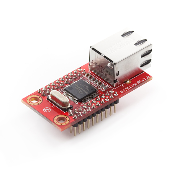
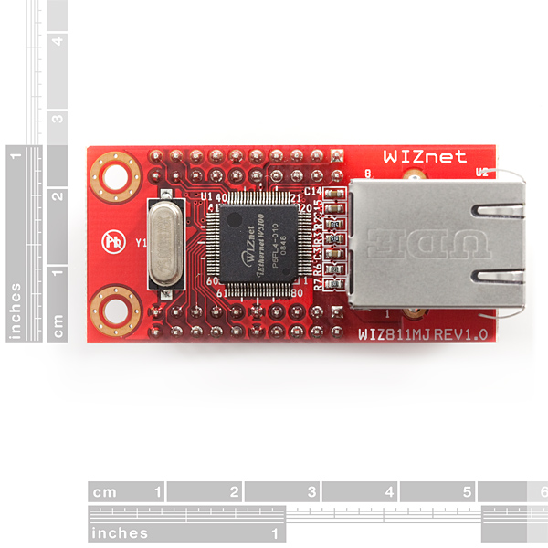
WIZnet's WIZ811MJ works as a breakout board for their W5100 embedded TCP/IP chip. Also included on the board is an RJ-45 MagJack connector (RJ45 with X’FMR). It can be used as a component and little effort is required to interface to the W5100. The WIZ811MJ is an ideal option for users who want a simple solution to adding TCP/IP capability to their project.
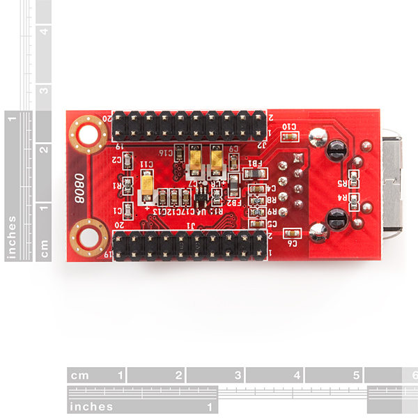
There is no on-board regulation, so you'll need to supply clean/regulated power sources. All pins of the W5100 are broken out to two pairs of 10-pin, 0.1" pitch headers.
For detailed information on implementation of Hardware TCP/IP, refer to the W5100 Datasheet.
- Supports 10/100 Base TX
- Supports half/full duplex operation
- Supports auto-negotiation and auto cross-over detection
- IEEE 802.3/802.3u Compliance
- Operates 3.3V with 5V I/O signal tolerance
- Supports network status indicator LEDs
- Includes Hardware Internet protocols: TCP, IP Ver.4, UDP, ICMP, ARP, PPPoE, IGMP
- Includes Hardware Ethernet protocols: DLC, MAC
- Supports 4 independent connections simultaneously
- Supports MCU bus Interface and SPI Interface
- Supports Direct/Indirect mode bus access
- Supports Socket API for easy application programming
- Interfaces with two 2.54mm pitch 2 x 10 header pin
- Temperature : 0 ~ 70°C (Operation), -40 ~ 85°C (Storage)* Board: 55.5x25x23.5 (W x H x D)
- Datasheet
- Schematic
- W5100 Datasheet
- WIZnet Product Page (more documents and downloads)
WIZnet W5100 Network Module with Mag Jack - WIZ811MJ Product Help and Resources
Core Skill: Programming
If a board needs code or communicates somehow, you're going to need to know how to program or interface with it. The programming skill is all about communication and code.
Skill Level: Competent - The toolchain for programming is a bit more complex and will examples may not be explicitly provided for you. You will be required to have a fundamental knowledge of programming and be required to provide your own code. You may need to modify existing libraries or code to work with your specific hardware. Sensor and hardware interfaces will be SPI or I2C.
See all skill levels
Core Skill: Electrical Prototyping
If it requires power, you need to know how much, what all the pins do, and how to hook it up. You may need to reference datasheets, schematics, and know the ins and outs of electronics.
Skill Level: Noob - You don't need to reference a datasheet, but you will need to know basic power requirements.
See all skill levels
Comments
Looking for answers to technical questions?
We welcome your comments and suggestions below. However, if you are looking for solutions to technical questions please see our Technical Assistance page.
Customer Reviews
5 out of 5
Based on 1 ratings:
Worked perfectly!!!
The best and easiest way to interface Ethernet into hardware based around the ATMega328P micro-controller!
Hello. I am a newbie here.
I just ordered this module with a 3.3v regulator and a pack of M/F jumpers - does anyone know where I can find a simple schematic of how to wire this up to an Arduino Uno? I see the "Schematic" link attached to this listing, but have no idea how to read it.
So... I have it wired up to my Arduino as follows:
J1-1 to D11,
J1-2 to D13,
J2-1 to 3.3v,
J2-3 to D13,
J2-4 to D10,
J2-9 to Ground.
I loaded up the Ethernet / WebServer example, but nothing is happening.
FYI, I got this working. I had to hookup J2-2 to the Reset pin on the Arduino, so the ethernet module resets when a new sketch is loaded onto the Arduino.
Is it possable to interface this with a Arduino Pro Mini. And if so can someone point me in the direction of howto.
Thanks in Advance
Bought one of these for use with my Fez Panda to add networking at a lower cost than the full shield. It works great but I thought I'd post a few caveats I ran into when working with this just to help people make their decision...
First of all, this really is a full blown alternative to the Arduino shield and works well.
The soldered on headers are actually kind of a pain. You cannot prototype with this on a breadboard as there are two rows of pins on each side and you cannot short them together in the way a breadboard would. This left me with using jumper wires to connect them to my microcontroller. The wires ended up being long and that caused me a couple hours of debugging before I was able to discern that there was no problem with my software, but that the long wires were causing the SPI connection to be faulty.
I was able (for FEZ owners) to use the NETDUINO driver for the W5100 instead of the binary drivers provided by GHI and turn down the SPI speed. This made my setup work, albeit a bit slower than it probably should.
I'm probably going to end up desoldering the headers as they are in my way, I kind of wish this had come with them in the box but not soldered on.
Maybe somebody will have a great solution for me on how they connected theirs.
Have fun!
I also have a FEZ Panda and I decided to purchase an ethernet shield kit to fit the WIZ811 on. I followed the directions of soldering the kit together but when I try to compile any of the examples on TinyClr's site, they fail. There aren't any errors, they just compile then do nothing. They automatically stops debugging. So I wanted to know what drivers from NETDUINO you used. Anything would be helpful.
If requested I could show you the ethernet shield kit I used but it's not from SparkFun.
Thanks.
Just as an fyi, this is the meat of the arduino ethernet shield. With this, a 3.3v regulator, and some female to male jumpers, you have the same thing as the shield at a much lower price. Just make sure to implement some sort of reset for the module as well.
Is there a way to desolder all of the pins on this board? I would like to solder my own wires / pins, but I don't want to do it on top of the existing headers. Thanks!
Sounds like many of us would like to see the pins included, but not soldered, so we had the option. As others observe, it can't be plugged into a conventional "breadboard" anyway, so what exactly is the point? What CAN you plug this into with those pins?
What's the purpose of the tiny holes surrounding the mounting holes?
They appear to be connection "via"s. To connect the copper on the top side to the copper on the bottom side. Not clear why they didn't just make the main mounting holes plated-through like you see on other PCBs.
I just purchased this as a replacement for an official Ethernet Shield on an Arduino Mega. The comments here are a few years old and were specific to a board other than the Mega, so I thought I'd share an update.
Arduino Mega R3: J1-1 to D51 (MOSI) J1-2 to D50 (MISO) J2-1 to 3.3v J2-2 to Reset J2-3 to D52 (SCK) J2-4 to D10 (SS) J2-9 to GND
The important point is that the Serial Slave pin assignment for the Mega is D53, but for some reason the IDE/Software is still using D10 per the Uno.
What's the current consumption for this? Also, do I have to use decouple capacitors? Datasheet says nothing about
Can anybody provide a link to a video or good instructions for a noob on how to connect this either net shield to an Arduino mini pro?
Just got a WIZ811MJ Rev. 1.1 and connected it to my Arduino UNO R3 as in earlier posts, but I get only "server is at 0.0.0.0" and resetting the UNO doesn't change anything. On the WizNet811mj, I get steady green and flashing yellow lights. I've tried adding my gateway and changing the mac address and ip, but no difference. I'm using USB to power the UNO, but added a 12V supply to the power plug, but no difference there either. Here's my connections for reference:
J1-1 (MOSI) to D11, J1-2 (MISO) to D12, J2-1 (3.3) to 3.3v, J2-3 (SCLK) to D13, J2-4 (/SCS) to D10, J2-9 (GND) to Ground, J2-2 (/RESET) to Reset
So, is there a way to check communication between the UNO and the WIZ? Any thoughts on making this work?
I got this working, my leads were too long - shortened them to 7 cm and everything works fine, data is now moving all the way to Cosm.
This product looks great.
Unfortunately, we do not make these in-house, so we don't currently have Eagle files for this board. However, you can find the pinout for this module inside the datasheet linked above. In regards to when they will be back in stock, we don't have a specific date yet, but hopefully soon.
Maybe a stupid question, but how come we don't run the signal through a transformer before the RJ45 connector? as the product manual suggests?
thanks in advance!
In the datasheet you will see the RJ45 connector has a transformer as part of the component.
I connected mine the way "Member #254181" described it above, and no problems except that the current draw required me to put a heat sink on the 5V regulator for the 'Arduino clone' board I was using with a breadboard, as it was feeding a 3.3v regulator that supplied the Wiznet (I built a simple plug-in adaptor board to make this work with the 3.3v regulator and breadboard-friendly pins). It seems that the current draw (according to the Wiznet spec sheet) can be 150ma or so while connected to ethernet. I thought I'd mention that ahead of time. I don't see that as a problem, but it did make the regulator heat up without a heat sink, enough to get my attention when my finger touched it while unplugging DC power from the clone board.
Just wondering, if the LEDs on the light up when the module is powered on without establishing an ethernet connection?
Anyone else having trouble sending data over TCP? Every first transmission of data contains lots (tens of kilobytes) of garbage data before the data I sent myself. Every next transmission seems fine. UDP is also fine.
This sounds like the same problem I was having. Read about my fix here
Also, here are the correct pin mappings for Arduino Uno
J1-1 (MOSI) to D11,
J1-2 (MISO) to D12,
J2-1 (3.3) to 3.3v,
J2-3 (SCLK) to D13,
J2-4 (/SCS) to D10,
J2-9 (GND) to Ground,
J2-2 (/RESET) to Reset
what is the difference between this and http://www.sparkfun.com/products/9472 ? sorry im still new to this
The other chip is faster and doesn't support SPI.
oh ok well im gonna buy a fez domino and will this work the same as a usb wifi card on its usb host?
Looking at the datasheet, it appears that the RJ45 jack on this does have built in connection and activity LED's. Is that correct? The only comment in the datasheet about LED's reads, "Supports network status indicator LED," but that doesn't mean that it has it built in.
Yes, it has connection and activity leds built in the connector. I was surprised with it and how easily I got it working.
If i buy it can i use all the projects for Arduino Ethernet Shield without any change?
I've been using this in place of the Arduino Ethernet shield without any hassles so far, other than lacking cable management.
Refer to the breakout schematic and http://www.arduino.cc/playground/Code/Spi when making connections.
Also note that the module requires a 3.3v supply. If you're building your own 3.3v supply (say for example if you're using this with a Pro Mini), make sure you check the datasheet for the 3.3v regulator you choose, as they usually REQUIRE some external capacitors.
Well, it is the same IC as on the Shield so the lib should work fine. If anyone knows of any issues please speak up.