- Home
- Product Categories
- Arduino Shields
- SparkFun Cellular Shield - SM5100B

SparkFun Cellular Shield - SM5100B
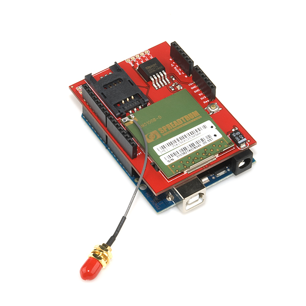
**D****escription: **The Cellular Shield for Arduino includes all the parts needed to interface your Arduino with an SM5100B cellular module. This allows you to easily add SMS, GSM/GPRS, and TCP/IP functionalities to your Arduino-based project. All you need to add cellular functionality to your Arduino project is a SIM card (pre-paid or straight from your phone) and an antenna and you can start sending Serial.print statements to make calls, send texts and serve web pages!
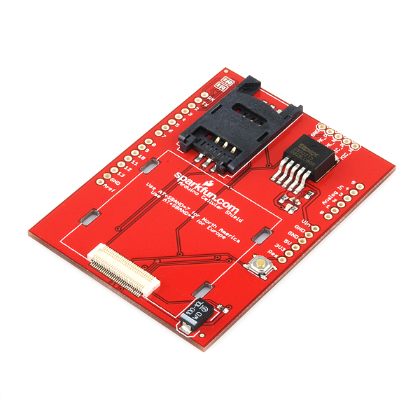
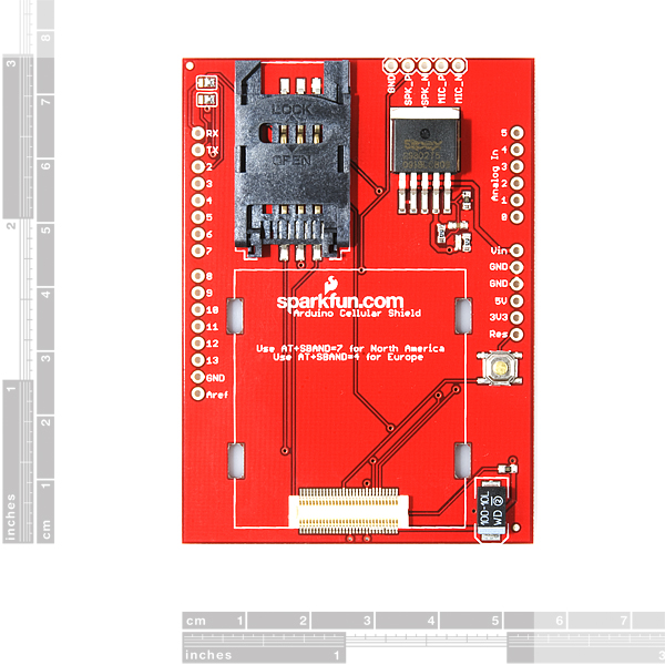
The main components of the Cellular Shield are a 60-pin SM5100B connector, a SIM card socket, and an SPX29302 voltage regulator configured to regulate the Arduino's raw voltage to 3.8V. The board's red LED indicates power. The Arduino's reset button is also brought out on the shield.
Two solder jumpers on the board allow you to select which serial pins interface with the cellular module - software (D2, D3) or hardware (D0, D1). There is also a 5-pin, 0.1" spaced header with connections for microphone inputs and speaker outputs. Headers are not soldered on, we recommend the 6 and 8-pin stackable headers.
The SM5100B cellular module is included with this product, however an antenna is not. It is pre-configured to 9600bps.
- Schematic
- [Eagle Files](http://cdn.sparkfun.com/datasheets/Dev/Arduino/Shields/cellular shield-v12.zip)
- Sample Sketch
- SM5100B Datasheet
- SM5100B Hardware Spec
- SM5100B AT Command Set
- SM5100B SMS App Note
- SM5100B TCP/IP App Note
- GitHub
SparkFun Cellular Shield - SM5100B Product Help and Resources
Core Skill: Soldering
This skill defines how difficult the soldering is on a particular product. It might be a couple simple solder joints, or require special reflow tools.
Skill Level: Noob - Some basic soldering is required, but it is limited to a just a few pins, basic through-hole soldering, and couple (if any) polarized components. A basic soldering iron is all you should need.
See all skill levels
Core Skill: Programming
If a board needs code or communicates somehow, you're going to need to know how to program or interface with it. The programming skill is all about communication and code.
Skill Level: Competent - The toolchain for programming is a bit more complex and will examples may not be explicitly provided for you. You will be required to have a fundamental knowledge of programming and be required to provide your own code. You may need to modify existing libraries or code to work with your specific hardware. Sensor and hardware interfaces will be SPI or I2C.
See all skill levels
Core Skill: Electrical Prototyping
If it requires power, you need to know how much, what all the pins do, and how to hook it up. You may need to reference datasheets, schematics, and know the ins and outs of electronics.
Skill Level: Rookie - You may be required to know a bit more about the component, such as orientation, or how to hook it up, in addition to power requirements. You will need to understand polarized components.
See all skill levels
Comments
Looking for answers to technical questions?
We welcome your comments and suggestions below. However, if you are looking for solutions to technical questions please see our Technical Assistance page.
Customer Reviews
No reviews yet.
UART 5V tolerant?
Driving from Arduino is 5V signalling, however this SM5100B is only operating at 3.8V... unless this module is specifically 5V tolerant on the UART pins(and I can't see this in the data sheet...) then its a time bomb...
Anyone damaged UART on this module?
Interesting question, the datasheet says 3.2v is max.
"then its a time bomb"
I hate it if SparkFun sell such expensive things with errors on them :(
You can find prepaid sim cards for about $10 a month at:
http://www.embeddedworks.net/
http://www.embeddedworks.net/psummary.php?mn=wsim&mid=mwsim4005
Hope that helps
A lot of members on this forum suffers all kind of strange behavior. Mayby I do have a solution. My cellular shield (which was placed on a Netduino Plsus 2) did not to operate reliably. The serial communication refuses completely or stops after a few commands, never reaching the +Sind:4. The SIM card was not recognized or marked as invalid.
It appeared to be caused by randomly and unintended resets during the initialization fase. The reason for this is obvious. The 10K pull-up resistor on the reset-line of the Netduiro is connected to the 3v3 instead of 5V in case of the Arduino. Due to the load of the SM5100b the voltage on the reset line drops to below 2v while according to specification this must be more than 2.2V. (page 20/21 of the datasheet. The sink current is also specified there (2ma.) The Netduiro is keep function but the SM5100B fails a lot of times.
The simple solution is to add a 4k7 resistor between RST and the 3V3. (in parallel to the 10k) A small SMD part fits nice between the two successive pins) Then the voltage rises to approximately 2.7V which is neatly within specification. Hope this help you.
I am not sure of this problem is restricted to Netduiro/SM5100b combinations because even with 5V the Reset pull-up is too weak and still very ctitical.
I don't have the SM5100 but have been messing with the seeedstudio sim900 cell board on an arduino uno. It also is very fussy. On usb from computer power it doesn't have enough power to transmit. when using the lipo rider pro or the energy shield and a 3.7v 3000mAh battery it did seem to work. I ran the energy shield and batt with the sim900 for about two days transmitting every 10min until it failed to transmit due to batt empty. I haven't tried the lipo rider pro through arduino USB though for a long period of time. I guess Im not sure if the header based connection of the energy shield is different than plugging the lipo rider into the usb on the arduino to power. Like does the energy shield supply directly to 5v pin or to the usb? Yea if I was smarter I would do some more testing there. BUT... it does seem that there is a problem with different solutions supplying enough power. And until reading your post I had thought it was just "enough power to the cell modem" but now maybe it is that the power drop is effecting the arduino itself on the reset because the cell modem takes so much juice. It seemed that supplying the arduino dc in with at least 9v supply was more stable for powering all the items attached and getting more consistent results. The problem there is obviously that the convenient solar charging boards cant really be used in that case. I had also thought that maybe 10000uF capacitor across the power supplied to arduino from the lipo rider might stabilize the power dips that may be occurring but so far I have not seem the results I would expect. I also don't have the test equipment to better see what is really happening there.
Ok guys, I've been busy with this shield for 2 days. SOLUTION FOR WEIRD BEHAVIOR:
Use EXTERNAL POWER SUPPLY (uppercase so everyone reads) this saved me a lot of trouble. The usb just doesn't supply enough current. When i did a call it would drop randomly and freeze. Now I use an external power supply at the same time with USB (for sending commands, serial stuff etc.).
try this! It reacts also much faster than without external power supply
Hey 409773. It sounds like you know what you are doing. Would you be interested in helping us on our project for a fee? Where are you located? We are in San Francisco, CA. Thanks. You can respond to me directly: dan@fidosystems.net.
Terrible product. Poor documentation, incompatible with the Arduino out-of-the-box GSM libraries, a big time sink. Wish I had the time to wait for the Arduino store to restock.
After 3 days of non-stop work I am now able to establish a TCP connection in areas where signal is strong, but I am still unable to get data via HTTP GET.
Many thanks to Tobek for posting his approach, which I just found here https://github.com/tobek/SM5100B-GPRS. Looks very similar to mine, except for HTTP GET which apparently works for him. Will give it a shot in next few days.
Hi,
I'm using this module in big project. it is nice, But I face probelm the module is hang in some cases I can't detect this case. So I need a function or an AT command to make restart for module (without arduino). More details about hang the Arduino is receiving that error below in infinite (the GSM module still send it) +CME ERROR: 4
Any suggestion, A lot of thanks
I have a basic question about how the GSM/GPRS providers charge for data usage. If I do the SDATACONF,SDATASTART and SDATASEND of data do I get charged only for the data sent in the SDATASEND or do I get charged for all the the data going back and forth that is used to build the TCP/IP connection as well as the 1460 character buffer in a tcp/ip packet? I want to build an arduino based GPS GPRS tracker and it would be quite expensive if each time I reported location data I got charged for several thousand bytes instead of maybe 20 bytes
Hi #6138 Have you made the device.I want to talk to you.You can directly mail me at ce10b060@smail.iitm.ac.in
Finally! A promising shield for this module.
Contains all electrical components needed for SIM and has the SMA connector in a drilled position on the board. Awesome !!
http://www.cutedigi.com/product_info.php?cPath=284&products_id=4424&osCsid=69c564fd3172032b4449ac0298b95deb
The drilled hole in the circuit board for placement of the SMA connector looks like a grand idea. From the looks of the eagle .brd file v12 for this shield and the exemplar I have here there looks to be plenty of space to add such hole to the board for optional use bu the connector. Could SparkFun incorporate said mounting hole into the next board revision?
I'm not sure that one is any better,
They are running at 4V, with the tolerance of things could go over 4.2V...
also the uart is on the same flippin pins as used by arduino uart.... at least the sparkfun one has them on other pins so you can use the softserial libs...
Also, the FT232RL comments on nets in the schematic... lazy... plus, the level shifting to protect the inputs from over voltage doesn't even bring it below 4.2V!!! That said the limiting resistors will still protect the inputs...
That's the 2nd time I have fatal problems with this module.
The first time the GSM module was burned. I got in contact with Nate and he asked me to measure the voltage output of the SPX29302. I did and it gave 3.98V. So Nate said the regulator was damaged and overheated the GSM module.
Today I soldered the second shield and I removed the GSM chip. I attached the shield to arduino duemilanove and start measuring the output voltage of SPX29302. Now it outputs 4.00V !!
It can't be a coincidence. Something is wrong.
Sorry about the confusion. As per page 9 of the manual the module can operate at a maximum of 4.2V.
We use resistors with a 1% tolerance on the resistor divider that sets the output voltage of the SPX29302 regulator. So the output voltage should not deviate greatly from the 3.8V it is set for. This means if you are seeing a 200mV rise in output voltage, there is a chance you have damaged the regulator.
Mine has the same problem :'( It worked fine but now it doesn't. I even notice some marks on the stickers so it seems to really overhet the SM5100B. But... how come it does that. The datasheet says it should be able to handle up to 16V input. I 'only' used 12 (5A adapter). So how can we damage the regulator?
If the data sheet says its fine upto 4.2V then its fine...
With the components fitted, at 1%, if you read the datasheet for this regulator, you will find the expected output range is
Max=~4.06V..
Min=~3.9V..
So, you could say that the 3.8V on the datasheet is wrong, but its close enough... in engineering terms..(+/-10% as a general rule is OK!)
If your worried, change R1 to a 20K, which will bring the nominal down to ~3.7V
Also, I would recommend replacing the link on the RX UART with a resistor, maybe a 2K2 (0402), to protect the input from 5V signalling...
Correction,
Max=~4.14
Min=~3.79
I used this...
http://www1.futureelectronics.com/doc/EXAR/SPX29302T5-L__TR.pdf
I just measured mine and it gave me 3.94.
It says up to 4.2v is okay, but is that just BS?
And should I not use it at 3.94?
"3.3V to 4.2V range, 3.6V typical"
DaleR,
did u consider using the NewSoftSerial library?
SoftwareSerial is quite buggy.
Is it possible to use this module to take a photo and then send it via sms?
Thanks for the inside info..
Where do I download the newer serial stuff??
Cheers
DaleR
http://arduiniana.org/libraries/newsoftserial/
I've had an incredible amount of difficulty using the NSS library though. With the Mega having 4 hardware serial ports it just seems reasonable to use real hardware. Much more reliable and easier to use. I actually clipped pins 2 and 3 off the stacking headers I used so thatthe board no longer connected these pins to the arduino. This allowed me to jumper from pins 2 and 3 on the cellular shield to any pins on the arduino board (such as rx1 & tx1 thus eliminating NSS entirely)
I managed to get this Board Working and connect to www.google.com over TCP/IP and HTTP.
This also allows PUT and GET to .php script for sending and getting data to a website with mySql server running.
A word of warning, the Soft Srial is NOT fast enough to handle the data from the SM5100B, even at 9600, so the Arduino Duemilanove solution is unreliable.
I had to use a Arduiuo MEGA board and connect pins 2 and 3 of the SM5100B board to the RXD1 and TXD1 of the MEGA to make it work reliably.
Now it works very, very well.
Good luck.
DaleR, how did you manage to make the GET command working ? It's driving me insane. It seems that lots of people are having the same issue after searching the forums.
I spent half of yesterday trying to get the "GET" call to a php script to work without any luck. I came out to the conclusion that the SMB51000 module filters the word "GET" for some reason. If I send this: "AT+SSTRSEND=1,\"GET /test.php?x=1&y=2&z=3 HTTP/1.0\r\n\r\n\"" it doesn't work at all, and my server doesn't log any activity or request. If I, however try this: "AT+SSTRSEND=1,\"GEX /test.php?x=1&y=2&z=3 HTTP/1.0\r\n\r\n\"" , basically changing GET to something else, it see the request on the server, but it's not properly formatted.
What am I doing wrong ? I would really appreciate if you can tell me how you managed to get yours working.
Have you tried using the SDATASEND AT command instead?
I would recommend that you setup a simple tcp server on your home computer and make it visible on the internet by applying the correct port mapping in your router. Then you should try connecting to that server via this module so that you can debug things.
Also here are some things to be careful about when using SDATASEND
I also managed to get HTTP GET working with this and will be posting code samples in the next month or so.
I still can't send HTTP even with using SDATASEND and encoding the data as HEX, do you mind sharing a simple code snippet ? Maybe I am missing something fundamental here !
GSM (and GPRS too??) is going to shutdown: https://en.wikipedia.org/wiki/2G#2G_Shut_Down. Maybe it's time to replace this product
Hello
GSM850/EGSM900/DCS1800/PCS1900(customized) Are these frequencies supported by this module.
Thanks
From the datasheet for the module: Frequency bands: EGSM900 +GSM850+ DCS1800+PCS1900 Transmit power: Class 4 (2W) for EGSM900/GSM850 Class 1 (1W) for DCS1800/PCS1900 You can find more information on that starting on page 8 of the datasheet linked above.
For what its worth and for people still having connection problems. After creating around 20 smsboxes with this modem I found out that the antenna cable is generating interference and making the modem fail. After a lot of testing and failing I found that the solution is the use of split ferrite core over the antenna cable. After this the reception went way up and the functioning was a lot better and much more stable.
Can I stack this on top of arduino Due?
i have a problem in Peru, the module works fine with a sim card of Movistar (Operator Number 71606), but with Claro(Operator Number 71610), it doesnt works...anyone has the same problem?
Quick question for people in the USA. What kind of SIM card and from which provider will work with this modem or a SIM900 modem? One of my friend tried with a 4G AT&T as well as Verizon and none of them work. Neither of them even respond to commands like AT+CPIN but they do respond to AT+CREG and AT+CPOS etc. They never get registered to the home network and therefore sending/receiving SMS does not work. Both AT&T and Verizon guys say that the SIM cards are not locked.
Kindly suggest.
Wow, this thing is so stupidly hard to get started with. SparkFun, you've really failed miserably with this product.
Hi! Is this shield compatible with the GSM.h library of arduino IDE? Is there a library for this shield or good examples to use it as a web client?
Thanks!
Ok guys, I've been busy with this shield for 2 days. SOLUTION FOR WEIRD BEHAVIOR:
Use EXTERNAL POWER SUPPLY (uppercase so everyone reads) this saved me a lot of trouble. The usb just doesn't supply enough current. When i did a call it would drop randomly and freeze. Now I use an external power supply at the same time with USB (for sending commands, serial stuff etc.).
try this! It reacts also much faster than without external power supply
For those who have had trouble getting +SIND: 11 and who want to TEXT to email address: Where I live the unit was inconsistent to get a +SIND: 11 (register to cell phone tower). I live in the country and on my Iphone5 phone I noticed that if I had between two to three bars in the area the SM5100B would send out messages just fine. Many times it would be one bar and the unit would NOT have a chance at sending anything out. The problem was nothing more than an antenna. I got a Wilson antenna made for car mounting for about $20 and that made a huge difference! Works 100% of the time and now I can use my module for remote sensing as I intended. Now, to send a text to another number was easy but there is a trick to sending a text to an email address. AT&T has a special 3-digit number for SMS to Email gateway. 121 works for me. There is also a 111 and that worked for me too. I live in Texas. There is another problem, you must use the encoded 8 bit characters and not the default 7 bit....long story....not sure exactly how to understand it fully, but go here to read about this in a blog if you want: http://www.jeffmelville.com/1/category/all/1.html Do the following commands and you can send SMS-to-Email: AT+CSMP=19,143,0,1 //sets the DCS parameter to 8 bit characters AT+CMGF=1 //text mode AT+CMGS=”121” //ATT email gateway number to text to
I am trying to connect both the shield (serial 3 on Due) and a puprletooth jamboree bluetooth module (Serial2 on Due). When both are connected to Due only the BT module works and the cellular shield stops responding. Both are connected to an external power source. Any idea as to why? Is the board unable to drive both together?
Thanks.
Will this shield work with Arduino Due?
Hi, Im working on a proyect that need to send data to my thingsspeak account, Ive allready done it with a Wifly and ethernet shield, but now Im trying to do it with this module. Ive been able to connect it (SIND 4,3,11), send SMS, calls, and TCP/IP connections, but Im having trouble really communicating to thingspeak or similar, could anyone give me some hints plz? thanks!
Will this device work with Arduino Due?
I have an Arduino Due and I am trying to use this cellular shield with it. Do I have to use a software serial? I was trying to use it and upload the program and I get an error regarding the softwareserial library. I have 4 UART pins. How can I configure it to use hardware serial and which pins will it use? Or how can I solve the softwareserial problem? Thanks.
Please did you solve this problem??? in fact I'm facing the same problem since two weeks and I tried numerous solutions but without result ! your help will be really appreciated. Thanks.
Does anyone know what the best Prepaid card for NY would be in terms of coverage and, of course provided the provider allows it to be used in the shield? Just installed this in Germany and had to switch to a Dutch card to make it work.. Anyone any experience with AT&T? Thanks!
I purchased this to send SMS messages documenting the temperature from a cabin. The goal was to send a daily message with the temperature and send alerts more frequently if the temperature dropped below 50 degrees.
I had a lot of trouble getting this setup and there is a lack of up-to-date tutorials on the internet. I purchased a prepaid SIM card from T-Mobile. After inserting the SIM card I was unable to communicate with the device and it kept returning:
+SIND: 1 +SIND: 10
+SIND: 3 +SIND: 4
But the +SIND: 11 would not show up. I would send the AT+SBAND=8 command (this is the setting needed for T-Mobile, others use AT+SBAND=7 I believe) but nothing would return. I finally changed “No line ending” to “Both NL & CR” and that fixed it. After changing to “Both NL & CR” it would return “OK” after sending the “AT+SBAND=8” command.
After this it would successfully return:
+SIND: 1 +SIND: 10
+SIND: 11 +SIND: 3 +SIND: 4
I was then able to send text messages using this script: http://arduino.cc/en/Tutorial/GSMExamplesSendSMS
The goal was to send SMS messages at regular intervals and I came across a lot of issues with this. I set a loop for debugging and tried to send a variable number every loop. My variable would increase each loop and attempt to send “Test #”. It would successfully send the first message, skip the second message, then send the third. However, the third message would say “Test 2”, not “Test 3” — so it was sending an old message (even though Serial.print would show the correct number).
I modified the script to print the status of sms.Ready() and sms.endSMS after each attempt to send a message (read more about these here http://arduino.cc/en/Reference/GSM). This showed that the message was getting hung up, would not send, but would send once the sms.endSMS() was called again in the next loop (or after multiple attempts). I created a while loop to keep trying to send a message until endSMS returned “1”, meaning it had successfully send the message (see code below).
With the script above, it would successfully send a message each loop (sometimes taking a while to send) but instead of skipping messages, it would send me duplicate messages (i.e. instead of sending “Test 1”, no message, Test 2”, it would send “Test 1”, “Test 2”, Test 2”, Test 3”, “Test 4, “Test 5, ” Test 6”, “Test 6”, etc. This seemed to be very consistent and was out of sync with the actual count.
I tried everything I could think of to get it to send each individual message in order (clearing message storage each loop, resetting the Arduino each loop, changing the storage from SIM to the device, etc.) with no luck. Different methods provided different results, but nothing would send the correct message in order constantly.
I’m not sure if this is a bug with my specific device, the T-Mobile network, or whatever — but I was unable to resolve the issue.
Hope this helps someone!
OK great, where can I find the required antenna? thanks!
In the related products at the bottom of this page.
aaa ok now I see, the module has the cord already soldered... thanks!
But that antenna has a screw... and acording to the pictures above I need to solder something to the module to attach the antenna... or not?
There's a short antenna cable already attached to the module with the correct matching connector. (In the pictures above there's a red rubber cap protecting the threads.) Sorry for the confusion!
We cannot get this shield to work properly. It will randomly drop calls, usually about 1-5 seconds in, but sometimes 30 seconds in. When it drops the call, the module just freezes and needs to be restarted.
We have purchased 2 of these modules so far, hooked them up to an Arduino Uno, put in very basic code to call a number once its registered on the network and AT is ready. In both cases, the behavior is the same. The call is usually placed, but after 1-5 seconds, its dropped.
I've tried it with ATT and T-Mobile. I've tried it with connect to USB, and with its own power supply (5V 2.4A). Nothing seems to work and like I said, this behavior is identical on both of the units.
Has anyone experienced this?
Try emailing techsupport@sparkfun. They can help you troubleshoot this system more precisely.
Is there a way to buy just the shield without the module? I already have module with the breakout board and I don't want to buy another module with the shield. I think it would be awesome if you will sell the shield separately.
Thank you.
Hi, I bought this shield arduino and sends me the following characters and not know why, if tubieran a tutorial or blog to help me I would appreciate it Starting SM5100B Communication... ÿ øÿÿÿ
Looks like you may have the wrong baud rate selected on your terminal emulator. Try playing around with that and see if helps. Also make sure you are powering your system properly. Too little current to the module can lead to garbled output.
Hi, I hope you can help me with my problem I just bought a cellular shield with SM5100B, I use this to send information to a server or an email (hotmail) with 3G network of TELCEL using a SIM CARD. My problem is that I can't establish a communication with the internet because at the moment when I have to configured the APN it says that I have an error. The command that I'm using is this: AT+CGDCONT=1,"IP","internet.itelcel.com","148.256.254",0,0 In this command I give the APN of TELCEL, which is the company that I'm using to be online but I also need an username and a password, and for this step the command I use is this: AT+CGPCO=0,"webgprs","webgprs2002",1 But at the moment that I run this, that gives this error: +CME ERROR: 4 I just wanna now where is my problem, If you can help me I'll be grateful, because I really don't know if my problem is in the command or in the Network. But I also can send SMS.
Which is the library for gsm shield SM500B-D ?
Honorable people. Does anyone know how we can change SoftwareSerial cell(2,3) other than pin 2 and pin 3? I have to use pin 2 for other shield and if I change (6,7) or other pins, then GSM doesn't start. Has anyone have a similar problem?
The hardware on the shield itself is only designed to work on pins 0,1 or 2,3. If you want to use it on pins 6 and 7, you will need to run jumper wires on the shield itself, as well as coding it in.
Honorable people. How can we change SoftwareSerial cell(2,3); other than 2 and 3 ? Cause it seems that GSM doesn't work for other pin numbers. Does any one know how we deal with this problem?
Any one know the optimum delays for sending a sting as an SMS? I have a requirement to send the same message to five different phone numbers as quickly as can be done. Too long is a waste of time and too short, messages get dropped. Currently I'm writing the phone number and string to he SM5100B via Arduino Pro Mini. Would the message get broadcast in a shorter time period if I used data stored in SIM instead of writing from Arduino?
I've been trying to diagnose a +SIND: 8 for a couple of days now... finally I realised the module is underpowered. The onboard Arduino regulator ( http://www.mouser.com/ds/2/308/NCP1117-D-81326.pdf ) is rated for roughly 800mA/1500mA peak, but the datasheet for the modem says 350mA/2000mA peak. I'm going to try it on a beeifer wall wart today, and on a 12v (8xAA) pack in a bit. Anyone else had this issue?
Hi in my projects I need to know the date and time. I read the page 24 the SM5100BATCommandSet and I can not understand the form use the instruction AT + CCLK? Use this instruction has cost the balance of the SIM card
Tank you for answer my question
Could Cellular Shield with SM5100B be connected with PIC micro-controller through UART port?
Im seriously annoyed here at the lack of documentation in key areas.
For examp,e the SOCKSTATUS response is poorly documented:
+SOCKSTATUS: 1,1,0102,0,0,0
Means socket 1 is online and 0102 is connected. My Gripe is with the 0102 field.
I am aware of 2 documented flags: 0102 - Connected 0104 - Connecting
Since starting development I've had 0100 and 2130 aswell as just 01. Could anyone provide further clarification on what these mean?. I'm unable to access the manufacturer's website.
Is it possible to use this module to take a photo and then send it via sms?
SMS is unable to send photos, MMS is. I would suggest practice sending SMS'es before reading the actual documentation to send a photo.
I really want to stress here how timing is everything with this module. You cannot spam commands out with delays. They block anyway surely your Arduino needs to be doing something else.
Instead code a handler for each type of message. When you get the correct output trigger the next step. This makes it stupidly hard when it just says OK though :)
I just bought this module and hooked it up to my Arduino Uno. I keep getting this output:
I seems as if something is not connecting properly or so. How can I resolve this issue?
I found that this "foreign character" output changed to SIND codes if I touched the connectors and held them steady... loose wires, that's all. (I had a sloppy connections with this shield whether I stacked it with headers or used it flat, but holding it firm fixed my responses.)
Is that all you get, I get 9ý 9ý 9ý then all the actual good stuff. I assume it has something to do with receiving partial data before the connection is fully established.
I tried all the different baudrates. I think the shield itself is set on the wrong one and I am still struggeling to change it. I displays that and then nothing else.
My suggestion in this case would be to get a USB to FTDI Chip thingy https://www.sparkfun.com/products/9716? connecting this up to just the shield with some jumpers and then some serial software such as HyperTerminal should allow you to detect the baud rate.
In my case it was set to 115200 which the arduino has difficulties reading.
Hey Guys,
I got a project to receive some sms and i'm trying to connect my shield with a Three mobile sim card im in UK .
But i'm just receiving
+SIND: 0
and after that
+SIND: 7
Any ideas ?
Cheers
I have been experiencing problems in regards to the module continually trying save messages to its memory. now whenever i send a sms i allways get this message "+CMGW: ME is full" i have been using the "AT+CMGD=1,4" command in an attempt to delete all saved messages this does not stop the ME full message. has anyone else experienced this problem?
I appreciate any light you can shine on this issue for me.
Regards David
Did you ever figure this out? I have the same problem.
What is not included with this to connect an Arduino Uno to the web? Do I only need to order an antenna and headers?
An antennae a SIM card and the headers yes.
I wrote this library for the use of the module:
https://github.com/meirm/SerialGSM
Thanks for sharing!
I'm trying to send text messages with this, but it's not working. I assumed it was the baud rate, so I've been trying to reset it to 9600.
I got a TTL232 cable to try talking to the module directly from my computer, but I don't see any "+SIND..." messages. When I try talking to it I get strange ASCII characters back.
Can anyone help me?
Whatever you do don't order this product over the weekend, then read the 250+ comments to find that +5v from an arduino will fry the voltage regulator and then try to cancel your order.
Boom - you just bought yourself a shipping fee since "customer service doesn't work weekends."
No one at sparkfun is capable of programming a simple order cancellation feature? Good to know.
What does the VIN pin on the shield get plugged into?
Has anyone got this shield to work as a standalone serial device? I would like to simply power it up with 3.3 volts from my PIC board (olimex Pic web) and then connect the board software RX and TX to it..
I'm trying to, but I can't see any input from the shield. I thought I was having baud rate issues with the shield, so I tried plugging it into my computer with a TTL232 cable. However, I still see no input.
I'm worried I blew the regulator already.
Like others have mentioned, voltage regulation is an issue. The on board voltage regulator is easily fried from the 5v input from Arduino. Wish I had read the comments below. I'm pretty disappointed in sparkfun for selling what I think is a sub-par product.
Other issue is the price, 100$. Other companies like open electronics and seeed studios sell GSM/GPRS shields at almost HALF the price with MUCH more features using a much more popular GSM/GPRS module, the sim900. Most of these also have compatible GSM/GPRS libraries.. Why did you guys even choose the SM5100B??
I want to love you Sparkfun, I really do, I've been a loyal customer, I initially tried this shield TWICE (look at my order history) and gave up and have moved on to other manufacturers.
Step up your game sparkfun, I want to love you again..
Hello, first i was getting SIND status (etc , +SIND 4) working with the simple sketch , now it doesn't gives anything after "Starting SM5100B Communication..." , im using this program https://sites.google.com/site/terminalbpp/ to "talk" to the board.
if i send the command "AT+SBAND?" it answers ... so i suppose is alive...
I managed this after playing with "AT+SIND=x" command , putting random number, after then !! no status after "Starting SM5100B Communication...". what happened ??
Any idea why my AT+CGATT won't go to 1?
My AT+CGATT? always shows 0. AT+CREG? shows 0,1 (connected). AT+CSQ shows 12,99 AT+COPS? shows 0,2,310410
I received a SIM card by purchasing an AT&T prepaid calling plan (www.att.com/shop/wireless/plans/prepaidplans.html) I got the $25 monthly plan with $10 worth of the 1cent/5KB data. Do I need to buy the smartphone data package ($5 for 50 MB)?
Thanks for any help, Tom
Tom, Not sure about the first part of your question but as for the plan question, the $10 data package that you have will work. I am testing with the exact same scenario. I tried to connect to the web on a dumb phone with my sim card in it with a $0 balance, (no money available for data) and it didn't work. I added $10 to my account, tried it again, and then it worked. Proof that the sim is allowed to access the network for GPRS.
Now I am working out a few issues with the format of my HTTP request to post data to the web. When I get those issues worked out hopefully I will be able to report successfully communicating to the web from the module. Im using a netduino with this board.
I will see what values I get for those commands and post them.
I'm interested in get a number of these for prototype development with a team, but the comments regarding the voltage regulator issues got me worried. Is that issue fixed at all?
http://ideone.com/sn8Y2 My code for this module ;) Anyone can easily modif mine script for his specificals problems. Look the line 118-124 for sample.
Is it possible to use this module to take a photo and then send it via sms?
Can anyone tell me the power consumption while using GPRS? I’ve searched all the documents I could find, but with no luck.
I think you should get your default baud rate at 4800, because if you want to parse long SMSs it's rather impossible. Don't know if I'm right, but I'm not the only one thinking like that...
hi this module would serve as my GPS? I can take the latitude, longitude and altitude?
Sample Sketch link is broken
After reading and re-reading, and checking all connections before powering on, i get no communication back from the unit, other than garbage returned after i send a command. followed instructions to make sure it was set for 9600 baud, but never was able to get good communication to the module, even when no UNO-R3 is connected, 5v power and ground is connected to 3amp 5vdc regulated power supply and connected using a FTDI USB cable and a long 2 pins to go directly to pins 2 and 3.
Running the pass-through sketch, it shows this...
Starting SM5100B Communication... ÿðÿÿÿ
The characters are never the some or in the same order and periodically change. Anyone know what i'm doing wrong???
I have this exact same problem. I'm worried I've blown the regulator already.
I'm plugged into it using a TTL232 cable. I don't get anything back from it about it's status, and when I send a command it gives garbage back.
After some troubles with the init (SoftwareSerial and baudrate) everything works fine ! Just a question about the audio connector: Mic_N, Mic_P, Spk_N, Spk_P. Is it polarized ?
Thanks.
I know this is an old comment, but in case anyone else is wondering: Yes, they are polarized. Mic_N is the negative pin for the microphone, and Mic_P is the positive pin, while Spk_N is the negative pin for the speaker and Spk_P is the positive pin. You're probably going to want to use electret microphones, which have internal preamps, so they have to be connected a specific way. Most speakers aren't polarized, so it usually doesn't matter which way you connect them, but if their pins are labeled positive and negative, it's a good idea to connect them as indicated. Check pages 14-15 of the SM5100B Datasheet for lots of info on hooking up audio inputs and outputs. :)
How did you fix you initial issues? I'm having trouble with the baud rate I think, but I can't see anything from the module to help fix it.
can't find AT command for MMS , any idea how to do it ?
Hi all, I am working on a project to send SMS. I am connecting my Cellular shield to a PC and using Hyperterminal.
Cellular powered and Start the Communication…
…
+SIND: 1
+SIND: 10,“SM”,1,“FD”,1,“LD”,1,“MC”,1,“RC”,1,“ME”,1
+SIND: 11
+SIND: 3
+..IND: ..S.
The last +SIND should be +SIND: 4 but it isn't !!
I have tried sending different AT commands after initialization process, however the module response is Error: 4. Occasionally I get "OK" response if I type just "AT" 2 or 3 times but I get Error: 4 for any other commands.
Just to add, I have double checked power source and antenna and they are all fine.
Appreciate any help!
Oliver
Hello Oliver, I hope that you solved your problem. If not, here's the answer: After fiddling with the module for a while, I used "AT+CFUN=1,1" to reboot the module. That caused the module to enter the "auto power save" mode and store in EEPROM. So every few seconds, the module will sleep. It will be woken up by transfer on the serial port, but this causes some problems with timing etc so the next characters the module sends are garbage. To prevent the module from falling asleep, send it a couple of "AT+CFUN=0,1" until it says "OK". That did my trick.
Carsten
I am evaluating this shield to deal with UDP servers for M2M applications. I started to test TCP and UDP sockets using AT commands described into Spreadtrum/Sendtrue datasheets, unfortunately it seems that UDP packets cannot be received by the data module, even if the local port for this purpose has been defined by the command AT+SDATACONF. I'm sure that it works with some more information on how to correctly set the UDP socket, same as for TCP listening sockets that seem not supported by the SM5100B-D data module. Can SparkFun contact the manufacturer in order to provide the AT commands for a full UDP and TCP sockets deployment? Thank you in advance.
After some more detailed investigation, UDP packets can be received if and only if the local and remote ports are the same! Ports can be different starting two UDP connections to the same address but with different ports. No progresses for TCP server sockets!
i'ts necessary to buy the arduino or Cellular Shield with SM5100B have an arduino together?
Any kind of selection guide/tutorial for deciding whether to get this module or the ADH8066? I'm a newbie. Thanks.
How do I power this shield with an Arduino below and another shield on top of this cellular shield? The arduino powers itself with an external power supply, and for this shield I'm thinking in a 3.7v 2700mAh Li-Poly
Hi all! Just a heads-up to anyone using this module... I've seen people saying you need to use the command AT+SBAND=7 to tell the module it's in the US. This isn't a country code; it designates which frequency bands the module operates on. So check your provider! If you're using T-Mobile, I believe you actually want AT+SBAND=8 for GSM900 and PCS1900. Hopefully this will save some pain.
As far as the shield goes... when it works, it works well. The documentation is a bit poor, but once you find the ten commands you need to use most frequently, it gets better. There may be less expensive options out there, but this seems to be working for me now. Fingers crossed.
This is an update to my recent posting. Good news (and bad news). I was finally able to get the Cellular Shield to connect to the network via the AT+SBAND=7 command. Yipee!
However, the bad news is that the power LED was bad. I have replaced it with a working SMD LED and I now have a working Cellular Shield with a working LED power indicator. Oooh-rah!
HELP! After a great deal of noodling around and testing (including swapping my SIM card into another working Cellular shield), I have the following situation:
Start of Terminal Monitor Output:
Starting SM5100B Communication... +SIND: 1 +SIND: 10,"SM",1,"FD",1,"LD",1,"MC",1,"RC",1,"ME",1 +SIND: 3 +SIND: 8 +SIND: 4 SM5100B Communications established... Reading SIM Card Type... +SSIMT: 0,0 OK Reading PIN Value... +CPIN: READY OK Reading/Checking for Signal Quality... +CSQ: 0,99 OK Checking to see if SIM Card Logged to Network... +CREG: 0,2 OK Current DTE indication setting... +CNMI: 3,1,1,0 OK Starting SMS AT commands... OK Sent CMGF Command...
Please note that my SIM card works fine in the other Cellular shield that has a working LED power indicator.
I have a feeling that since the LED is not on, there is a problem with the power regulator on the shield.
Any help would me most appreciated!
I need help with a mobile shield (shield celullar) need to send an alert to a cell with the shield, the program or have someone help me?
This shield is about double the cost you need to spend. I support sparkfun and they're a great company with decent support but it's really difficult to beat what seeed studio is offering here:
http://www.seeedstudio.com/depot/gprs-shield-p-779.html?cPath=132_134
hello all i have a problem with module, i connected it with arduino uno board and i uploaded simple code as following: [
include
char incoming_char=0; NewSoftSerial cell(2,3); void setup() { Serial.begin(9600); cell.begin(9600); } void loop() { if(cell.available() >0) { incoming_char=cell.read(); Serial.print(incoming_char); } if(Serial.available() >0) { incoming_char=Serial.read(); cell.print(incoming_char); } }
]
and i have the response as following : { +SIND: 1
+SIND: 10,"SM",1,"FD",1,"LD",1,"MC",1,"RC",1,"ME",1 ����� +SIND: 1
+SIND: 10,"SM",1,"FD",1,"LD",1,"MC",1,"RC",1,"ME",1
} and continually repeat these two lines. please tell me what to do for this problem my e-mail is : m.mood123@hotmail.com thank you
Have a question... is there a certain SIM that needs to be used with this shield. I have tried the one from my Tmobile phone and At&T phone but can't seem to get the arduino to communicate. I don't have any response on my serial monitor, i've ran all the sample sketches and tutorials online but no luck. Don't know if I need to go to At&t and just get a sim or what. If anyone could help me with that, that would be great! Thanks.
If you don't get any output you have a problem with the module or your application. Even without any SIM I get some output from the module: example screenshot Make sure that you have the correct baud rate selected and try the shield connected directly to a ttl2rs232 or ttl2usb adapter on your PC.
I really like this module now that I got past all the startup problems (I'm using the GHI Panda2 board). Sometimes it can take a while to register with the network... and it looks like the module is rebooting/resetting when it failed. Once it got the network selected it works as advertised.
One thing I haven't found out yet (maybe it's simply not supported?) is how to force it to use a specific BCCH frequency. We have several GSM test networks at work and it would be helpful to choose the BTS Cell rather than having to put the module into the corresponding faraday cage. If anyone has any hint please let me know!
Are there any netduino / .net micro framework examples for this? To do http GET operation from the internet?
Hi -- just got this working with t-mobile. An earlier post had suggested that Tmobile required AT+SBAND=7; when I did this, I would end up in a SIND: 7 state -- where emergency calls were authorized. AT+CSQ yielded a reasonable signal strength (>20), but I could never get it to register on the network.
AT+COPS=? yielded only one option ((1,"",,"310410")), which googling led me to believe was AT&T.
I changed to AT+SBAND=8, and that revealed (1,"TMO",,"310260") as one of the carriers. Not sure exactly why this would happen -- perhaps I have an antenna that's not good for the 1900 band (though it's the quad-band duck antenna here: http://www.sparkfun.com/products/675). Module has connected and worked since.
Anybody have any thoughts?
can anyone provide me with a sample sketch to read sms from SM5100B and how to post data to php script on remote server through gprs i am using SM5100B with arduino uno & sparkfun gps retail kit. i need to upload latitude and longitude to the remote php script like "script.php?lat=0.000000&lng=0.000000&m=1". i have tryed reading sms but nothing shows up on the serial.read() and Serial.print(); please advice..
Got Gophone working with this badboy, that is the best way to go. You get sms, voice and data on one card. Need to get the gophone sim unlocked first. I just walked down to AT&T store and asked them to unlock the sim and they gave me a new sim with same phone number. Also, didn't work out of the box, finally realized that I needed to send it the AT+SBAND=7 command to work with AT&T in the US (see page 127 of http://tronixstuff.files.wordpress.com/2011/01/sm5100b-at-commands.pdf). Also, found this (http://tronixstuff.wordpress.com/2011/01/19/tutorial-arduino-and-gsm-cellular-part-one/) tutorial to be invaluable. You will want to get the NewSoftSerial (http://arduiniana.org/libraries/newsoftserial/) library, the TinyGPS (http://arduiniana.org/libraries/tinygps/) library and the PString (http://arduiniana.org/libraries/pstring/) library before proceeding.
I am trying to put it into sleep mode and then wake it up when I need to send a text.
After thoroughly looking through the "SM5100B-D AT Command" PDF, I have been unable to find something that definitively explains the commands for sleep and wake.
Could someone from sparkfun please help with this issue? There seem to be several people asking the same question.
Hi, I'm using an Arduino Uno with the shield. I'm a bit confused by the above instruction "Two solder jumpers on the board allow you to select which serial pins interface with the cellular module - software (D2, D3) or hardware (D0, D1)". In the example sketch, they are using the NewSoftSerial library and D2 and D3. Does that mean I have to use the solder jumpers to make a connection? I thought that what the headers attached to the shield were for. Confused... UPDATE - Switched to Arduino Mega, used hardware RX/TX instead of using NewSoftSerial. Plugged it into the wall power and it worked right away.
I have an Arduino project and I need to send multiple SMS.
I can only send one.
After the first, messages are
+ SIND answer: 11
+ SIND: 3
+ SIND: 4
OK
But then I can not send more and the answer are
+ CME ERROR: 4
+ CME ERROR: 4
OK
I've waited up to 1 minute and more but doesn´t works.
What do I do?
Is this shield to send only one message?
Hello Everyone,
I am using an Arduino 2560 and a GSM cellular shield I purchased at Sparkfun (http://www.sparkfun.com/products/9607). My main goal is to access a website using TCP/IP. So far I have managed to establish socket connection but do not quite understand how to make an HTTP GET request using the GSM shield.
My command are the following:
AT+CGATT?
AT+CGDCONT=1,"IP","epc.tmobile.com"
AT+CGACT=1,1
AT+SDATACONF=1,"TCP","136.145.34.23",8080
AT+SDATASTART=1,1
AT+SDATASTATUS=1
To this point I have established socket connection but am unsure as to how to execute an HTTP GET. My main goal is to visit : http://136.145.34.23:8080/Capstone/TesterGSM
Hello,
Does anyone have any idea on the AT command for a GET HTTP request ?
I need to basically access a website with the GSM 5100b
I also have the strange characters problem.
- tried every baud rate
- tried to send a reset with
cell.println("AT+CFUN=1,1"); //this resets the shield
- tried to send a new baud rate
cell.println("AT+IPR=9600"); // set the baud rate
and all the things that were mentioned here and on tronixstuff.wordpress.com
Why does this product not work?
Don't do "AT+CFUN=1,1". It will store the parameter "auto power save" into EEPROM followed by a lot of problems with serial communication. Instead use "AT+CFUN=0,1" (which will cancel the auto power save mode and reboot).
After 3 days messing around, i managed to get the shield to work with the Arduino Uno.
The error was mine (sorry sparkfun. Dam u newbie).
It seems that the shield was initially set to a baud rate of 115200 (as said in the datasheet). So trying to communicate with the basic sketch for passthrough provided here won't work.
I changed the rate of Serial.begin() and cell.begin() to 115200 and then told him to communicate with the rate of 9600 (with "AT+IPR=9600"). After the program ran 1 time i stopped the shield and changed the sketch back to the 9600 rate. Now i can talk to the shield.
For all the mac users: i had good experience using coolTERM as terminal to receive info and send command to this shield http://www.macupdate.com/app/mac/31352/coolterm
I tried the same, change the sketch to 115200 for both
Serial.begin(); cell.begin();
then uploaded to Arduino Uno R2 ran the serial Monitor @ 115200 , got the strange characters
Then reverted everything back to 9600 and still receive strange character, have I missed something?
Thanks
FIXED: Funny/strange characters on SMB5100B-D
DEVICES: ARDUINO UNO R2 & SMB5100B-D
NEEDED FOR SOLUTION:
Terminal.exe (https://sites.google.com/site/terminalbpp/)
STEP 1 upload this Code snippet
include //Include the NewSoftSerial library to send serial commands to the cellular module.
include //Used for string manipulations
char incoming_char=0; //Will hold the incoming character from the Serial Port.
NewSoftSerial cell(2,3); //Create a 'fake' serial port. Pin 2 is the Rx pin, pin 3 is the Tx pin.
void setup()
{
//Initialize serial ports for communication.
Serial.begin(9600);
cell.begin(115200);
//Serial.println("Starting SM5100B Communication...");
}
void loop()
{
//If a character comes in from the cellular module...
if(cell.available() >0)
{
incoming_char=cell.read(); //Get the character from the cellular serial port.
Serial.print(incoming_char); //Print the incoming character to the terminal.
}
//If a character is coming from the terminal to the Arduino...
if(Serial.available() >0)
{
incoming_char=Serial.read(); //Get the character coming from the terminal
cell.print(incoming_char); //Send the character to the cellular module.
}
}
STEP 2: Open Terminal.exe make sure Arduino Serial monitor is closed
STEP 3: Change Terminal settings so that you have the correct COM Port, Terminal 9600, Data bits 8, Parity, none, Stop bits 1, Handshaking none, custom BR blank.
STEP 4: connect, wait 30 seconds
STEP 5: run at the bottom AT+IPR=9600 then click send, some scribble should appear above
STEP 6: close Terminal then change the code above so that cell.begin(115200); now reads to cell.begin(6900); then upload to Arduino
STEP 7: run serial monitor at baud rate 9600 and wait upto 15 seconds
FINISHED
hopefully this works for you
I too seemingly have a 115200 configured shield, and your suggestion did not work... How can someone fix this on an Uno??
We just bought this shield for our company and it does not work.
We have used the example program with a Arduino Arduino UNO and a MEGA 2560, following the explanation given in: http://tronixstuff.wordpress.com/2011/01/19/tutorial-arduino-and-gsm-cellular-part -one /
and we get a series of incomprehensible characters. We tested all available transmission rates and it´s the same.
We do not know what to do.
We need a solution.
Bueno, ya he resuelto mi anterior problema.
Ahora tengo otro: solamente puedo enviar 1 mensaje de texto.
Si mando otro después, no sale.
¿Qué se hace ahora?
I seem to be having an issue with this board.
I've got mine set up with a Mega 2560, at 115200 baud. I'm doing TCP communications, and I check the status delivery after each transmission. For apparently no reason (I get no CME error, etc.), the system seems to randomly reset and I receive a +SIND:1.
This seems random as well - sometimes it will reset and generate a SIND1 in a minute, and other times it will transmit data to the server for 10 minutes before "resetting." I'm transmitting about 80 bytes every 2.5 seconds (data arrives properly on the other end, too.)
Is anyone else having this type of problem ?
Thx.
Power turns out to be the issue. USB power was enough sometimes, but the cell network must've requested a stronger signal and the shield couldn't get enough power from USB. Connecting a power supply to the unit has fixed this. Its been running smoothly for hours now without hiccup.
Hi, I'ma under-graduate student, me and my group are developing a project of our introduction to the field of electrical engineering, we need to buy a card that works with the Arduino, my question is which card is best suited for our project. The project is: We want to turn on and off an LED lamp by sending an SMS message. This is possible with the product for you? Cellular Shield with SM5100B
If possible, this board comes with sample code and documentation for our study?
We will decide which card to buy the amount of existing documentation and examples for the board
Thanks,
Hello
Can i receive and read SMS messages with this shield?
The examples I've read talk about sending messages and doing calls only.
You can definitely send and receive sms messages.
Oh yeah, if you can download the sketch to your Arduino without the cellular shield attached, but with it, when downloading you get timeouts, then you've probably jumpered the cellular shield pads to put send and receive on the arduino 0 and 1 pins, the same ones you download over, and they're conflicting.
...just got one and got it working, 8/26/2011. Can confirm that baud rate came set to 115200.
Also, what others said is true -- powering it off of USB from a Mega 2560 on a late model Macbook Pro, it would misbehave and reset when it tried to transmit. Plugging 12V power into the barrel jack on the Mega solved that problem.
The transmit jumper solder didn't actually bridge the pads. Fixed that but it wasn't ideal to have had to.
I soldered in the 6 and 8-pin connectors but cut the digital 2 and digital 3 pins and instead jumpered those on the cellular shield to one of the Mega's UARTS... TX1 and RX1.
A slight change to the Cellular_Shield_Passthrough demo to replace the definition of cell with
define cell Serial1
and change the bit rate to 115200 in the setup routine, and we're off to the races.
For any one interested, I have used the cellular shield with an Arduino for DIY gate access control:
http://dinofizz.wordpress.com/projects/diy-gsm-enabled-gate-access-control-system/
Hello everyone,
Is there a chance using the AT+SSTRSEND command to send control characters ? (from ascii 0 to 31 and bigger than 127)
I'm always receiving +CME ERROR: 4 when trying to do this.
Thanks in advance
My module keep reseting randomly... I am using a external battery (so, its not a power issue)... Do anyone having the same problem.. it is frustrating me...
What exacty are the "sleep" and "idle" modes and how do you enter them? Is "idle" entered automatically when not communicating? Can you receive calls in "sleep" mode. What are the AT comands to enter those modes? The command manual says nothing about that. When not communicating my module uses about 60 to 100mA... I'd like to get to the 7mA for a remote application.
Hi,
Is it safe to drill two holes in this board so the holes match with the holes on the Arduino Uno board? (So I can fasten them together with some screws).
as long as it doesn't interfere with the traces on the cellular shield
It'd be real nice if the pins for the real time clock battery were broken out. It'd be even nicer if there were also a place to stick a coin cell. Of course, this would be a mute issue if someone could figure out how to get it to set it's clock to the network.
Has anyone used this device on a Fez Panda II before? I'm struggling to get the communication going, getting a lot of frame errors and getting just 0's back.
use the following code for the serial coms (8-N-1 as on Arduino)?
SerialPort gsmSerailPort = new SerialPort(Serial.COM1, 9600, Parity.None, 8, StopBits.One);
gsmSerailPort.Handshake = Handshake.None;
gsmSerailPort.Open();
Hi. Anybody knows if I want to connect the arduino and shield to the car's battery, do I need an special circuit to protect the boards? or is enough with the voltage regulators that comes with both of them?.
Anyone know if this will work with a 3.3V arduino?
I was now wondering if anyone had any luck making a TCP connection on T-mobile APN to a server and requesting a http page. I have used the following AT Commands and nothing seems to work.
AT+CGDCONT=1,"IP","wap.voicestream.com" //config PDP connect
AT+CGACT=1,1 //make PDP conneciton
AT+SDATACONF=1,"TCP","www.urlexample.com",80 //config TCP
AT+SDATASTART=1,1 //make TCP connection
AT+SSTRSEND=1,"GET /insert_book.php HTTP/1.0" //make php request
Please let me know....Thanks.
Did you resolve this issue ? I am running into the SAME EXACT problem
Your code will not work...
Considering the socket connection is ok, your HTTP request will fail, because it SHOULD finish with a \r\n (carriage return + linefeed char)... I know it because i have tried the same way =)
By the way.. I also having a problem.. My module keep reseting randomly, Is someone facing the same issue?
If you're on a prepaid account you'll have to buy a 24 hour pass for web. You can do it from tzones on a cell, or by logging into your account on tmo's site. It'll take $2 off your balance. It's a hassle that forced me to use AT$T, as they charge by the kb for prepaid.
Hi;
Did anyone get this working in Canada; Rogers?
If yes can someone please upload an Arduino code that establishes data connection with a server or webpage?
Thanks
Hello, I have the SM5100B Arduino shell, but I am having some troubles with the at+cgact command. I am in Mexico and I make the connection through Telcel, some times the APN configuration works fine. But lately the at+cgact command takes a long time and returns "GPRS operation failure". Does anyone have any idea about this problem?, I'm using the APN internet.itelcel.com. Thanks for your help.
Another problem is, when I receive +SIND:11, I ask for the GPRS status, then I use at+cgatt?, and constantly I obtain 0, then if I do manually the registration with at+cgatt=1, the answer takes a long time, almost 90 seg. Some times the at+cgatt? returns inmediatly 1.
This is now working for me, though mine too was received a week or two ago with the default baud rate of 115200, and required a reset to 9600, as others have discussed in these comments. I would flatly assume SparkFun is NOT testing these or resetting the baud. I matched the SM5100B's UART pins to a FT232RL (USB TO UART) and reset using the AT+IPR=9600 command from a terminal program. I worked with the SM5100B only to do this, not with the Arduino attached, and then ran some preliminary tests (sending some AT+ commands). Regarding the antenna wiring, it was flimsy and required resoldering, and I too used a dab of hot glue to anchor the antenna cable to the top of the module, as a 'strain relief'. Regarding a SIM card...went to AT&T retail outlet this morning and 10 minutes later left with a SIM. They have a pay as you go plan, in fact several options. The one I'm using is $2 / day for unlimited voice (not interested in that, but it's part of their deal) as well as unlimited SMS text messages. Data is .01 / kb which is pricey, but you can optionally buy 1 MB for $4 or so, as I recall. There are also unlimited plans, but I just want something for experimenting now. Anyway, the SIM worked just fine, and painlessly registered on the AT&T network, which is pretty good where I am (Louisville, KY). NOTE: You cannot for some reason use the SIM from the ATT 'GO' phone. Again, just go to their retail store and tell them you want a SIM. I installed and tested right there in the store using the first sketch from the Arduino Tutorial in the document section above on this page. It booted beautifully. Note that the sales person didn't inquire about the IMEI number. He claims it doesn't matter.
Hi I am new to the forum and was wondering if someone could work with a question I have about the module Cellular Shield with SM5100B what happens is that as e have seen in the data sheet and on top of this forum by the UART module supports only to 3.2 V. The problem is that I'm doing communication either from a microcontroller or my computer through a max232 in communication output voltage on pins Tx and Rx is approximately 4.6 V, and tried to couple the signal 3.3 V zener diodes but no communication, and I found that the circuits and the microcontroller are max232 well as the configuration of zener diodes to limit the voltage to 3.3 V maximum, also check out speed transmidion to 115200 baud but nothing. I would like to hear from any circuit for coupling the signal from the module with the max232, and if damage the module to connect directly to the TTL signal max 232 because as discuss the essence that is the voltage difference is always high.
I thank a lot for the collaboration that I can provide.
To protect the antenna connection, could you just stick a dab of hot glue right there on the solder joints? I've heard of issues with it and wondered if this would work.
Best not on the solder just in case for some reason you need to rework it. Put the hot glue on 5mm away. It will still provide adequate strain relief... I have 3 of these now and first thing I do is glue them down.
Maybe they (SF) should do this before shipping. Couldn't hurt.
Anyone have a suggestion for a cheap limited or unlimited plan if I plan to use the TCP/IP funcitons?
Has anyone tried this in Canada? I tried with a Sasktel/Bell Mobility SIM card and it does not even read teh card as being there. I tried with a Rogers SIM card and it works fine, not sure whats wrong or different with the Sasktel/Bell cards.
Anyone else had luck with these?
Does anyone know if this still works with Rogers? I know it DOES NOT work with Virgin or Bell according to their customer service people.
Hi; you mentioned u got it working with Rogers; was that calling & sms only or using data over GPRS too??
thanks
If you have trouble sending AT commands to sm5100b, check how I managed to make it work, here:
http://www.totemc.com/setup-sm5100b-d
bye
Hey SF, while the passthrough sketch is great for testing commands, it doesn't explain the usage of the unit. A sketch that used some of the features would be great. Perhaps a couple sketches that showed how to place a call, send a text, and request a webpage?
Hi,
Thanks for the idea. That would be great. I will get this into our list for future tutorials, and projects. Thanks for the input.
Hello
If anyone is interested, I have written the first of a trilogy of articles about the SM5100B GSM module shield and how to use it with our Arduino boards. There are examples you can use and so on. Please have a look at http://wp.me/pQmjR-1bM.
Minimum needed to make use of this module is as follows:
Module,
cellular antenna with SMA connector,
some kind of headers to connect to the arduino (I used the stackable kind)
rrc1962:
Will this shield work on the Verizon network? From what I can tell, Verizon uses 800mhz and 1900mhz. I don't see 800mhz as being supported in the data sheet.
If it won't support Verizon, any ideas on something that would?
Ok, I'm working with the 5100B development board and one problem is driving me nuts - I cannot get a signal.
I've set the SBAND command to 7 (USA) and set the module to automatically select the network (AT+COPS=0). I'm using a SIM card that worked in a GSM phone, and I've tried two different GSM antennas from Sparkfun. And I'm using it in an area where the phone says there is adequate signal, yet an "AT+CSQ" command always yields a 0,99.
I've checked the antenna connection for continuity and shorts - no problem there.
I've tried running the module directly from a fully charged LiPo cell as well as from an external DC supply, so I don't think it's a problem with the current draw.
I'm communicating to the module via hyperterm on a PC and I have no trouble getting it to respond to other commands.
I measured the output of the regulator chip and got 3.98v (just double checked it).
I've rechecked the antenna leads again. No shorts or opens. I've also run through all of the SBAND= options with the same results on every band. I'm starting to wonder if I have a bad module.
---Update---
After monkeying with the antenna cable a little bit, I've discovered that I can pick up a signal if I position the wire leading to the module's solder joint vertically rather than letting it lay horizontally across the module. Thus there appears to be something funky going on with that solder joint. It's worth noting that a connection that tests fine at DC could easily fail at high frequency ac.
Now that I have a signal I can't get it to register. I keep getting a CREG=3 (denied).
Issuing an AT+CPIN? command returns with READY, so I don't think there's a PIN issue. Is it possible that the carriers are blocking the IMEI hardware addresses of these modules?
---Another update---
Turns out that the only GSM towers that I can receive here are from TMO, and I was using a SIM casrd from oan AT&T reseller, H2O. Apparently th ere is no reciprocal agreement between the two carriers.
So I took the unit a few miles away where I got a strong signal from an AT&T tower and it registered immediately and started working. I was able to send an SMS test message successfully from this location.
Back to the antenna connection issue -
When I resoldered the cable to the connector pads on the module, at first I had NO signal at all. So I removed a bit of the solder, leaving a smaller, flatter solder blob on the center-pin contact and this time it worked.
I'm guessing that a solder blob that is a bit too high can detune the antenna circuit by creating an impedance bump at the solder joint. While there's no way to avoid a small impedance bump at the solder interface, it appears to be critical to minimize it as much as possible, especially since the PCS band is running at microwave frequencies.
The more you know...
please guys help me! i have arduino uno and would this be all that is needed to send sms via arduino?
any other suggestions on better modules or any other additional stuff (however the SMA to u.FL connector is not- as mentioned)to get it up and running.
note: i need only the sms not any gprs stuff.
thank you.
Hi,
How to do when the SIM card has a pin code? And how to set the phone number of the SMS center?
A replacement GSM shield for SMB5100 at 19$:
www.cutedigi.com/product_info.php?products_id=4495
I have to tried all the suggestions on this forum and I am not even receiving any information from the serial port. I connected 2/3 to rx/tx and I am giving it a power of 9V. But either way, i'm not even receiving any messages from the board, not even garbage messages. Is it possible that the board can be faulty?
Which Arduino are you using? I had your problem until I realized that my Arduino Nano has flipped (compared to Uno/Duemilanove) which pin is Tx and which pin is Rx.
I am using the arduino mega 2560
OK, so pin 2 is for traffic FROM the 5100 shield to Arduino's "Rx" pin and the reverse for pin 3 to Arduino/Tx.<br />
I mention it since the shield pin is marked "rx", even though it is a TX pin, i.e. for traffic OUT FROM the GSM device. <br />
The shield is marked up as the Arduino, which leads to this confusion.<br />
<br />
Anyway, maybe a dumb suggstion, but try switching the wires...
Ya I tried switching the wires as well, but still no messages. Its really weird, do you have any other suggestions?
Yeah, maybe the board is faulty. Try writing a small sketch that captures and displays on your PC what's received immediately after power on. As you know, there is a series of SIND messages sent from GSM to Duino at power on. The details of those may tell you what's going on. <br />
Or, are you saying that you have confirmed that no such messages are received? Write your own sketch to verify that - the sample sketch is a little dicey, if I remember correctly.
thanks a lot for all your help... i think the board is faulty, hopefully they will exchange it for me.
WORD OF ADVICE: This shield can draw up to 2000mA during Tx. I reccommend using a power supply of at LEAST 2A+ (I am going to buy a 2.5A). I am almost positive that this will solve many problems that people are having as most people use USB or the typical 1A supply. <br />
<br />
This board should not even be attempted to be powered via the USB for anything other than programming (USB = only 500ma) and it seems that a lot of people's initial problems of not getting a good signal (+SIND: 11) would be solved by using the appropriate power supply.<br />
<br />
I also reccommend resoldering the antenna before even attempting to use this board as you can strip and solder a stronger connection. Also, you DO NOT need the "SMA to u.FL" connecter as stated as there is not a u.FL connector, BUT you DO need the "CEL-00675 Quad-band Cellular Duck Antenna SMA"<br />
<br />
Even after resoldering the antenna, it is still a very delicate connection and must be handled gently. To remedy this, I will be ordering a "U.FL SMD Connector WRL-09144" to solder to the board AND THEN I WILL NEED THE "WRL-09145 Interface Cable SMA to U.FL" to connect to it, that way if the antenna gets yanked, i don't have to have my soldering equipment there to deal with it. <br />
<br />
Could Sparkfun provide these with a WRL-09144 on the module instead of the cable with SMA. This is much more mechanically robust and I'd happily pay $1-2 more to cover the labor cost of installation.
Hi, I've been playing around with this module, working through the various issues. Finally got the baud rate worked out and can talk to the sm5100B.<br />
<br />
I was wondering, does this module support sms sending to an email address? and if so, how do you turn that on???
This module came in the mail Monday and i have been messing with it since then. I have the sample sketch uploaded and running. This is the output i get,<br />
<br />
Starting SM5100B Communication...<br />
...<br />
+SIND: 1<br />
<br />
+SIND: 10,"SM",1,"FD",1,"LD",1,"MC",1,"RC",1,"ME",1<br />
<br />
+SIND: 11<br />
<br />
+SIND: 3<br />
<br />
+..IND: ..S. <br />
<br />
I have tried sending different AT commands with no luck. I get a response only if i enter any command twice.<br />
<br />
AT?<br />
AT?<br />
<br />
+CME ERROR: 4<br />
AT+SBAND=7<br />
AT+SBAND=7<br />
<br />
+CME ERROR: 4<br />
<br />
Any ideas? I have tried switching the baud rates and that didn't help either. Any help is appriciated.<br />
<br />
Thanks,<br />
<br />
Stephen
Hi,
I'm at the same point than you. Did you succeed to go farther?
Hi, me too. any suggestions? thanks, Riccardo
Thee is no question that NSS works, just not well for large amounts of data. You can't really take in an SMS that's 140 chars long, that's for sure.
I clipped my TX/RX0 pins today on the headers and routed those to the TX/RX1 on the Mega. I am now running at 115200 baud without any problem. I wish that Sparkfun had used any other digital pins besides 2/3...those are the only interrupt pins on the whole board! (UNO)
Hi
I'm testing the passthrough sketch on an UNO (with the shield installed on it by headers) using NewSoftSerial lib.
No response is comming from the sim, you think it will help if i re-route the pins as you did?
Thanks
Arti, did you ever get the board to work?
Take my word for it.
It does work.
I am using it currently with the newsoftserial lib.
Keep at it.
Thanx Sleahey
(I?m not sure if you're responding to me), but I am also using newsoftserial lib...
Hi everyone
just bought my Cellular Shield SM5100B, have installed it on Arduino Uno, trying to run Cellular_Shield_Passthrough sketch, I?m not comming longer than "Starting SM5100B Communication...", then nothing more happens, live in Sweden and use a Tele2 prepaid SimCard.
Would be very thankfull if somebody could come up with a piece of advice...
hi AdamW, I haven't had much luck with the TCP/IP part. I have repeatedly asked for help in this and other forums to no avail. I've gotten to the part of successfully connecting to a server (socketstatus = 102). However, I've been unable to either send or receive info to/from the server. This is my code, you'd have to change some of the info to get it working with you sim card/server:
http://coomevatransparente.org/arduino_code.txt
has anyone tried to read txt messages with this shield? i have it in Text mode but when I check txt messages, it's like NewSoftSerial is dropping bytes, or something. I can check the message via at+cmgl="ALL" twice and get a different response each time...any ideas??
Adam, I found that NewSoftserial doesn't work for this product. The shield is wired for pins (2,3) so I 1) changed the jumpers to use pins (0,1) and 2) use Serial.read() and Serial.write() instead.
ALSO - The AT command CMGL=ALL seems to not work well, I had the same problems as you describe. So, I have changed my code to use the "one message at the time" CMGR instead. Try it...
when you did this, didn't you lose all serial comms with it though from your computer? How do you interact with it from the computer to try out new commands? How did you jumper to use pins 0 and 1. Just solder those two pads together next to rx/tx? Thanks!
You're exactly right. I am however not (for other reasons than this one) plugging the shield on top of the Arduino, so I have wires from the shield to pin 0/1 of the arduino. No USB from PC connected. When I upload new SW from the computer, I have to disconnect the shield (I made myself a little switch on those wires). It's pretty crude, but faster than dealing with lost bytes and what not.
I have succeded in using NewSoftSerial and pin 2/3 for shorter interaction, but when the AT commands are too frequent (or when the transported string is too long, I'm not sure), I don't receive good data. So, I use pin2/3 plus PC via USB for validating commands and such.
By the way, I have only used the TEXT version of the AT command set to send/receive SMS. The TCP/IP-ing may be a whole other ballgame, I'm not sure.
For those who have gotten TCP/IP to work with this shield, what did you do?
I can't get a socket connection going at all...
Has any one had a problem with the Cell module all sudden failing to respond. If I let it run for a while and while doing so I send data (via GPRS IP) about every 3 minutes or so it all the sudden just stops responding like it locked up. I put some code in my program to restart the GSM stack and it works for a while longer then it stops responding again...
Anyone else seen this issue?
perhaps if you post your code, someone will be able to help...
I'm having some trouble using the TCP/IP functionality. I've been able to send a request to a server, but the socket closes before I can read the response. Has anyone had this problem and been able to fix it?
This is what I'm getting:
Socket Status: +SOCKSTATUS: 1,1,0102,0,0,0
Sending Data:
I have been dealing with the same problem. However last month I sent the exact same code and the server responded with the html code. I don't remember changing anything but I didn't have a problem with reading the code before the connection closed. The code only worked for that day for some reason and now i'm back to the same spot as you. Have you been able to fix it?
I have no problem sending the initial sms at start-up, but having problem with the next sms, where I capture the phone number of a received SMS and sent a reply It always return an error : +CMS ERROR 313 - SIM failed.??
Could anybody out there suggest what when wrong?
Soooo... if the SMA to u.Fl conector is not included, and I wanted to use the Quad band Duck antenna, what connector do I need?
This?
http://www.sparkfun.com/commerce/product_info.php?products_id=9145
The connector on the end of the cable soldered to the module is a standard SMA. It connects directly to the antennas from Sparkfun. There is no U.fl connector anywhere to be found and an adapter cable is not needed.
IMPORTANT!
After you have your interface hooked up and working, and some sort of dialog going on with the SM5100B, you must set a few commands!
With a data sim card installed, you should see a series of commands coming out (check my posting in August). Then send "AT+SBAND?" If you are in the USA, it should come back as "7" ("4" for Europe). It is probably set to another number. CHANGE it to your proper country code (see manual doc).
Quick test... Send "AT+CMGF=1,10,13" (send text msg.) Then send "AT+CMGS="34,(1+your phone number),34,10,13 "message" (something you want to send),26 Now all the numbers are ASCII that you see in my example...
Good luck. JR
hi there JR could you please tell me what the value for at+sband for india. and how can i find value of sband. currently i am totally new to this gsm /gprs programming.
Thank you JR, you made my day.
Mattme: Can anyone confirm that this'll work in Australia (i.e. SM5100B), and with the local providers SIM cards.
Thanks,
Matt
Matt or anyone else.
I would also like to know.
Has anyone done SMS with this shield on Australian networks.
I want to use it for home security.
higgo: Hi Mattme
I have just purchased one of these shields. I have it working ok but I can't get the Arduino to send an SMS from it. I can call it, send it messages and can read the status information it sends out, but no joy with the Duino.
Have you had any luck.
regards Greg
higgo,
Have you made any progress.
I'm in the Ipswich/Brisbane area.
Which network is your SIM for?
This one is tricky....
I've done GPRS TCP/IP with Siemens and Telit modules, but with this one- no luck... Someone succeded with something like simple HTTP that would like to post their code before I put the module in the bin and buy myself some more Siemens modules?
Hi,
I have done tcp/ip http GET www.google.com using SB5100.
Will trade you the Telit code for the solution
DaleR
you shouldn't be that selfish... could you imagine if sparkfun had said "we'll give you the manuals, but only if ..." You should give back to the community! post your code
While the TimingAdvance value is the key to GSM triangulation the SM5100B gsm module always returns 0.
Using AT+ADCM you can read the voltage inside the gsm module.
Mine returns +ADCM: 3979mV.
This is another proof that spx regulator outputs ~4v.
The SM5100B is a very good module. However I believe the sparkfun shield got many drawbacks.
Today's strange problem is that I get
SIM inserted/SIM removed messages while for 2 weeks now I didn't have such a problem.
( Is the module starting to fail after two weeks of continuous 4v input ? )
I hope the developers read our comments and try to develop a new version of this shield.
For my case the "SIM card inserted/SIM card removed" issue was because the card was full of saved messages. Deleting all messages immediately fixed this problem.
Unfortunately, the above is not a solution. I'm still getting "SIM card removed"
Sleahey said something about missing components on the shield.
"In the SM5100B, P.14, up the top there are three notes.
1)SIM_VCC need add three capacitor: 4.7uF,0.1uF, 27pF.
2)SIM_RST,SIM_DATA,SIM_CLK lines also need add 27pF ca
3)SIM_DATA need to Pull-up with 2K resistor to SIM_VCC."
Can someone from tech support look at this matter?
Eventually the "SIM removed / SIM inserted" was caused by some kind of interference between the antenna and the electronics.
I always had the antenna lie above the sim card. Accidentally I placed the antenna on another spot and everything worked. I run the scenario multiple times to ensure that that's the problem. It is.
SM5100B works great even with SPX outputting 4v.
I know this was a while ago now, but you, m1x10, have demonstrated why those decoupling capacitors are needed on the sim card communications lines.
I would suggest to RobertC that m1x10's experience and the comments from the datasheet should be enough to convince you that you should respin this design with the missing capacitors.
Please direct comments for tech support directly to techsupport@sparkfun.com. Thanks.
can you explain why these components are missing?
m1x10: In my previous message correct
uaGSM.println("AT+CMGS="351234567890"");
with
uaGSM.println("AT+CMGS=\"351234567890\"");
Eventually, I'm using this module for a week and it works like a charm. Still spx regulator outputs 4v instead of 3.8v as stated on this page.
I think the developers should correct some things here cause people get consfused.
In my previous message correct
uaGSM.println("AT+CMGS="351234567890"");
with
uaGSM.println("AT+CMGS=\"351234567890\"");
Eventually, I'm using this module for a week and it works like a charm. Still spx regulator outputs 4v instead of 3.8v as stated on this page.
I think the developers should correct some things here cause people get consfused.
To send sms simply do the following..
Assuming
1. uaGSM is the NewSoftSerial fake uart port
2. 351234567890 is the phone number with country code prefixed(35)
3. readLine() is your correct line reader code
4. buffer is where readLine saves data coming from GSM module.
uaGSM.println("AT+CMGS=\"351234567890\"");
do{readLine();}
while(buffer[0] != '>');
uaGSM.print("your text here");
uaGSM.print(0x1A, BYTE);
do{readLine();}
while(strncmp(buffer, "+CMS", 4) != 0 && strncmp(buffer, "+CMGS", 5) != 0);
Hey there.
Now have it sorted out an working.
cell.println("at+cmgf=1");
delay (100);
cell.print("at+cmgs=");
cell.print(34,BYTE);
cell.print(PHONE);
cell.println(34,BYTE);
cell.print("Door 1 Restore. Door 1 Now secure. Door trigger was looped ");
cell.println(26,BYTE); // THIS IS THE PROBLEM should be just print not printLN
Works well for SMS using USB power only. Have not tested with any other service.
MH
I can get it to send ONE text SMS then it fails with +CME ERROR:4 when sending more messages.
I can query the unit and get valid answers while it wont send SMS.
After a reset it will send one message again.
Can some one post a working Arduino code that I can test with please. I want to press a button and send a test message.
Runs once then fails +CME ERROR:4
cell.println("at+cmgf=1");
delay (100);
cell.print("at+cmgs=");
cell.print(34,BYTE);
cell.print(PHONE);
cell.println(34,BYTE);
cell.print("Door 1 Restore. Door 1 Now secure. Door trigger was looped ");
cell.println(26,BYTE);
Help..
Please..
Thanks...
M
This silly cel09607 is making me angry.
I get it to come up like this'
sind:1
sind:10, sm etc.....
sind:3
sind:8
sind:4
I send it AT+CMGF=1 That is OK
I send AT+CMGS= (my phone number) it is happy sends me back a ">"
I try to send text like "test".. The silly thing locks up. What are we doing wrong?
Thanks...
After the > you need to end your message with CTRL-Z (a byte containing the number 26).
EDIT:
After re-soldering the antenna 2 times I got this thing working!
ORIGINAL MESSAGE:
I've been playing around with this all day now and my conclusion is that I can't use it.
90% of the time it refuses to connect to the network (code 32), but sometimes I get lucky and are able to connect. But when I have a connection I can't send SMS; it returns error 313 when trying (SIM failure), which doesn't make any sense.
Either there is some weird incompatibility with my SIM card (which I doubt) or with my network OR a faulty module.
But everything reports fine, the CSQ has never been lower than 20 and SSIMT returns 0,0, etc. And yes, I've entered the pin each time.
:(
I'm also having serious problems with this as well. I can't connect to a network at all. Every time it tells me
+SIND:8
+SIND:3
+SIND:4
I'm not using the arduino shield, but the eval board. I'm at a loss as to what to do with this thing to get it to work. I'm going to try this antenna resoldering, to see if it'll work.
I don't think it's a sim card problem either, I've used two already and the problem persists.
SIND 8 suggests something is wrong with your antenna, or radio reception in general.
See Page 126.
http://www.sparkfun.com/datasheets/CellularShield/SM5100B%20AT%20Command%20Set.pdf
Things to check - Antenna, Do you have one? is it the right type? is the SMB connector all screwed together firmly? are you deep underground in a bunker somewhere?
After checking these things, then maybe consider resoldering the antenna...
Sleahey,
I do have an antenna, it's the quad band cellular duck antennas sold here on sparkfun. I'm not in a bunker - hehe. All connectors are screwed in. All these things I've checked and double checked, so I'm utterly confused at the moment. SBAND is set to 7 btw.
mmm,
If your not getting SIND: 10 then I'm fairly certain its SIM related
Basically, SIND: 10 means that the phone book has loaded off the SIM...
OK!, found it,
In the SM5100B, P.14, up the top there are three notes.
1)SIM_VCC need add three capacitor: 4.7uF,0.1uF, 27pF.
2)SIM_RST,SIM_DATA,SIM_CLK lines also need add 27pF ca
3)SIM_DATA need to Pull-up with 2K resistor to SIM_VCC.
None of these components are fitted...
If your SIM does not work, you could try fitting these components...
So basically, Sparkfun fail...
I do get +SIND:10, etc. so I know the module recognizes my sim card. The startup procedure goes as outlined in the sketch, but +SIND:8 keep on coming up. This is frustrating so I might need to move to a different module altogether if I can't get this one to work.
meant to say SM5100B datasheet
http://www.sparkfun.com/datasheets/CellularShield/SM5100B%20Datasheet.pdf
Okay this is just weird...
I have now tried 3 SIM cards and all responds:
+SSIMT: 2,3
Which means no SIM card.
Is there be something wrong with my board?
Never mind, I unplugged the module and inserted it again and now it works!
I had a few problems with this shield last night. My first time to get it working. The pass thru sketch would not work. I removed all of the comments section and away it went. Not sure why.
I now have the Hyper terminal talking to the shield. But I can't get any response with AT commands.
I do not get any OK's back at all.
I have been able to get the Arduino to read the status messages it sends out, like GPRS registered, GPRS ready via the +SEND codes 4, 11 ,3 etc.
I have tried all the sample codes on all the forums but the Arduino will not send and SMS.
Will have another go tonight.
I can confirm that this does NOT work with NET10 pre-paid SIMs.
Well I can't get this to work. I tried everything listed here. Some help would be greatly appreciated. I made a post here: http://forum.sparkfun.com/viewtopic.php?f=14&t=22883.
Can someone write up a quick how-to on setting the baudrate to 9600? I definitly have a version with baudrate 115200 set.
Otherwise, how can I change this module to use the normal RX/TX pins?
I am wondering if there's a way to get the SM5100B to update its time/date from the cellular network.
If I display its current time (AT+CCLK) it is still incorrect after successfully connecting to the cell network, attaching to GRPS (AT+CGATT), and activating the PDP context. I assumed that at some point the module would do this automatically, as cell phones do.
Hey ddean, did you ever get anywhere with this? I was hoping to do the same thing but not having any luck...
Cheers,
Brad
Got some problems getting my shield to register to the network. The first 3 sim cards I tried returned 1,3 to a AT+SSIMT. (Not ready / Invalid card). Found an old card that returns 0,0 (Success / SIM card) but still wont register to the network. If I put it in my phone it registers just fine. The SM5100 module has got a real gsm antenna attached.
+SIND: 1
+SIND: 10,"SM",1,"FD",1,"LD",1,"MC",1,"RC",1,"ME",1
+SIND: 3
+SIND: 4
+SIND: 7 (emergency calls only)
AT+SBAND?
+SBAND: 4 (GSM 900 and 1800 as we use in Norway)
AT+COPS=?
+CME ERROR: 30 (no network service)
AT+CREG=1
OK
+CREG: 3 (Network registration is denied)
AT+CSQ
+CSQ: 16,99 (decent signal..)
Now I am quite lost... Anyone has a clue as why the module wont register to the network?
I am having the exact same problem, I am also from Norway. I keep getting +CREG: 3
Sorry for all my posts...
Actually I managed to connect with my other SIM card.
And I think gerilja's problem is that he didn't input the PIN code: AT+CPIN=
Ok, not the exact same problem because I do get:
AT+COPS=?
+COPS: (1,"TELENOR",,"24201"),(3,"N COM",,"24202"),,(0-4),(0,2)
But I can't connect to them.
Hmm, the most common reason for an error like that is no antenna is attached. There could be a bad connection on the interface cable. I recommend doing a continuity test on the cable and seeing if you have a good connection between the SMA and the SM5100B. If you do have a bad connection you can always butcher an interface cable and solder it onto the SM5100B:
http://www.sparkfun.com/commerce/product_info.php?products_id=9145
Woops! I didn't look closely, you are getting decent signal strength. Please ignore the antenna/cable advice. I'm as lost as you now.
this shield could be more useful with LiPo features, at least charging pin out must be.
i did some changes with this one, so now it works with lipo and charging from cellular module - 5v to VCHG (2,4 module pins).
ofc useless voltage regulator unsoldered
Got my shield but looks like Im stuck cause of wrong baud setting on the module :( As I dont have a FTDI cable nor a RS232 breakout cable I dont have a clue how to fix this. When running the serial passtrough example my serial monitor says:
Starting SM5100B Communication...
? )?? ? ? ? ??i??? ? )?? ? )?? ? ? ? ? )?? ? ? ? ? )
? ?
Any solutions on how to fix this without ordering another cable?
Well after some (way to many) hours I managed to fix this issue with the help of only 2 pieces of wire. Hooking port 2/3 to rx / tx on the arduino and setting the baud-rate to 115200 made it possible to sent AT commands to the GSM card trough the arduino. Now it is set to 9600 baud and the pass trough example works :)
How did you reset the baud rate? I tried changing it in the begin(baud) function, but that isn't working.
Wouldn't you think a "Shield" would come with the header pins, even if they aren't installed? They used to anyway. Now I have to pay another $2 for connectors and $5 for shipping?
We try to be clear about this in the description. The reason we don't include them is because a number of customers wire directly to the boards.
I'm curious, what does "wire directly to the boards mean?"
Is there some way to connect breakout boards together without header pins?
Basically just sticking the end of your wire in the holds and adding some solder. Works well if you are using a board other than the main Arduino board (the Pro Mini for example)
Does anyone know if i can send http requests using this shield?
Okay.. so silly me forgot to buy an antenna. Is it safe to try it without one and could it even get a signal?
You should still be able to get AT command responses from the module, you just won't get any reception. Maybe if you are right next to the cell tower you will.
I too am having the +SIND: 8 issue. The antenna connection is not the issue. Can anyone from SparkFun comment on this? Thanks.
Well, I take it all back. It is the antenna. But not in the way that ZedLep describes. I actually got
+SIND: 11 a couple times, but it was only
after removing the antenna and the coupling. Re-fastening the coupling/antenna immediate resulting in +SIND:8 or +SIND:7.
Hi GlennH,
What do you mean by removing the antenna and coupling? Do you mean removing / desoldering the wire connection to the chip?
I haven't had much luck with it -- but I am hopeful again after reading your comment!
-aH
This module works great with an older 32k SIM card, but it will not register with the network at all if I stick in my 64k SIM card from my Blackberry.
It will recognize the presence of a SIM card, but just hangs after that.
Can any one confirm this or provide an explanation?
I want to use this to make a security system for my car. I could receive texts that say "Level 5 shock detected." or "Interior temperature has exceeded 130 degrees." I could send texts back to crack windows or sound an alarm or even call the car to listen in on whats going on around it. Remote start is a possibility but being a 2006 may be difficult. Any other ideas?
I have Verizon so I've never used a sim card before but I assume I would want to go with pay as I go and I was wondering if anyone has come across a good card for my application. The best I've found so far is this one. http://www.internationalstudent.com/sim_cards/t-mobile-usa.shtml It runs on T-Mobile (coverage ok) and cost $30 and sms is 10c send and 5c receive which isn't bad. With 400 pairs thats $60 a year which is very conservative (at least I hope people don't screw with my car that much). It also comes with "$20" in minutes which could be around 1-3 hours which should be plenty. I don't want to spend more than $80-90 a year.
Thanks for any input anyone has.
Does anyone know if this cellular shield is available WITHOUT the SM5100B module. I'd like to purchase one module to experiment using either the shield or eval board.
Cheers,
Matt
Unfortunately it is only available with the module.
The antenna connection looked a little ratty so I removed it, cleaned up the contacts, re-stripped the wires, soldered it back on. Immediately got '11' instead of '8' when powered up.
Then found the Arduino serial monitor does not send a carriage return. Modified the example as follows:
:
if( Serial.available( ) > 0)
{
incoming_char = Serial.read( ); // Get the character coming from the terminal
if( incoming_char == '~' ) // If it's a tilde...
incoming_char = 0x0D; // ...convert to a carriage return
else if( incoming_char == '^' ) // If it's an up caret...
incoming_char = 0x1A; // ...convert to ctrl-Z
cell.print( incoming_char ); // Send the character to the cellular module.
Serial.print( incoming_char ); // Echo it back to the terminal
}
:
Swaps a tilde coming in from Arduino for a carriage return, and swaps an up caret for ctrl-Z. Also echos the characters back to the serial monitor.
Works perfectly - I can make calls and send text msgs with no problem. Hope this helps.
I followed the instructions here to get the cell module working with a UNO and was getting
+SIND: 1<br> +SIND: 10,'SM',1,'FD',1,'LD',1,'MC',1,'RC',1,'ME',1<br> +SIND: 3<br> +SIND: 4<br> +SIND: 8<br> The antenna I used was a Quad-band Wired Cellular Antenna SMA and began to wonder if something was wrong with it. The shield and UNO was powered via USB. I eventually figured out that the band setting for the US was not set correctly on the module. I did that by using ZedLeps code modification, uploading the sketch to the board, and then entering AT+SBAND=7 in the arduino serial monitor. This did the trick. I also had to hit the reset button on the UNO using a piece of plastic to reach under the shield once I made the change. This time around, success! Got +SIND: 11. eventually managed to send text messages and receive a call. Hope this helps someone with this particular problem. The SIM is a post-paid T-Mobile (thankfully unlimited text :)) that was being used on my blackberry. Thanks to all of you for blogging about your knowledge. I would not have figured it out otherwise. Pictures available here.
Hi,
I have the same problem with the connection. I'm not an expert in solder. could you explain me as clean up the contact? I don't know if I need to remove the tin of the old solders or if it's enough to solder over them.
Thanks a lot,
Riccardo
Thanks for the code mod! Works great!
Thanks for the tip on the code modification!
I tried resoldering the antenna connection, but I'm still getting the +SIND 8 error :[.
Would you be able to maybe take a picture of your antenna connection? Maybe I'm just completely failing at soldering today. I'm sort of desperate as I now have two $100 paperweights on my workbench!
Here's a picture - http://www.janspace.com/b2evolution/blogs/media/Arduino/CELL-1.jpg
Hope you can see it well enough. The center signal wire is soldered to the small pad in the corner, and the shield is soldered to the larger L shaped pad. Might want to use a DVM to ensure they're not shorted together and that they make it to the connector end ok. Also make sure you have an antenna (CEL-00675) attached to the connector.
Other than that, if you have a valid SIM card and it's set to use the proper band, should be good to go.
For a future revision breaking out the charging pins from the GSM module to a JST connector to suit your LiPo cells would be super sweet.
does this work with lithium polymer batteries sold here? i need 4 days of standby time for a project, and since the module has a built in charger that would simplify a lot of things..
I just burned my chip by putting a 16 volt plug in to the arduino.... not god. The 4 volt limiter apparently doesn't work as good as i thought.
i just burend my chip....
Hi, I am trying to get this thing up and running but I keep getting the following sind statements:
+Sind: 3
+Sind: 8
+Sind: 4
Why do I get the sind 8 instead of 11? I am using the quadband duck antenna and my cellphone shows a very good signal. Please help!!! This has been very frustrating.
I'm also having this problem. Sent AT+SBAND=7 to set the GSM bands for the US, still no change.
The comment in the example sketch says..."*Unless otherwise noted AT commands are ended by pressing the 'enter' key." I assume this means that the AT commands are terminated by a . Does hitting the enter key in the Send box of the Arduino Serial Monitor append a to the entry?
Seems a lot are seeing this problem...it's just a very expensive coaster right now. Anybody have any suggestions? Sparkfun? Mr. Owens?
...stripped out some of my post above. Referring to termination with a "carriage return".
I'm also having this problem. I can talk to the chip just fine -- commands run. But on boot I get the following sequence:
+SIND: 1
+SIND: 10,"SM",1,"FD",1,"LD",1,"MC",1,"RC",1,"ME",1
+SIND: 3
+SIND: 4
+SIND: 8
I can read information off of my SIM card, have great reception where I am with my Nexus One, but can't get this to connect to the network for the life of me. Any thoughts?
having the same problem, please help
Im having trouble with mine.It won't do anything even when I run the passthrough sketch. I run it at 9600 and basically let it run and it doesn't anything coming from the module.HELP!!!!!!!
You need to connect a stronger power supply the usb port is not strong enogh.
good suggestion! I also had this problem...
Dos any one know if two of theses will communicate to each other with TCP/IP?
I'm not sure what you mean. This is just a simple breakout for a SM5100B module.
Can you have two of these and have one connect to the other one? Would it be easyer to do DTMF instead of TCP/IP? And finally dos it have DTMF decoder built in?
It worked great for a GPS tracker integrated with Google Maps that I built. For details, please visit
http://jayeshprojects.blogspot.com/2010/04/real-time-mobile-gps-tracker-with.html
I bought this shield and when it first starts up it seems to work fine, i.e. it's connecting to the network etc. But after having it running on my Arduino (using soft serial @ 9600) for about 10 - 20 seconds I started getting a bunch of crazy characters coming out, as if the serial baud rate all of a sudden had changed. I managed to fix this issue by sending the reset command to the cell. AT+CFUN=1,1
Hope that helps someone with the same problem as me.
Would be nice with a http file downlander for this, if any one has that.
Fixed! In case anyone else has problems getting their shield working.
Problem:
The default baud rate (for the SM5100) was set at 115200; this is also the default as stated on page 25 of the AT command document. Not sure if this is only on my board or the whole batch.
The shield's solder jumpers configure it to use pins 2/3 for the SM5100B's output.
Using pins 2/3 requires using Softserial.
Softserial CAN NOT receive at 115200 baud.
Therefore the Arduino does not see any serial traffic from the 5100.
Fix:
Connect to pins 2/3 with any serial TTL connection (FT232 breakout, FTDI cable, etc...)
Connect at 115200 baud, and you should see some commands output by the 5100 ("+SIND: 4", etc..)
type in this command to reset the baud rate to 9600:
"AT+IPR=9600"
It should respond with "OK". (This setting is saved in non-volatile memory.)
Very good tip. Thanks! After struggling with the same issue for a few hours, I managed to do what you said, by using the Arduino itself as a serial adapter. 1. I removed the ATMega from the arduino. 2.connected the rx/tx pins on the arduino, to pins 2 and 3 on the sm5100 breakout board. 3. using a terminal program, connected at 115200 baud, and sent at+ipr=9600 4. disconnected and reconnected at 9600 - and - walla. I got the long expected +SIND sequence.
Thanks, and I hope this will help someone else.
Hi,
The modules we send are supposed to be reconfigured to 9600 baud here at SparkFun during their test procedure. I'm sorry that you had so much trouble getting yours up and running; hopefully this isn't a widespread issue.
FYI, the 5100 is connected to soft serial pins so that the Arduino can be reprogrammed without removing the cellular module. Bus contention is introduced when the sm5100 comm. pins are connected to the hardware serial lines of the Arduino.
Heads-up to anyone who has problems communicating with the SM5100B... My shield arrived with the SM5100B configured for a baud rate of 115200 NOT the 9600 specified.
Is anyone else having problems with this shield?
The Arduino pass-thru sketch does not work, and I cannot upload from Arduino with the shield in place. (Even though the jumper to select rx/tx are in their factory setting at pins 2/3)
I only works if I connect an FT232RL breakout TX/RX to directly to pins 2/3 AND set the baud to 115200 as mentioned above.
Too bad you folks didn't use GSM/GPRS modules made by Sony and Wavecom(sold by Multitech). Sony's GR48/64 and Wavecom's Socket Modem [http://www.multitech.com/en_US/DOCUMENTS/Tutorials/primers/universal_socket.aspx (model MTSMC-G-F4)]. These both have an embedded TCP/IP stack, so once a GPRS connection is made it's like a serial port to the other end. i.e., no TCP socket software programming required. I have extensive exp with both of these (> 10 yrs), and they are quite reliable. With the SM5100, you'll need TCP/IP in the Arduino.
Australia is 900/1800mhz; same as UK/Europe.
This module HAS a TCP/IP stack... I already tested and it is working..
By the way.. I also having a problem.. My module keep reseting randomly, Is someone facing the same issue?
Hi tbrkfd1,
have you documented your experiences on a blog or similar?.
SM5100B DTU tutorial:
http://www.linksprite.com/article/shownews.php?lang=en&id=24
It says clearly it has a tcp stack, what are you talking about.
Where does it 'clearly' say that calle?
Take a look at this pdf:
http://www.multitech.com/en_US/DOCUMENTS/Collateral/comparisons/SocketModem_Product_Comparison.pdf
It has no mention of the HSDPA MTSMC-H on the list of chips with supported TCP/IP stacks - unlike the MTSMC-E1 which is the EDGE one.
Doesn't look too clear to me.
tbrkfd1 - Thanks for that.
Do you know whether Wavecom's Socket Modem HSDPA has the same embedded TCP/IP stack as the GSM/GPRS model? I've looked at the data sheet and it doesn't mention it, yet somebody I spoke to at one of their resellers said that they were pretty much the same.
Any ideas?
Can anyone confirm that this'll work in Australia (i.e. SM5100B), and with the local providers SIM cards.
Thanks,
Matt
Hi Mattme
I have just purchased one of these shields. I have it working ok but I can't get the Arduino to send an SMS from it. I can call it, send it messages and can read the status information it sends out, but no joy with the Duino.
Have you had any luck.
regards Greg
Anyone know where I could get a prepaid SIM card in the USA that can do data and not just voice? I really can't justify a $30/month data plan for a vehicle GPS tracking/theft recovery system. I could justify making one with a pre-paid SIM, though.
I think it would be neat to hook this up to Nagios to get TXT and Twitter notifications of service outages. If anyone takes this project on, please share.
It would be great if a project was done using this shield. it'll be of great help for newbies like me who have little experience in interfacing stuff to arduino.
Does not work with Swedish operator Telia, the module is not allowed to register to GSM network (CREG: 0,3), at least not at the moment. However Comviq/Tele2 works according to other people I've spoken with, haven't tried it myself though.
I am currently trying the module with Telia, i have some times been able to call out, but mostly got, "No carrier". Have anyone got response from telia that this module doesn't work with them, to me they said that they couldn't see any problem.
Stopped working for me two, same "No Carrier" message. Stopped working about two weeks ago. I really need Telia here in the north, but glad theres nothing wrong with the shield.
So you guys haven't got any problem with network registration? Uno, you say stopped working, meaning that it has been working before?
I've also contacted Telia and they said that there shouldn't be any problem, they hadn't blocked the modules IMEI or anything but the fact remains, my module won't register to the network, always ends up with CREG: 0,3. I've invested in a Comviq pre-paid sim (not something I want to use in the long run), hoping for better luck.
Are you on the correct band,
Use AT+SBAND? to get and AT+SBAND to set.
I had to change mine.