- Home
- Product Categories
- Sensors
- 9 Degrees of Freedom - Razor IMU - AHRS compatible

9 Degrees of Freedom - Razor IMU - AHRS compatible
Replacement:SEN-10125. The new revision replaces the two on-board gyros with the ITG-3200, a single, triple-axis gyro. This page is for reference only.
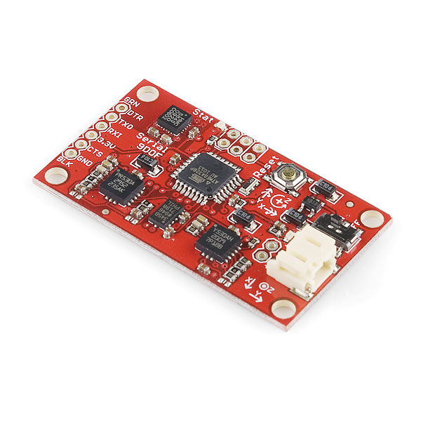
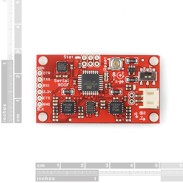
The 9DOF Razor IMU incorporates four sensors - an LY530AL (single-axis gyro), LPR530AL (dual-axis gyro), ADXL345 (triple-axis accelerometer), and HMC5843 (triple-axis magnetometer) - to give you nine degrees of inertial measurement. The outputs of all sensors are processed by an on-board ATmega328 and output over a serial interface. With the work of Jordi Munoz and many others, the 9DOF Razor can become an Attitude and Heading Reference System. This enables the 9DOF Razor to become a very powerful control mechanism for UAVs, autonomous vehicles and image stabilization systems.
The board comes programmed with the 8MHz Arduino bootloader and example firmware that tests the outputs of all the sensors. Simply connect to the serial TX and RX pins with a 3.3V FTDI Basic Breakout, open a terminal program to 38400bps and a menu will guide you through testing the sensors. You can use the Arduino IDE to program your code onto the 9DOF, just select the 'Arduino Pro or Pro Mini (3.3v, 8mhz) w/ATmega328' as your board.
The 9DOF operates at 3.3VDC; any power supplied to the white JST connector will be regulated down to this operating voltage - our LiPo batteries are an excellent power supply choice. The output header is designed to mate with our 3.3V FTDI Basic Breakout board, so you can easily connect the board to a computer's USB port. Or, for a wireless solution, it can be connected to the Bluetooth Mate or an XBee Explorer.
Having a hard time picking an IMU? Our Accelerometer, Gyro, and IMU Buying Guide might help!
Note: This product is a collaboration with Jordi Munoz of 3d Robotics. A portion of each sales goes back to them for product support and continued development.
- 9 Degrees of Freedom on a single, flat board:
- LY530ALH - 300°/s single-axis gyro
- LPR530ALH - 300°/s dual-axis gyro
- ADXL345 - 13-bit resolution, ±16g, triple-axis accelerometer
- HMC5843 - triple-axis, digital magnetometer
- Outputs of all sensors processed by on-board ATmega328 and sent out via a serial stream
- Autorun feature (hit 'Ctrl-z') and help menu integrated into the example firmware
- Output pins match up with FTDI Basic Breakout, Bluetooth Mate, XBee Explorer
- 3.5-16VDC input
- ON-OFF control switch and reset switch
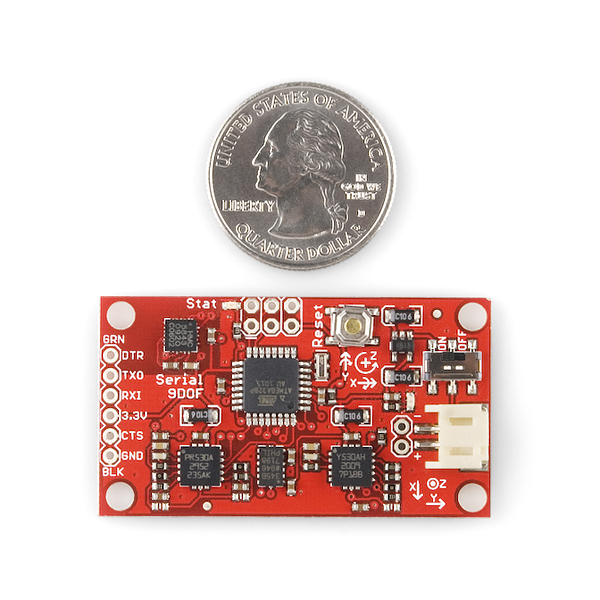
- 1.95 x 1.10 " (49.53 x 27.94 mm)
9 Degrees of Freedom - Razor IMU - AHRS compatible Product Help and Resources
Comments
Looking for answers to technical questions?
We welcome your comments and suggestions below. However, if you are looking for solutions to technical questions please see our Technical Assistance page.
Customer Reviews
No reviews yet.
to RazorConcepts:
I received my 9DOF a week ago and it has a 328 MCU on it.
Using the code from here it works great with the arduino-0018:
http://code.google.com/p/sf9domahrs/
It also works great with the supplied sparkfun code to do some basic verification and edumacation...
anyone with an idea when the current 9DOF was taken out of production, and this new revision post was made ?
I just need to figure out when the new revision would be out and what would be the changes of the new one
thanks
For Dummies! I got mine working. This is what I would have liked to be told:
Download arduino programming environment from www.arduino.cc
Plug in board via FTDI basic, make sure windows finds the serial to USB device
Check com port assigned in Device Manager
Use Arduino serial monitor to check device is working (push reset button on Razor!)
Download Razor code and python code from
http://code.google.com/p/sf9domahrs/
Download Razor code using Arduino:
Set correct board (Pro or Pro mini, 328)
Set correct port
Download Razor code
Then DO NOT follow header instructions in python code as versions have changed
First Install Python 2.7
Install pywin for 2.7 from http://sourceforge.net/projects/pywin32/
Install pyserial from http://sourceforge.net/projects/pyserial/files/
Install Vphyton from http://vpython.org/contents/download_windows.html
Then copy python IMU code into any appropriate directory and run!
Hey JOn;
Thanks for your info.
I have a problem in the following part of your explanations.
Install pywin for 2.7 from http://sourceforge.net/projects/pywin32/
Install pyserial from http://sourceforge.net/projects/pyserial/files/
Install Vphyton from http://vpython.org/contents/download_windows.html
I tried to install pywin using cmd, but it gave me an error.
So far I could run the example file by VIDLE for VPython, although I cannot see any out put because of probably the version (my python is 2.7).
Could you help on this?
Thanks!
Thank you.
I am using the thing only as and AHRS - you can't really use it as a flight computer, it just doesn't have the I/O connections for that. I find the sensors very accurate and most importantly, they don't drift - seriously, you can shake this thing around, it will keep its calibration.
I used the arduino environment to compile the code from http://code.google.com/p/sf9domahrs you can download it form arduino.cc
The 9DoF is non standard in terms of clock speed, so I inserted the following into my platform definition file. In the Linux version of arduino, it is at hardware/arduino/boards.txt in the arduino directory.
[my comment was too long for sparkfun, so I pasted this to pastebin] http://pastebin.com/KAEmPmD2
Then, you have to open the AHRS code in the arduino environment and set the platform to the 9DoF. To upload the code, press the upload button and shortly after that, press the reset button on the board to activate the bootloader.
Hope that helped some folks!
The uploading advice above is outdated for the ATMega328. If you want to run the AHRS code you have to choose: Arduino Pro or Pro Mini(3.3 V, 8Mhz) with AtMega328 as the board to upload to in the arduino ide. Then it works great!
Tks man. I was having a problem reading the data. Tried almost everything, it turns out that the problem was the board.
What did you change to make this AHRS compatible?
see reply to ledshine below
Hy Is the code for the application showed in the video above opensource and available? thank's
Does this sensor has Kalman Filtering ????
The default firmware does not use a Kalman filter.
Hi, I am a new beginner for this 9DOF appliations. I got many questions here as below, and hope to get your help: Question 1: Now we are using the IMU developed by ourselves, this IMU integrate three sensors, including accelemeter, gyrometer,meganetometer sensors. I want to ask whether the DCM source code here could be suitable for our situation to be used?
Question 2: Where is the right open source code could be downloaded to be suitable for us? I seached few times, but not sure which is the right one.
Question 3: What should we process the raw data beofre sending to DCM part? The result from DCM is about some angele, right?
Great thanks.
Tonny
Are The Test Firmware v22 located on http://github.com/a1ronzo/SparkFun-9DOF-Razor-IMU-Test-Firmware usable for this IMU? I can't find the old versions there. Current firmvare uses a triple axis gyro. this one has 2 gyros.
Hi everyone,
I have used ITG3200 and ADXL345 break out (http://www.sparkfun.com/products/10121). I had a very good and stable reading on my old quad, and I was using complementary filter instead of Kalman filter. Right now, I am using the code provided (http://code.google.com/p/sf9domahrs/) and it fluctuate a lot when my motors are running fast. So I started using my own code for ADXL345 and I am not using Arduino IDE, I am using Code vision. My SDA is PORTC.4 and my SCL is PORTC.5. I send the 0xA6 which is the ADXL345 address and I don't receive any ack.
My sensor is working fine with the code provided so it can't be a hardware problem. Do you have any idea what I am missing?
thank you very much.
1.I want to start then I am tyro, please help me to start.
2.I want to connect my imu with ft232 to PC , please send me monitoring software
3.Please help me to develop IMU with kalman filter
4.Where I can download the source code of razor ?
5.We have to upload new Avr code. Is it correct?
Mersi turlan1979@yahoo.fr
The link to the 3.3V FTDI Basic Breakout is out of date and leads a reader to old stock no longer carried by Sparkfun, in fact it is so old that there have been two new revisions of this board since this link was implemented.
When will this be available again ?
We should have a new version available within a week.
I am newer to 9DOF and IMU. I fund Roll and Pitch outputed form the 9DOF is relative angle, then i want ask whether i can get the horizontal absolute angle, and how?
Thanks!
Can this be purchased from anywhere I cant find it.
I bought it here
It has just arrived from China today.
Sorry for my bad english.
and sorry send this question here, I really had looking for my solution, but at the time, nothing simple to use! Its very hard for me, to look all comments and understand, because my english is very bad.
I have bought that 9dof razor imu on other site, because here is out of stock, and now, i will say my problem.
I have to use this board with my seeeduino v2.12 (atmega 168) to stabilise a camera in hard condition ( i will try, that is a work of my university).
I had sucess using FTDI to interface in Python GUI, and in Serial.print to see value of x (accel),y (accel) an z (gauss) using the code of Jordi Munoz.
How can realy read pitch, yaw and roll, to use that values to controll Servos on my Arduino? with RX and TX, I just can see that values, i can not use this values to control any Pins of Arduino. Please, help-me... i know how this tipe of message is inconvenient.
Thank...
It's great that a new revision is coming out, but is anything going to be done for those of us who paid $125 for this defective item?
The new revision replaces the magnetometer because the one on this board is no longer being made, it isn't to fix any defects so if you have a defective item contact techsupport@sparkfun.com
It's unfortunate that you guys are intending to continue selling this product with the well known, and well documented problems that it has. I have to be honest, of the last 6 products I bought that were developed by Sparkfun, 3 have had flaws that made them unusable. I'm sure this comment will be ignored like other similar comments on numerous products on your site. Beware potential SparkFun customers.
This part DID have some inherent problems related to its power supply and the magnetometer. I had a really long set of email discussions I had with your tech support.
The magnetometer malfunctions when the IMU is powered from its own regulated supply. It works fine if you feed it 3.3V directly from some other source, the XBee USB explorer board for example.
any idea when the new version will be available?
There seriously needs to be some step by step instructions for the 9dof which actually work. I've tried to getting it to work via the arduino Mega 1280 and nothing. I just bought an ftdi breakout which came yesterday and still nothing. It sends data to the serial port flawlessly. However, I can't upload jack via the arduino or the ftdi. Now this device is very important for my project and it would be nice if it worked! the error I am getting is
avrdude: stk500_getsync(): not in sync: resp0x72
avrdude: stk500_disable(): protocol error, expect=0x14, resp 0x51
What's the big deal? Uploading data to this device shouldn't be this hard!!!!
Hmm I checked around on the error and it says the PC just isn't communicating with the board. So I checked out the 9 axis and saw a scratch precisely on the Rx line of the 9 axis. Sparkfun sold me a defunct IMU. I'll have to contact their customer service...
This is what you wanted, a step-by-step tutorial
Razor IMU Step by Step Tutorial
The 6 holes on the board that are supposed to be for the ATmega SPI have actualy 3 digital IO ports. These are the MOSI MISO and SCK that we can see on the Schematic. They correspond to arduino's 11 12 and 13 ports. (Also on the SCK (13) there is connected the green LED of the board). So, for as long as we do not use the SPI (i think nobody uses it) we can use these ports as we like ;)
Hope i helped :)
i just started playing with my 9dof, and i found out that in the 6 holes we have 3 digital IO ports! These holes are supposed to be for the ATmega SPI, but actually the SPI on an ATmega connects on portB, this means that when we don't use the SPI we can use these pins for IO!
These are pins PB3 PB4 and PB5 that on an arduino correspond to pins 11 12 and 13. As we can see on the schematic of the 9DOF they are the MISO (PB4 or 12 on the arduino), MOSI (PB3 or 11) and SCK (PB5 or 13) ports. Also on the SCK port there is connected the green LED of the board.
I hope this will be useful to you guyz :)
I posted a small Windows program with minimal dependencies that should run on most versions of Windows from XP SP3 on using WPF that emulates the python 3D display shown above. You need to have the ARHS firmware installed. See http://code.google.com/p/sf9domahrs/issues/detail?id=22
Thanks Zoomer!! This is so much better than having to go thru installing Python...which I was never able to get to work on a 64-bit machine.
It's out of stock. When will it be available on the store again?
I can sell you mine
I do need of two of them and will pay them with credit card. That's the problem. :D
Ok, I have one unit with 3.3ftdi, bought 6 months ago and fully functional. I think I paid about 150 for both but would sell for 105 with shipping. Contact me at sy at yalcin dot us, if anyone.
Hey,
If I connected this chips rxtx to the arduino and pulled out the ATMEGA328 from the arduino, I should be able to read/write firmware off the Razor without an FTDI right? I just wanted to know if that may work before I got myself a FTDI :D
Thanks
Yes it should work, make sure to use 3.3V
I bought this with ftdi 3.3 serial usb but decided to go with hmc6343 and will be selling it on ebay. I see that its out of stock so if you want, I can give you mine.
Just noticed - the accelerometer link in the description section is broken. It points at the ADXL335, but it should point at the ADXL345.
I made a quick step-by-step tutorial for using this IMU and trying the AHRS code here :
http://8p-tech.hopto.org/?p=249&lang=en
I hope it will be helpful!
Hi,
from the schematic it looks as if the outputs from both the LPR530AL as well as the LY530ALH sensor are processed using a HP/LP combination. However, the corresponding (not amplified) outputs (XOUT-1X, YOUT-1X, ZOUT-1X) don't seem to be routed to the Atmega.
I'd like to be able to use the +/-1200°/s measurement range available on these lines. Is there any way to get access to them?
Thanks and best regards
Hey,everyone,I am trying to understanding the AHRS code, and want to modify something for myself .But I get some problem, I cannot understand two part of code ,DCM.pde and ADC.pde, there are some theory in them ,but i don't know about them. Like in DCM.pde ,eq19 and eq20 ,I cannot find them .If anyone who knows about these equations, please tell me ,thank you very much .
I have read most of the posts here and still have the following 2 questions:
1) where can I get the code (pde) that was shipped with the 9 ODF Razor board (just bought it a few days ago)?
I want to be able to restore the board to it's orginal state so I can grab the raw values just like it was sent when I'm done for my next project.
2)I get the following values
$,12,62,237,383,402,366,148,-276,-559,#
$,6,56,232,378,401,367,148,-276,-559,#
$,0,51,232,370,398,366,148,-276,-559,#
$,2,54,237,366,399,363,148,-276,-559,#
$,8,51,218,366,399,360,149,-257,-561,#
What do the values in position 0,1,2,3,4,5,6,7,8,9,10 relate to? (ex which one is speed, heading, pitch, yaw, roll, g's etc)
Thanks for any help you can provide
regarding 1) look for "Firmware Files" under Documents on this page
New to Arduino
How do I compile and upload the firmware?
I do not see a pde file in the zip file.
I also tried installing it as a library in the arduino ide with no luck. Thanks for any help you can provide.
I have written a Tutorial on this, you might want to have a look
http://pranjalchaubey.wordpress.com/2011/04/14/razor-imu/
I really need some help. Trying to do something I think should be really easy...but I am struggling. I know it's ill-advised to determine position from an accelerometer only, but I am trying to create a demo where I can detect that I have moved my board X meters (overall magnitude, so sqrt(x^2 + y^2) is fine. With the board completely still, and running through some corrections from the AHRS project, I get reading such as below.
Acc X: -1.0 Acc Y: -1.0 Acc Z: 248.0,
Acc X: -2.0 Acc Y: 1.0 Acc Z: 248.0,
Acc X: -3.0 Acc Y: 0.0 Acc Z: 247.0,
Acc X: 0.0 Acc Y: 1.0 Acc Z: 245.0,
Acc X: 1.0 Acc Y: -1.0 Acc Z: 246.0,
Acc X: -1.0 Acc Y: 1.0 Acc Z: 248.0
First off, does the sensor think it is reading -1m/s^2 in the x and y coords for the first case? Also, with that much fluctuation, how can I ever get a reading worth using? Thanks for any help!!
Hi, I would like to know what is the frequency of the output stream? I use default settings 38400-8-N-1 with v.18 firmware board version. I measure time intervals between each line and they vary between even less then millisecond to around 0.04. The average is around 0.012s.
I do not have enough skills in MCU handling that's why I am asking for a help!
Not sure. Standard TTL/RS232 Asynchronous Serial is 9600 so try use that as your default
Is this board compatible with Ardupilot Mega? Please reply.
Hello friends...
i am using 9dof imu board....i have installed arduino 18 and python....blinking test code is working....but i m facing problem in uploading AHRS code...its showing types.h no such file or directory.....please help me...how to add directory of i2c,types & defs.h in the arduino 18??
thank you in advanced...
Hi,
Could someone please point me to the original code that came in the 9DOF. I uploaded the AHRS version but its not the right one for me. All links in these comments seem to be for the 16MHz version. I just received the 9DOF a couple of weeks ago and I think I have the 8MHz version. How can I tell which version I have?
Any help would be appreciated.
I am trying to interface this IMU with my laptop as is shown in the video above and am completely lost. When I plug it in via USB port using the FTDI basic breakout. My laptop sees the FTDI basic breakout as new hardware, but that is where things stop. Any help is appreciated.
There didn't seem to be much lag in the video, but does anyone know how many times a second this outputs new data? Hz? Thanks
I updated the firmware, so that I could get the IMU to work with an xbee.
Well...it worked on my serial port before the update. It would initialize, give me the menu, and the data made sense.
Now it does this through my serial port:
http://code.google.com/p/sf9domahrs/issues/detail?id=18
(I tried firmware 1.1 and 1.0)
I should note that I bought the IMU 1 year ago. Not sure if that matters
What are the 6 through hole connections on the side of the board, right by the arudino? Are they unused inputs/outputs? Struggling to find them on the schematic, and they don't seem covered anywhere.
I just spent 7 hours trying to get mine to work, and it's not outputting anything at all. It makes me sad, I hope it's not defective.
mmmmmm! Same problem as me. No serial comms at all! Might be a bad batch.
They sent me a new one and the new one works just fine. Probably was a bad batch.
One design flaw I've come across with this board; when powering it from the header interface I have to add an additional 30+ degrees correction factor in addition to my local declination to get it oriented to true north. I think I have discovered the source of this offset. Near the magnetometer (between the comm header and SPI programming connections) there is a power trace. I did notice that there is a grounded plane on either side of it. However, unless there is an equal and opposite current flowing parallel to this power trace there would be a magnetic field setup in a plane orthagonal to this power trace. Others thoughts on this subject are welcome!
Without getting into it too deeply would anyone have any comments on whether to pursue this or the IMU shield for UAV development?
The other option ( http://store.diydrones.com/product_p/br-0013-01.htm ) has some extra bells and whistles but I'm more interested in component choices and overall system accuracy/precision.
Any inputs?
Does anyone know how to modify AHRS code to calculate position and velocity in 3D translation or full 6DOF displacement?
Hi, I have a 1"x 1" small PCB that does 6 degrees of freedom on batch PCB.
http://batchpcb.com/index.php/Products/51805
I2C interface
total BOM < $25
Thanks Niz..... have you built something around this board? I am interested. Also surprised at the cost of more modern gyros and accels. I just want to make sure accuracy is still decent and the board is tested...
prompt me please formulas for determination of pitch and roll using x_accel,y_accel.....,y_mag,z_mag
I am working on a project where im using multiple Razor boards to measure orientations of the human body. Think of it as a simplistic motion capture system.
Therefore I need to aquire data from several Razor boards and gather them on a Netduino. My problem is that I havent got more than one serial port on the Netduino, and I would like to save that for debugging.
My idea was that I could have the AVR on the Razor board output I2C on two unused pins. Effectively making the AVR an I2C bridge. I need to have two I2C busses, to avoid address conflicts between sensors on the Razor boards. As I understand it they have static addresses.
I would like your comments and feedback. There might be better ways, and it might not be possible at all.
Im thinking can I do I2C on 2 generic pins?
And is it possible to have two instances of Wire.h coexisting?
I am aware that it would require some modding of the board, but im willing to do that.
Kind regards
tax
Just purchsed my Razor IMU - added a header, connected 3.3v FTDI cable, and have data showing on com port through hyperterminal.
Mag data looks good, gyro data looks good, however the accelerometer data shows as 0,0,0, no matter what is going on with the Razor IMU.
As I have not really done anything yet, should I try anything else? Or is this some defect/issue?
Thanks for the help!
hi, anyone know, how to read gyro reading?
Интересно узнать данную штучка в действии, можете порекомендовать её аналоги, а-то что-то много негативных отзывов о данном компоненте... спс. :)
hi!
Baud rate seems bad !
Hi,
My interface with python is working fine instead of uncalibrated data i am receiving. How to calibrate, anyone has an idea?
Furthermore, whenever I reset my razor IMU, it just deletes the first calibrated data and fix the position of the IMU as 0,0,0 coordinates (although it is not). So my questions are; how to calibrate the IMU? And how to save the calibrated data once it is set?
Hello ( sorry for my bad english, i'm french)
I bought this item, and a FTDI 3.3V Breakout.
The Firmaware version is "9DOF IMU software V18"
I install "Arduino 0022" and upload "SF9DOF_AHRS_1_1.zip"
Change Com9 by Com3 in python file and it run find.
hi everyone, i got a big problem here.
I already bought this 9dof sensor and 3.3V FTDI Basic Breakout. I run this sensor in arduino software using the code in
http://code.google.com/p/sf9domahrs/downloads/list (SF9DOF_AHRS_1_0.zip).
the output data works fne, except the euler angle of pitch and yaw is not correct. could anyone help me with the code? why the pitch and yaw angle is messed up whilst roll angle is quite fine??
thanx in advance
Hi folks,
I wonder if someone would be good enough to advise me on whether the AHRS code found here
http://code.google.com/p/sf9domahrs/
would fit on to the ATMEGA168 chip, also bearing in mind that it is already loaded with the boot loader software.
It seems that the latest batch of 9DOF Razor IMU boards are fitted with the ATMEGA168 chip rather than the 328 :(.
Thanks,
Shaun
Has anyone measured the power consumption on this board?
Hi I've bought this 9DOF through my local supplier and used it on my quadrotor to sense and control the attitude and heading. It worked fine initially, but after I've used it for some time I noticed that the heading control is not functioning well. So I connect it to my laptop using the 3.3V FTDI and run the python code to check the attitude and heading output. The heading output was not stable and it was flickering.
So I told my supplier about it and exchanged for a new one. The new board worked well, but after a few weeks the same thing happened again. However I continued to use it for attitude readings as it was still giving stable pitch and roll output. And today after I powered up my quadrotor I noticed the green LED on the 9DOF blinking randomly while the quadrotor is on the ground. I thought that it should only turn off when the gyro saturates so I used the python program to check again. And this time even the attitude data becomes unusable.
My friend who's working on a coaxial heli used the same 9DOF board so I borrowed from him and compared with mine. I've uploaded a video showing the output of the faulty board using the python code: http://www.youtube.com/watch?v=bbNB4Rt-QXs
I'm using the SF9DOF_AHRS_1_1 firmware from here: http://code.google.com/p/sf9domahrs/downloads/list
Please I would like to know if the 9 Degrees of Freedom - Razor IMU – AHRS compatible sku: SEN-09623 cames with every thing that is required – including the software – to be used as a attitude reference on a UAV.
Thanks for your help
Luis Gonzalo
I got it working thanx JonT for very precise instructions.
I just bought Razor IMU 9DOF with USB to serial board it works with Hyperterminal on XP, please guide me to get exe file to make it work on PC (like on the Tube video).
or anybody has information where to get this file I do not have complier for code..... http://google.com/p/sf9domahrs...please help
I successfully flashed the part that comes with the ATmega 168 and I'm getting very inaccurate results (or so it seems). Can anybody check my story here?
has anyone tried to use the heading angles and the accelerometer data to project accelerations onto an earth fixed frame? Then these values could be integrated to get velocity and, if the noise isn't too bad, position?<br />
I recently had a similar problem and found the paper at: <br />
http://delivery.acm.org/10.1145/1470000/1460250/a18-torres.pdf?key1=1460250&key2=8763761921&coll=DL&dl=ACM&CFID=598080&CFTOKEN=28135307 <br />
to be helpful. Didn't get it to work (had trouble since there were magnets interfering with my IMU), but when I picked accelerations and gyroscope values, they followed expected/calculated paths
has anyone tried to use the heading angles and the accelerometer data to determine accelerations in an earth fixed frame, that could then be integrated to get velocity and position?
Hello,<br /> I�ve just bought the 9DOF-Razor board and connected it to my PC via serial cable. Here are some outputs :<br /> -49,70,213,376,383,375,438,96,-184,#<br /> -49,71,215,375,383,374,438,96,-184,#<br /> -49,71,214,375,383,375,438,96,-184,#<br /> -49,72,215,375,383,374,438,96,-184,#<br /> -50,74,213,375,383,374,438,96,-184,#<br /> It is my understanding that these are raw data from the sensors. Could you explain which is the value of Gyro, Accelerometer, Magnetometer? How do I convert these raw data into 3 axis reading? It�ll be a great help if you can give me an example.<br />
Just received Razor IMU board. I am new to Arduino. After building SF9DOF_AHRS I attempt to download and receive the following error:<br />
<br />
avrdude: stk500_getsync(): not in sync: resp-0x0c<br />
avrdude: stk500_disable(): protocol error, expect 0x14, resp=0x0c<br />
<br />
The test firmware over serial port works fine.<br />
<br />
I get the feeling I am missing something really basic here about uploading to the board, however I checked the troubleshooting guide and nothing obvious stood out.<br />
<br />
Any ideas?<br />
<br />
Thanks,<br />
Dave
Hi All,<br />
I recently bought this product. I am trying to see the output on a PC using terminal program. I havent changed the firmware. Can I connect it directly to the PC using a serial-to-usb connector? what is the baud rate the terminal program should be set to?<br />
Please help.
I'm getting intermittent values of 255 from the accelerometer, but only on the y axis. Has anyone else seen this?<br />
i get the 9dof sensor, then i try to upload 9DOF AHRS with ardu duemilanove then set "Arduino Pro or Pro Mini (3.3V, 8MHz) w/ Atmega328" and arduino program said done uploading but when i try in serial with baut rate at 57600,the yaw pitch and roll didn't show.anyone have any solution? thx
I've got sf9domahrs running on my board but getting the python interface installed has proven to be impossible on 64-bit Windows 7. Python itself installs but I cannot get pywin, pyserial or vpython to work with Python 2.7. Is there a simpler test program available that I can use to visually see the output of the AHRS?
If you just open a terminal to the correct port with the baud set for 57,600, do you see readable output? The data is a series of lines like this:<br />
!ANG:-3.56,-3.39,92.35
I get it to read output for baud rate 38400 through a standard window. When I tried it on the python code, it gave:<br />
<br />
,29,-265,14,373,375,367,-129,666,-4,#<br />
<br />
<br />
Invalid line<br />
<br />
Traceback (most recent call last):<br />
File "\filer\jrumack\ms_windows\cpsc_redirected\Desktop\IMU_Razor9DOF.py", line 114<br />
L1.text = str(float(words[0]))<br />
ValueError: could not convert string to float: <br />
<br />
any ideas?
Can you be able to solve this problem. Because I am experiencing very much the same problem. Anyone knows how to fix this?
oops, sorry, that was meant for one post above
I recently got the board, along with an FTDI Basic and miniB cable to plug into my USB. I tried testing it using the python code given from the code base, but it never reads any of the information. I made sure to change it to the right com serial port, but I only get junk. Any ideas what's wrong?
I'd like to access accel values projected onto the earth frame. I suspect the DCM code already has this functionality built in somewhere, but I am having a difficult time following all aspects of the code. If this functionality is built in, what is the variable name for it?
I got raw data from the IMU but what does the values meen?
Like for the last 3 (magnetometer I guess) what do the values meen?
Has anyone added the arduino code for the magnetometer offset nulling?
I just got my Razor working with the XBee Explorer. I was having trouble getting the baud rate correct. I found that I was setting the board to the wrong type. I have the 328 and the correct board setting (Tools/Board) is "Arduino Pro or Pro Mini(3.3v, 8 MHz)w/ ATmega328". It works with the baud rate set to 115200 with the Python display code. I also did have to change the baud rate in the python code.
Mine worked with the baud rate on the XBees set to 57,600 (this is +++ATBD6[enter]) The SF9DOF_AHRS.pde code sets the IMU to output at this rate.
I have rewritten the original SF9DOF_AHRS V1.1 code and re-included the features of V1.0 while still allowing it run on the Atmega168. The free running update rate with representative binary attitude output is ~160Hz. I did this as part of an evaluation for use in future implementations of UAVX.
The code is at:
http://code.google.com/p/uavp-mods/downloads/list
Having an I2C connector would have been VERY useful if that can make its way into future versions of the board:).
Greg
Hi;
Does it work for ATmega328 too?
Thanks
Hi,
I need to code Kalman filter on this unit.
Can anybody help me?
Best Regards
Oops. Meant the CHR-6dm. My bad.
Heh. You and everyone else. Check out the CH Robotics CHR-6d firmware.
http://www.chrobotics.com/index.php?main_page=page&id=3
The chr6d_states.c file is what you're most interested in.
Is the ATmega chip the 328 or the 168 on the stock as of 7-Oct-2010? The last two that I bought had the 168 (during the time that the 328 was unavailable).
The university that I work with would like to buy a couple of these, but they want to be able to change the program. The 168 is full with the AHRS code and they really do not want to change the chip.
I bought one on 3Oct, ATMEGA chip is 328. Be happy:)
Does any body have any documentation for the concept of written code in Python (IMU-Razor9DOF) for those who doesn't know this language?
http://code.google.com/p/sf9domahrs/downloads/list
I already learn some of the syntax but it is very useful to know the pseudocode first.
Thank you
I'm part of a team at the University of Maine that is making a Human Powered Submarine for ISR11. We plan on using an auto-pilot system but don't have much experience with gyros, accelerometers, servos etc. We plan on using a National Instruments cRIO 9022 as our controller. Is this compatible with the Razor IMU? Can anyone provide some books/websites or other references that can help us with making the connections between our controller and various sensors and servos? Any help is very much appreciated!
Hi Everyone,
Do anyone know whether or not can we increase the frequency of the loop that the firmware is operating? Right now its 50Hz in the code that i downloaded from http://code.google.com/p/sf9domahrs/downloads/list. I need to increase it to 100Hz, is that possible or this frequency of operation was chosen under some constraint?
Any help will be appreciated.
I am getting ready to send my board in for repair/replacement. When doing a self-test I always get the magnetometer returning 'BAD', tech support tells me that this is normal. However when looking at the magnetometer output, X and Y appear to work fine while the z-axis is reporting values from -650 to -700. The z values on the magnetometer do not respond to rotations about the z-axis.
Any ideas before I send the board back. Thanks!
Very unhappy I2C bus, at least on this sample of one that I have here.
It looks like the board is depending on the 50K pull-ups that are internal to the magnetometer and that is way too much to run a 200 Kbps I2C bus. I'm seeing a rise time (standard 10%-90%) of more than 2 usec, twice the maximum for a even a "standard mode" 100 Kbps I2C bus.
The accelerometer (which shares the I2C bus) seems to be okay with it but the magnetometer isn't talking. Maybe it's dead but I suspect that tagging the SCL and SDA lines with 7.5K or 6.8K will do the trick.
Just to follow-up on this ...
Tagging a couple 6.8Ks to the SCL and SDA lines helps a lot to clean up the appearance of the I2C bus. There's plenty of room to superglue a couple of 0805s to the soldermask and then add some "field change" 30 gauge wires to the processor pins and also to 3.3 V.
The issue with the magnetometer seems to be that it really, really wants a full power cycle or else it can get hung at a fixed value (32 in my case; don't know if that's universal). It wasn't an I2C bus problem but I'm happier now that the bus looks right.
Hi Rawebb, I had the same issue with the magnetometer. (values is constant at 32, even if I recycle power). Did u manage to fix it ? Is there any effect from soldering external I2C pull ups to the magnetometer behavior ?
I'm testing a new 9DOF Razor IMU (sku: SEN-09623). I bought it in Italy few days ago.
My suspect is integrated LPR530AL 2 axis gyro is not working properly.
I'm testing it using original firmware, viewing gyro sensor data.
Moving the board, the value of Z axis gyro change only. X and Y axis (LPR530AL chip) values don't change when i move board (fast or slow) in any directions.
Accelerometers and magnetometers work correctly on any axis. Gyro works on Z axis only.
X and Y gyro displayed values usually start from a around 400 and they decrease to 0 in few minutes after power on, regardless board movement.
Connection used : serial RX/TX, GND and 3.3 pins only. Board is connected to (and powered by) my pc using FTDI breakout.
Is it dead ?
Does anyone know if there is a way to tap into a pin for input (i.e. a button, or even a infrared sensor)?
I am a beginner so reading the schematic could take me forever.
Thanks.
Am using this board to make a flight logger for gliders flying aerobatics (full size gliders).
Just wanted to say am impressed so far by the board.
Have completed the initial firmware to allow calibration of the board accelerometers and the results are as good as much more expensive IMU's. Have not finished the gyro cal routines yet but some quick tests show drift rate after initial bias correction to be below 1deg/min.
A real bargin compared to some of the $1000+ units once it is correctly calibrated.
Example accuracy of board after 14 point1G tumble cal)
Offsets
-15.171142 -7.42442 25.0406
Calculated axis misalignments (degrees)
X= 0.066 Y=-1.094 Z= 0.358
Max X Error 5.479 at cal pos 9 (0.558%)
Max Y Error 4.096 at cal pos 13 (0.418%)
Max Z Error 7.242 at cal pos 5 (0.738%)
Total error using 14 positions 95.098 ave error 2.264
If you don't want to post code, I would appreciate a reference to the calibration algorithms for both accelerometers and gyros.
John Abshier
Any chance you could share your code? Is it arduino or AVR?
On the 9DOF AHRS code, i would like to have the magnetic bearing information in the output stream. Anbody know how I can add that?
Anybody notice it takes about 400 or so outputs to stabilize from power up (the first 400 samples or about 10 sec worth of data are ramping to a limit if the board is powered up and left still)? Any idea why? Is it just the complexity of the math pipelining it's way through all the calculations to the output? Can anyone get rid of this initial drift other than waiting?
You probably could do it by changing the PI gains for the first tens of samples to ramp up the integrators faster.
Can anyone help me?
1. How can I backup the firmware?
2. How can I upload the Test Firmware?
I am completely new to this so I'm sorry if the question seems dumb.
Thanks
You can program this just like an Arduino,using an FTDI basic. Check the forums, there is a lot of discussion about loading code there.
I'm sorry. I am really not familiar with this. When I download the Test Firmware it looks like a C program file. How can I compile it and upload it to the board?
Thanks
No problem. Contact tech support at techsupport@sparkfun.com and they can help you.
Hmm... I just got one of these sensors. I flashed it to the AHRS code and tried to read it with the Python GUI. the big problem is that the sensor is amazingly off and the numbers it's returning are very, very jittery, or at least that's how the GUI made it look.
Anybody know what I'm talking about?
I'm having a similar jittery problem...<br />
<br />
I have:<br />
<br />
- AHRS code on 9DOF, modified to continuously output euler values at 115200 baud.<br />
<br />
- Bluetooth Mate soldered to 9DOF header, sending 12 byte frames of data to a computer.<br />
<br />
- Simple computer-side debugging program in c to receive and display the data.<br />
<br />
Sometimes it pauses and then seems to make up for the pause by spitting out a ton of data at once, and sometimes it just stops entirely.<br />
<br />
I wonder if it may be the 9DOF slowing down since I have it sending data as fast as possible?<br />
<br />
Perhaps I should be using raw input mode instead of canonical mode when I initialize my terminal to receive the data?<br />
<br />
Does anyone have experience with streaming as much data as possible via bluetooth?
Hi all,
I'm trying to connect the Razor 9DOF (AHRS firmware v1.1) to an OpenLog v1.61 module. At 19200 bps everything works as expected but if I change the AHRS code and OpenLogs config.txt to 57600 bps it doesn't. The data is not completely corrupt as what happens if the baud rate is completely wrong. I can still see part of the data columns but it's riddled with a lot of strange characters...
Any idea what happens here? I've selected "Adruino Pro or Pro Mini (3.3V, 8MHz) w/ ATmega328" in the GUI...
Anybody notice the pitch value range is only shown between -80 degrees and +80 degrees? Does anyone know why? Why doesn't it work between -180 and +180 like the roll and yaw?
Pitch should have a range of +/-90 degrees. After you pitch past vertical (90 degrees) your roll and yaw value should swing 180 degrees. A pitch value of 100 degrees is measured as a pitch of 80 degrees and inverted flight (roll = 180 degrees). Another example is a pitch of 180 degrees (upside down)...this is measured as a level pitch (0 degrees) and a roll of 180 degrees. Hope that helps.
This arrived the today. The test software seemed to work fine, and I have loaded the ahrs software on it.
Myproblem is that it blocks while trying to talk to the ic2 bus.
Following Code Lifted from the i2c module of ahrs.
Serial.println("Start AccelAddress");
Wire.beginTransmission(AccelAddress);
Serial.println("Start Send");
Wire.send(0x2D); // power register
Wire.send(0x08); // measurement mode
Serial.println("End AccelAddress");
Wire.endTransmission();
Serial.println("AccelAdress Done")
I get all the serial messages excpet the last one. Seems to block when it executed Wire.endTransmission.
Driving me nuts. I tried loading the factory test firmware back and thats another story :).
Hi, I?m a newbie and am a little stuck. I have just purchased a 9 DOF Razor IMU and a 3.3v FDTI breakout which I?m powering via usb.
I?m planning on building a C# application to measure tilt but can?t understand the values received from the accelerometer.
If I hold the board flat I get a reading of 0, 0 on the x and y axis?s. If I rotate the board 45 degrees on the x axis I get a value around 150. If the board is held at 90 degrees I get a value of 269. I also receive the similar negative values if the board I rotated the other direction.
What are these values I?m receiving? Are they Volts, G?s, Newton?s or something else? How do I go about converting these values to accurate angles.
Any help would really be appreciated
Cheers
Well... let's break it down...
The angular sensors are +/- 180 degrees. That gives a 360 degree span. The output is in ADC bits, from 0-1024 (data sheet shows it is a 10 bit ADC).
So, to get the right value, you can use the formula (for degrees):
Angle = (360 / 1024) * ADC Value
Which for your two examples, gives:
Angle = (360 / 1024) * 150 = 52.734 degrees
Angle = (360 / 1024) * 269 = 94.570 degrees
The span is arbitrary, if you wanted volts, replace 360 with 3.3. If you want radians use 2*Pi, etc.
Can you please confirm if I've got this right.
for gyro deg/s
sensitivity = 0.83 // as per datasheet
zeroLevel = 1.23 // as per datasheet
degPerSecond = (gyroX * 3.3/1024 - zeroLevel)/sensitivity
angle = degPerSecond * elapsedTime + previousAngle
I too am interested if samoc's calculation is correct. If it is, then I'm getting -365 to 600 degrees per second instead of +/-300 as I'd expect based on data sheet. I am spinning board in both directions and purposely trying to saturate the sensors, but I expected them to saturate near +/-300 degrees/sec. Also, is there any way to get the 1X range of +/-1200 deg/sec so I can measure higher rates than +/-300?
Awesome, thank you. Can i ask how i would go about converting values received from the gyro to degrees/s or even better to actual angles.
When the board is laying flat i am getting readings of 377, 374, 380;
Cheers
Is there any posibility to conect a GPS?
hello!! there are some free pins that i don?t know what they are for. Is there any posibility to conect a GPS to those pins??
Most GPS modules output standard NMEA strings of data over a UART. Use the pins labeled TXO/RXI if you want to connect this to a typical GPS module.
I have investigated and I think the pins are for SPI protocol.
The 2x3 header is for SPI communication yes.
The 1x6 is for serial communication. You can use the 1x6 header to connect to a gps module such as the following:
http://www.sparkfun.com/commerce/product_info.php?products_id=465
http://www.sparkfun.com/commerce/product_info.php?products_id=8975
http://www.sparkfun.com/commerce/product_info.php?products_id=8266
What these module have in common is a serial data output. This 1x6 header is also used to upload Arduino Sketchs or other code that uses a serial bootloader.
You certainly can use the SPI header to talk to a module that uses an SPI interface if you don't want to use the serial link.
Could you guys add the eagle files for this? Thank you
Hello Arduino Experts,
I wonder if it is possible to read from ADXL345 at 100 Hz rate (0.01 second). I have checked the code given above "Code by Doug Weibel and Jose Julio" and it works fine for 50 Hz.
Can any one help or suggest a solution or may be this is not possible using the Razor IMU board.
Thank you very much.
So I've now tried just a plain old FTDI breakout cable (besides the bluetooth module) using both Hyperterminal and Putty. Rubbish data output only, time to get another one (haven't done anything to let the magic blue smoke out).
I'm a noob, got it working. Flow control to RTS/DTS @ 38400 bps
Just got the Razor IMU board. Hooked it up to bluetooth mate. I had no problem establishing the connection at 9600 baud, or 38400, or 115200, but I haven't been able to receive any useful data from Razor itself. When I reset the board, I get a sting of symbols through the serial port (a combination of "?" "?"), and that's it. No other kind of data.
As far as I understand the board should be pre-loaded with testing firmware. How do I communicate with it? Is the firmware missing, am I doing something wrong or is one of the components defective?
I'd upload a code to the board to fully test the serial communication, but I fear overriding the test firmware sketch.
Don't know if you ever sorted this out, but that sounds like a baud rate mismatch to me!
Just getting started here. I've hooked the SF Bluetooth module to the SF 9DOF and succesfully connected the SF BT module; however, I'm getting rubbish output in hyperterminal. Anyone have any ideas? I see below someone connected the "grounds" together, could someone explain further? Thanks!
After 6 hours of tinkering I finally got the device to work!
The issue is with bluetooth mate's baud rate being different from Razor's. You fix it by going into the terminal window (the same one spitting gibberish).
Type "$$$" - command mode for the bluetooth mate. The terminal should respond with "CMD".
Type "SU,38.4" and hit enter. The terminal should respond with "AOK" indicating that the serial connection on the Razor end has been successfully set to 38400 baud. If the terminal returns "ERR", check spelling.
Type "---" and hit enter. The terminal should respond with "END".
Cycle power.
You should now be able to see Razor's firmware. Now that the data stream is active, you will no longer be able to go into bluetooth mate's command mode without disconnecting the TX and RX pins. If you choose to program your own sketches that utilize different serial baud rates, then you'll probably have to go through the same process - first updating Razor, then bluetooth mate's baud settings.
What does your rubbish data look like? Mine's a combination of "a" and "u" characters. I looked up on youtube what the testing program should look like. http://www.youtube.com/watch?v=SIYj0tMy-Is at 0:16 mark looks like the menu.
I tried sending commands that the menu would respond to if it was active, with no success. The only time I get any data from the device is when it's powering up.
Hi, I'd like to use this product in an automotive environment to gather live dynamic car attitude data (G forces, braking strength etc...).
Is this IMU suitable for this purpose?
Is the accelerometer fixed at +-16g sensitivity or is it programmable?
Thanks!
Hoping SFE can clear out some doubts for me
!.) With the default test FW, the Gyro readings are from the 4x mode right?
2.) Though the 3 Vref values of the gyros are connected to ADC pins of the 328, they are not used in the test FW code, right ?
3.) using the test FW, the gyro value when the razor is still (please tell me whether my calculations are correct)
zero rate level(from gyro datasheet) = 1.23V
ADC - 10bit covering full 3.3V range
Therefore zero rate output = 1.23 / 3.3 * 1024 = 382
But the zero rate op i get practically is about 260 - 270
Am I missing something here ? Hope you can help with this
D
Hi, I've just received your IMU and I'm going to test it.
I studied carefully your AHRS code and I'm very impressed about simplicity and accurary (theorically).
I've a lot of question to ask, but now I start with the first and second only:-)
Q#1: Have you try to use same accelerometer output for twice integration to estimate position ?
Q#2: Do you think it is necessary to use a second kalman filter matrix to correct accelerometer output errors?
My goal is to upgrade your IMU/AHRS in a complete INS.
Thank in advance.
I'm working on a project with similar requirements (position estimation). If you want to share ideas, let me know and I'll send you contact info.
Does anybody can tell me the power consumption of this thing ?
Thanks
Firmware for idiots!!
I have the razor and an Arduino Duemilanove. I've downloaded everything and read everything online, but I can't for the life of me figure out how to update the firmware. What do I do with the Makefile or main.c? Do I use Arduino sketch, Programmers Notepad 2, or avrdude? Are there any other connections required between the Razor and Duemilanove other than Gnd, Tx, and Rx? A step-by-step guide for morons would be GREATLY appreciated.
Thanks - JAFM
Is it possible to use it without the DTR, CTS pin connected?
Hi, I can't understand a small part of Jordi's code. He says that use an oversampling tecnique for increase ADC resolution but if he cumulate analog value in the Interrupt Service Routine (ISR) how does he update ADCH and ADCL registers? He should exit from ISR and when the next conversion has finished and and new interrupt occur then sum the new value to previous in the ISR: analog_buffer[MuxSel]+=..........;
I don't understand.Can someone help me?
thanks
i have buy the 9 Degrees of Freedom - Razor IMU - AHRS compatible and the Breakout Board for FT232RL USB to Serial
I had conected both of their and then with the compiuter to see in the terminal the result. anything happen, in the terminal I din?t see nothing, even the tx and rx leds to the Breakout Board for FT232RL were switched of.
i make anithing wrong????
any body can helpe me??
thanks
@ Sparkfun experts...
How can i interface the IMU to an Arduino serially. what to do whit the DTR and CTS pins as leaving them open doesn't make Arduino to read data from IMU? IMU is working fine with PC.
Thanks!
Hi, Can I connect the Razor to the PC USB port and program it, (via the bootloader) using the FTDI cable ? or do I specifically need the FTDI breakout board for that ?
You can use either. You may need to manually reset the 9DOF though, since the cable doesn't reset after programming.
Hello,
is it possible to connect directly the 3.3v UART of the Razor to a 5v UART of a processor?
Yes, but it's not necessarily guaranteed to work right. Some controllers like it, some don't. You may need a logic level converter. We sell 'em, and they're cheap.
Somewhat answering my own question. I can get connection to the board using the Atmel JTAG ICE Mkii and a squid cable, so now I know the ISP is active. Still cant talk to it using a Polulu AVR programmer, but I can sort that out later.
Different question. I used the Arduino AHRS code, and it compiled and uploaded ok with the Arduino bootloader, but the main output seems to be garbage, no recognisable characters at 57600 baud. Must be something else wrong.
Have you tried different baud rates?
"You can use the Arduino IDE to program your code onto the 9DOF, just select the 'Arduino Pro or Pro Mini (3.3v, 8mhz) w/ATmega328' as your board."
Make sure you select Pro or Pro Mini 3.3v, 8mhz.
Can anyone confirm whether the ISP system on the Razor is enabled or not ? I tried a read of the AVR signature bytes with an AVR ISP programmer using AVR Studio, and just got a connection error message. I want to use the ISP, since I need to program in some non-Arduino code.
If we program the 9DoF IMU with http://www.sparkfun.com/datasheets/Sensors/IMU/9DOF-v11_firmware.zip
we loose the previous FW that is already there on IMU, I would appreciate Sparkfun, if it upload source of that preloaded FW also.
Is anybody have that preloaded FW ?
Sorry about that. The v11 firmware is back up on the product page.
-Aaron
That should be the firmware that ships with the unit, unless you have an older unit.
Once I can get this compiled how do I flash the compiled code from 9DOF-v11_firmware.zip to the device? I am using OS X.
Edit: Would it be similar to this? avrdude -p atmega328p -P COM1 -c stk500v1 -b 57600 -Cavrdude.conf -U flash:w:main.hex
I'm trying to log the 9 dofs with the Openlog. The Openlog doesn't have the option of 38400 baud rate. So I have to change the Razor imu to 57600. How do I do that?
...I have no experience with arduinos.
Thanks,
Benjamin
Hi Benjammin,
1. Just download SF9DOF_AHRS_1_0 and arduino-0018 IDE to compile and connect IMU via USB breakout board to PC.
2. In the "SF9DOF_AHRS_1_0" you will see this
Serial.begin(57600); You can change the baudrate as
you want.
3. Use the "Upload" button in the toolbar. Thats it.
Now you can open your terminal program at 57600 and see the data.
Hi, I'm working with Benjamin
The code doesn't compile as written...
What errors are you getting ?
In function 'void setup()':
error: 'Analog_Reference' was not declared in this scope In function 'void loop()':
if this was based on a PIC32 I would consider it interesting.
Hi
Just download SF9DOF_AHRS_1_0 and used arduino-0018 IDE to compile and upload sketch to IMU via USB breakout board!
When I run the serial monitor, set to 57600 baud, I get rubbish.
COM3 is set to 57600,8,1,none. I get the same result use terminal software too?
I can see in the code the Serial.begin(57600); so I dont understand why I'm getting rubbish output??
Please help!
When you upload to the board, make sure you select Pro or Pro Mini (8mhz, atmega328). This changes the timing. That should work.
Hi
I have just wired up my 9dof imu to a serial port and have selected option 3 from the boot menu.
I am typicaly seeing values like this one :-
x= 377, y= 364, z= 548
I'm real new to this, but expected that these values would be degrees, i.e. 360 or less?
Whats values am I seeing??
Thanks in advance!
I think...
whatever the range is 0-360deg or 0-16g, it is broken into 1024 steps if the signal has 10 bits resolution (2^10). A lot of these low-end IMUs only have 8 bits resolution so the reading is always between 0 and 256 (2^8). Then you have to convert that into something with physical meaning like Gs or degrees or degrees/s.
...i think
I have just bought this product in order to connect it to an ARM microcontroller to make a inertial measurement system. I havent bought the 3.3V FTDI Basic Breakout. So I would like to know if there is any way that I can use the serial interface of the AHRS to connect to a RS232 port.
There is any document describing this product in a technically detailed way like for the 6DOF?
Thanks
I am considering buying the Razor IMU and am new to electronics and programming.
Which components are necessary to program the sensors on the Razor IMU? Are the FTDI basic breakout board + cable the only additional components needed? Do I need to purchase a separate programmer board? What software will I need to download to accomplish this? I'm unfamiliar with Arduino products, etc., so specific information would be greatly appreciated.
My plan is to first solder the Razor to the FTDI basic breakout board, do the sensor programming, then desolder and connect the Razor to the Logomatic for several measurement events.
Thanks a lot for your help!
Hi pica,
Yes, you can do that what you said. Only FTDI basic board+cable to PC. that's all.
download Arduino IDE and program the code provided by Sparkfun .I think, you need to take out some serial print commands if you want to use this board directly to your other boards.
Does anyone know where i can get phyton code for 9dfo show in the youtube ?
Python GUI:
http://code.google.com/p/sf9domahrs/downloads/detail?name=SF9DOF_AHRS_interface_python.zip
The schematics shows both Magnetometer and Accelerometer
are connected to ATMEGA328( TWI(I2C)) using SDA , SCL pins.Am I right ? Schematics are Confusing me.
If i want to utilize the tapping functionality(single click,double click mouse functionality) of accelerometer, How to do that ?
If taping is possible, any problem with AHRS code ?
Any idea is appreciated.
Yes, the SDA SCL lines are shared by the accelerometer and compass. I2C is designed so you can connect multiple devices to the same data bus.
Take a look at the example code for the ADXL345. It is a good starting point:
http://www.sparkfun.com/commerce/product_info.php?products_id=9156
Thanks N8B. So they are like multi slaves on I2C bus.
On the verge of buying the 9DOF, I have a few questions and hopefully someone can help me with them
1. is the bootloader issue (having the 168 instead of 328 bloader) now fixed ?
2. Why did SF do away with the 16MHz and went down to 8MHz. Can I upgrade the "razor" to 16MHz ?
There is another kind of FW that was mentioned but it was actually developed by the guys from DIYDrones, which is the AHRS FW (http://code.google.com/p/sf9domahrs/).
The main diff between the 2 kinds of FWs are that FW vers 11, 15, & 16 are from SFE and are actually a bit more raw in sampling the various data from the 4 sensors, which is best for testing and for a simple code to show how to sample data from the sensors. The AHRS FW though gathers data from 3 of the 4 sensors (Mag & 2 Gyros) and pre-processes them to output just the AHRS with drift compensation using the Mag. This is what you need if you just want to get the Magnetic Heading, Yaw, Pitch and Roll of the 9DOF. This is the FW to use if you want to try the cool Python GUI that represents the board (or the AHRS output) flying in an interactive 3D space.
Hope this helps the new guys.
Okay just so everybody has an Idea of Firmwares that had been the topic of the comments here. Anybody can correct me if I am wrong.
FW v.15 is the FW that comes with the current batch of 9DOFs (unless they have a new batch having the latest FW). FW v.16 is the latest FW. and FW v.11 is the last FW before SFE did away with the 16MHz HW version for the 8MHz HW version.
Hello! I apologise if this has already been asked...but will a simple connection from the Tx of this board to the Rx on an Arduino Mega get me the serial data feed to the Mega?
Once I have updated the 9DOF with the code to process and output the sensor data I am hoping it will be compatible with the Arduino Mega.
Where can I find instructions on installing the code to the 9DOF? Do I need to read through the code to work out what the bytes received by the Arduino tell the Arduino about the orientation of the 9DOF or has someone written a manual?
Thanks in advance for your replies!
H
The Mega should definitely be able to pickup the output from the 9DOF.
If you have an FTDI breakout 3.3v, you could initially connect the 9DOF to the PC, with the FTDI acting as a virtual com and bring up Hyperterm or teraterm to see the 9DOF's interactive menu and outputs from any or all of the sensors.
But if you don't have the FTDI, and just want to connect to the Mega go through the Arduino tutorial particularly on the sample code for it's UART and work your way from there.
Basically in the Mega you could just initialize the UART, set a delay for a few seconds, and then send out through the UART the decimal or hexa equivalent for the ASCII 1, 2 ,3, or 4, before you could start receiving data through the UART.
Hope that helps.
@tesmoj...
I am also trying to achieve same thing....that is i want to interface the IMU with my Arduino Duemilanove. I want to read the raw data of IMU and then use it for stabilization of my robot. How can i interface the IMU with external Arduino board? i.e. i connected Tx/Rx, Rx, Tx, Gnds and Power pins together but what to do with DTR and CTS pins of IMU as Arduino boards generally don't have these?
Thanks!
Yep, thanks Tismoj, good information, much appreciated :)
Yes a simple TX to RX pins from the 9DOF to the Mega should work with the AHRS FW, but for the SFE FW (which requires an initial input) will require you to either connect the RX to TX pins as well, or just modify the code slightly to output any or all sensor readings upon start up. Of course any of the options will require connecting the supply and GND pins as well.
Hi a beginner question. I see from the comments that the high pass filter is removed for AHRS compatibility. Indeed it is noted as optional in the datasheet, but what is the point in removing it? Do you loose something on non-AHRS usage of this sensor board?
I'm willing to use this in a gaming experiment.
And BTW the schematic says that high pass filters are implemented around the gyros outputs. According to the comments and my humble beginner's analysis I believe it is not?
I've just bought my 9DOF and had managed to solder a header and connected an FTDI 3.3V Breakout to it, and got the Menu showing. But I noticed that there are times when the Magnetometer Continuous Reading test (#2 in the Menu), would not change values even if I move the 9DOF around, but sometimes it works fine. And everytime, I choose the Self Test (#5 in the Menu), I always get a MAG: BAD. I tried loading in v16 of the FW from a v15, but both issues occurs on both versions. Have anybody else encountered these issues?
Here is a text capture of the 2nd issue:
9DOF IMU Firmware v16
[1]Accelerometer: ADXL345
[2]Magnetometer: HMC5843
[3]Gyroscope: LPR530 and LY530
[4]Raw
[5]Self Test
[Ctrl+z]Toggle Autorun
[?]Help
MAG: BAD
ACCEL: GOOD
must cycle power to perform another test
To use the self test function, cycle power on the board, then hit the self test command. In other words, you must use the self test function as the first command after power up.
Really, if you want to test the sensors on the board, just look at the raw outputs, the self test function is primarily used for streamlining production testing.
Hi tismoj,
I got the board ,just connected to PC as they said.
I also get the following message when i select [5] in menu
MAG: BAD
ACCEL: GOOD
must cycle power to perform another test
Anything wrong with this board ?
So your magnetometer isn't giving any readings? This sounds more like a tech support issue. Email us directly at techsupport@sparkfun.com
I'm wondering if the filter removal tutorial at http://diydrones.com/profiles/blogs/razor-9dof-hp-filter-removal is still valid for the current version of this board.
My board doesn't look exactly like the one pictured on the sparkfun page. It is missing the resistors marked X (on the filter removal page I linked to above), but it still has the capacitors (I think?) marked with J's.
Do I still have to modify my board to get the AHRS code working reliably? It seems to be working fine thus far... any ideas?
I think you'll find that the capacitor locations are occupied by shunts (zero ohm resistors) and that the resistor locations are unpopulated.
I think you might be right, my bad. It think we did away with the shunts though. I'd have to look at the most recent build sheet. But in any event, we have done away with the filter.
The newest version (the current one we are selling) has these locations unpopulated. If you look at the most recent schematic listed, you will see these caps are gone.
It seems like this does everything that the 6DOF Atomic IMU does and more.
http://www.sparkfun.com/commerce/product_info.php?products_id=9184
I guess in terms of accelerometers this 9DOF samples at 100HZ and the 6DOF Atomic IMU samples at 150HZ.
Am I missing something? They are the same price, what advantage would there be to buying the 6DOF Atomic IMU.
Thanks
Hi all,
I am quite new to the Sparkfun sensors etc. and I just received my Razor 9dof.
I have 2 questions:
- which *pde files do I have to use to have the original (the one which is on the chip when delivered) firmware version again? Is it SF9DOF_AHRS.pde?
- if I try to compile SF9DOF_AHRS.pde (also with SF9DOF_AHRS_1_0 and SF9DOF_AHRS_1_1) with the arduino18 software, I get the following message: 'Analog_Reference' was not declared in this scope.
Any ideas how to solve it??? Any new versions available???
Thank u very much in advance,
regards,
Thomas
We include the C files, but not PDE. You can use the C code in the Arduino IDE with some configuration (adding in the extra libraries). OR, you can use the AVRdude software directly.
simple question: how would i connect this via serial to a seeeduino mega ( arduino mega clone). What pins on this board( is there anything special about the ftdi pins) and is there a users manual or guide of some sort.
Hey everyone,
So I was able to use the Razor as an IMU for a quadrotor and it was able to fly. Unfortunately, the fastest we were able to run the PID loop was 120Hz due to the Razor's slow calculation speed. SparkFun needs to upgrade the oscillator to 16MHz or even the max of the microcontroller of 20MHz. Check it out at wyvernupenn.blogspot.com , and thanks for your help in figuring out the bootloader issue!
has anyone used this as an inertial navigation system (to calculate speed / distance)???
im designing an arduino sheild for a quad copter and i need the dimensions for this and im talking about hole placement and pin placement can anyone help
I'm in the same situation - I would like to mount it on another board, but I can't figure out the position of the screw holes and pins. Thanks to anyone who can point me in the right direction.
Hi Everyone,
Just received my Razor and am having some trouble getting serial comms to work. I have my Razor connected directly to a USB-Serial Cable with port Settings: 38400-8-N-1. Each time I reset the device, I get the same string of garbage characters. I've tried different bauds (all the way from 2400 to 115200) and all different parities (Eve, Odd, None, Space, Mark), but still no luck. I've tried on both Ubuntu Linux and WinXP and with two different USB-Serial cables and still get the same string of bad characters. Any suggestions? Thanks in advance.
ah. Perhaps I need to drive the signals to +/-10v using a Max232?
PICNIC problem. Problem-in-chair-not-in-circuit. Forgot to tie grounds together. Works great now. Thanks.
hi. i am having the same problem with the same string of bad characters. i have also tried all the baud rates... but with no luck. what grounds did you forget to tie toghether? thank you in advance!
The board schematic is located under "Documents" above (http://www.sparkfun.com/datasheets/Sensors/IMU/9DOF-Razor-v14.pdf). Either do a continuity test or voltage test after giving the board power to determine which pins to connect to. I've heard of people using the Diecimila to burn the bootloader by soldering on more pins. Not sure about using a Duemilanove. (Check out http://www.youtube.com/watch?v=iwRA8XwLIQI regarding burning the bootloader without a programmer).
Hi all!
I just got this a few days back (I'm in New Zealand), and I seem to be having the bootloader problem:
avrdude: stk500_getsync(): not in sync: resp=0x72
avrdude: stk500_disable(): protocol error, expect=0x14, resp=0x72
Got the 3.3v FTDI breakout and am using Arduino 0018.
My question is, what is the pinout for the ICSP on the 9DOF? I'm a real noob to this sort of thing, and I think I've found the pin 1 mark - a bar beside one of the pins closest to the 328.
Is that correct, and can I use another Arduino Duemilanove (5V) to program the bootloader using the Arduino IDE? Or do I need to buy a programmer?
hey does anyone know where i can find the eagle files for this because i need the exact footprint with the mounting holes
The Razor IMU actually uses the Arduino Bootloader. .PDE files can be opened and edited using the Arduino IDE (http://www.arduino.cc/en/Main/Software). Once the source code is downloaded, open it up in the Arduino IDE, set your COM port (I'm assuming you have the FTDI Breakout Board) and Arduino Board (many have found success using the "Arduino Pro or Pro Mini (3.3V, 8MHz) w/ Atmega328"), and click "Upload". The AHRS code will compile and then upload to the board. After that, set your terminal to read from the board (the default Baud Rate is 57600) and you should see yaw, pitch, and roll values being displayed on the screen.
To get the code to upload to the Razor, I found it necessary to press the reset button shortly after clicking upload in Arduino. Otherwise, I got the no-sync message others have reported.
I've just received my 9 Degrees of Freedom - Razor IMU - AHRS compatible today... So I'm just getting started.
I hav much experience with micros but this is my first with Atmel. Please suggest any better ways of doing this, thanks.
I want to be able to build and use the altitude and heading system.
I downloaded and installed Atmel's AVR Studio 4 V 4.18
I downloaded the firmware source as linked to by Jimbo below (Thx).
http://www.sparkfun.com/datasheets/Sensors/IMU/9DOF-v11_firmware.zip
(Thx JimbO)
How do I set up the project AHRS for Sparkfun's "9DOF Razor IMU" at
http://code.google.com/p/sf9domahrs/ to build in AVR Studio? The files are .pde and there is no Makefile.
Thanks in advance.
Re-Burning Bootloader: I didn't have an ISP programmer, but was able to use a AVR JTAGICE mkII that I found, the breakout squid cable and AVRstudio4. Connected the programmer to the computer via USB, connected the programmer to the board's 6-pin ISP/SPI connection. The cables were connected using the programmer's squid breakout cable (see atmel.com/dyn/resources/prod_documents/doc2562.pdf as well as the Razor 9DOF IMU schematic). In AVRstudio, click "Tools" and then "Program AVR". In the "Main" tab, change the device to "Atmega328p", the programming mode to "ISP". In ISP settings, I used 500kHz since the board has a 8MHz clock. Click "Read Signature". If you get a long hex string under the device name, you are getting data from the board. In the "Program" tab under "Flash", find the bootloader (in the Arduino folder so for me it was hardware\arduino\bootloaders\atmega). I used the ATmegaBOOT_168_atmega328_pro_8MHz.hex. Click "Program", and then "Verify". After that, you shouldn't have any problems writing programs to the board from the ArduinoIDE
Thanks Bill, But it didn't go exactly as described. I managed to work my way around it based on your description and arduido hack pages.
What worked was as follows (for rookies like me).
1. I built a Parallel programmer (http://arduino.cc/en/Hacking/ParallelProgrammer)
2. Changed the filename and f_cpu in \hardware\arduino\boards.txt to "ATmegaBOOT_168_atmega328_pro_8MHz.hex" and 8000000L respectively (I'm running an 8MHz board).
3. Loaded the Arduino software and selected Tools -> Burn Bootloader -> w/Parallel Programmer.
Details are all in here - http://arduino.cc/en/Hacking/Bootloader
Thanks Bill, Had the same problem - your clear instructions worked like a charm - saved a lot of pain :)
I had the same issue and went back and forth with sparkfun technical support this week. Some of the earlier batches of 9DOF were build using 168s when they switched back to 328s they think they may have still been loading the 168 bootloader onto the devices. If you have a programmer you can update yourself (I had ordered one a few hours before they figured out the issue - so I'm going to try and fix it myself). Once I get the programmer and try loading the bootloader I will post my results (I don't expect to get the programmer for a few days).
Hey have you tried updating the firmware? How did it go?
Thanks
Yup updating the bootloader fixed my issue
When i tested my 9DOF soon after arrival, it worked with the preloaded firmware. Now i loaded AHRS code to 9DOF, when i open COM4, it shows junk data.Please tell,How to load the bootloader to 9DOF.
I was wrong in selecting the Board when i was loading AHRS code to 9DOF. I cleared myself. thanks.
Just got the board yesterday and I'm trying to get it to program with the Arduino IDE. Only getting the "avrdude: stk500_getsync(): not in sync: resp=0x72
avrdude: stk500_disable(): protocol error, expect=0x14, resp=0x72" error. Anybody know how to get around this? The board works (see output over serial from the sample program.) Does it need a external power source? Also tried editing the Arduino Board.txt file and adding a 9DOF with a higher (192000) baud rate.. Still nothing.
Thanks!
Does anyone have code to output the data as quaternions?
I wanna try programming the 9DOF to get quaterneion angles.But busy...If anyone have already done, we save some time. If once i finish doing it, i will upload.
Help out a Jar Head :)
I just got the 9DOF and neglected to realize that the FTDI breakout that I have does not bring out any of the control lines. Can I still upload new sketches with only TX/RX/Gnd ?
I am able to interact with the demo code just fine and test the sensors, however when I use the Arduino IDE it fails to sync up with the board.
I read that I would need to reset the board and have tried hundreds of times, with no luck.
I was thinking that perhaps the software waits for the board to throw its DTR high or something. This is my first encounter with the Arduino, so go easy on me :)
Could anybody write a text file with raw gyros and accelerometers measurements for 1 hour duration when IMU attitude is fixed?
How can i program the razor?
- is it possible to use a simple serial cable?
- is it possible to use a stk500?
Hi
Impossible for me to flash the sample code to the device :
- I did a backup of the orginal flash in the device
- I try to program the device doing this :
1/ unpack the 16 MHz version code http://www.sparkfun.com/datasheets/Sensors/IMU/9DOF-v11_firmware.zip
2/ replace main.c by the 8 MHz version provided above
3/ make
4/ Program the device : avrdude -F -p m328p -P /dev/ttyUSB0 -c arduino -b 19200 -U flash:w:main.hex
Step 1/ and 2/ are needed because the complete source code of the 8MHz version is not provided but only the main.c (why ???)
--> After the device is not working anymore. I have tried to modified the code to only make the LED blinking and it works.
Function i2Cinit seems to lock the device
- When I flash back the orginal hex, the device works.
Any idea ?
Anyone succeed any re-compiling the provided source ?
Thanks
Nicolas
Forgot to set the lock bits again.
The avrpro at 8mhz is set to use 19200 baud.
After reflashing the bootloader with my dragon, I have to use:
avrdude -F -p m168 -P /dev/ttyUSB0 -c arduino -b 19200 -t
What is the bootloader on the 168 parts? I can't get avrdude to talk to it.
Is it possible to use the AVR Dragon and debugWire protocol with this board via the ISP header?
If so, how would you switch back to ISP mode using AVR Studio?
You cannot switch from debugwire to anything else without high voltage programming mode, but you can set the fuses to enter the mode.
HV mode probably would require desoldering the chip anyway.
What is the max and average current consumption?
I only got 77mA to use on my app.
drawing 21.3mA from 5V supply while running the AHRS code at 16MHz
I just measured about 20mA idle with 5V input. Can't run an active test at the moment, but the datasheet shows an extra 4mA for processor active. I'd guess you have some margin. Will post again when I have it running properly.
is the MHz version arduino compatible ?
how can i upload 9DOF AHRS Code on it ?
is there any modification required ?
should i bypass the hp filters ?
sry for a list of questions !
sry ! its about the 16MHz version
You can program and upload it using the Arduino IDE; the 9DOF AHRS code is written for Arduino.
The 16MHz board seems to run the AHRS code correctly after removing the highpass filters (see previous comment).
You can lower the clock speed by adding the line:
clock_prescale_set(clock_div_2)
in the setup routine, but if it runs far enough to execute this line, it may not be necessary.
Can anyone comment on whether high or low temperatures might be a problem?
Can someone from SparkFun clear the issue of whether these will ship with 168 or 328?
what is meant by "The outputs of all sensors are processed by an on-board ATmega168 and output over a serial interface" ? are the data filtered using kalman or other data? does it give ready to use heading, pitch and roll data or just raw readings from the sensor?
If you read a little further you'll see "firmware that tests the outputs of all the sensors." This means raw sensor output. Check out the ARDU-IMU code being developed on DIY Drones for more.
If you had read a little further, you would have understood that it's not raw sensor output.
The board can be loaded with the code mentioned in an earlier comment, as well as linked in the description which turns it into an AHRS which reports Pitch, Roll, Yaw angles over the serial interface. If you're curious, you can also have it report sensor readings along with Pitch, Roll, Yaw.
btw, the unit I received a week or so ago had a 168 @ 8MHz on it. Only consideration is that the AHRS code as written pretty much uses up all the code space on the chip.
Quite true, but I thought we were talking about the preloaded firmware: http://www.sparkfun.com/datasheets/Sensors/IMU/9DOF-v11_firmware.zip
The latest version of 9DOF code fits quite easily on the 328 though.
When will the version with 328 be available? I will buy when it comes out.
I have the 16MHz version of this board. Has anyone observed any problems at room temperature with this clock speed?
Thank you so much for the quick response!
Does anyone have the sample code that sparkfun provided for the previous revision of this part with the 16mhz clock?
Here's a link to the firmware for the 16MHz version: http://www.sparkfun.com/datasheets/Sensors/IMU/9DOF-v11_firmware.zip.
- techsupport at sparkfun.com
I see the overclock has been removed for the ATMega328 @ 3.3v (now 8Mhz instead of 16Mhz) ... Has the high-pass filter for the Gyros been removed as well for DCM compatibility?
11DoF. There are two vias between the ADXL345 and the edge. The one toward the 6pin serial is SDA, the one toward the lipo connector is SCL. Scrape away the solder mask and add some 30 guage wire, and I can add the SCP1000-D11. (I'm using the evaluation board and a component header as per my blogpost on harleyhacking.blogspot.com).
The only annoyance is that the newhaven displays don't like too much pullup so that won't work when attached.
Now to attach the uSD breakout to the ISP and another wire...
http://www.zdez.org/i2cperiph.zip now contains a program for 9dof - 2000000 baud though (I need to make it interrupt driven, but it reads all the hardware and outputs it - the ADXL only at 800Hz - my other versions do 3200Hz, but that is what requires interrupts).
http://github.com/tz1/sparkfun has an i2cperiph directory that includes a program
how do we convert the previous board to be AHRS compatible ???
Same mods as Jordi Munoz describes for the Razor 6DOF on his DIY Drones blog. Look for entry "How to remove the High Pass Filter from your ArduIMU and Razor boards."
You'll need to use the 9DOF schematic and datasheets above to find the corresponding parts on this board.
Let me know if you'd like a photo of my board with the mods.
hey markaw, sure ! can u please upload the pics
Pictures and link to detailed explanation by Jordi Munoz are at http://diydrones.com/profile/MarkWhitehorn