- Home
- Product Categories
- Relay
- USB Relay Controller with 6-Channel I/O

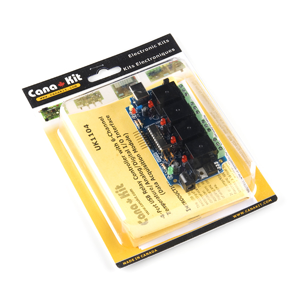
USB Relay Controller with 6-Channel I/O
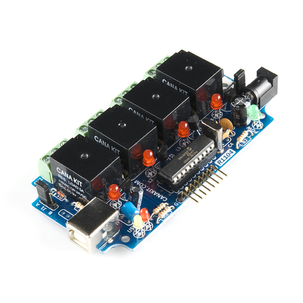
This USB Relay Controller / Data Acquisition Module, from Cana Kit, allows computer controlled switching of external devices as well as full bi-directional communication with the external world (ideal for Data Acquisition applications) using the USB port of your computer. The controller is very flexible and can be used in many custom applications including weather stations as well as temperature monitoring, logging and control as it can be easily connected to temperature and other types of sensors.
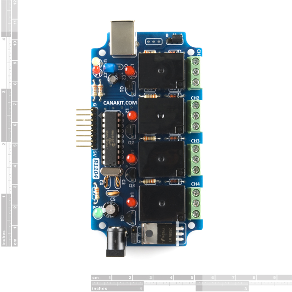
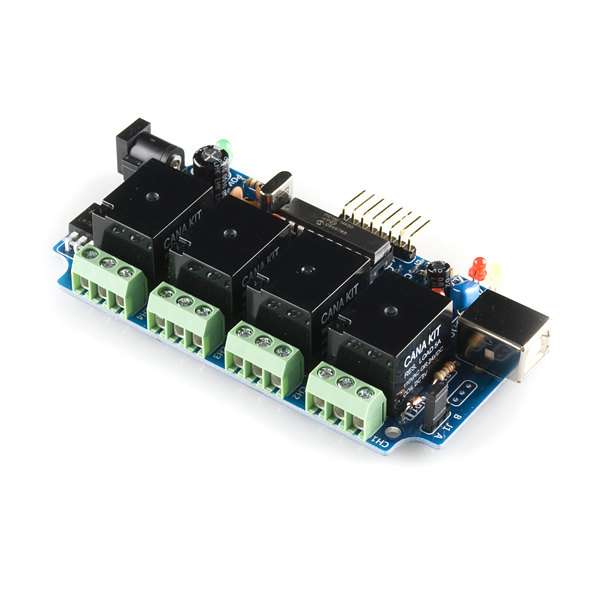
The controller provides four relay outputs with a current rating of 5A each. In addition, it provides a 6-channel Input/Output interface, with each channel individually configurable as Digital Input, Digital Output, Analog Input (10-bit Resolution), or Temperature Sensor (Dallas/Maxim 1-Wire Series).
In Digital Input/Output modes, each channel can support a TTL compatible or ST (Schmitt Trigger) input (depending on the channel) or a 5V output signal.
In Analog Input mode, each channel can convert a voltage of between 0 to 5V (or higher voltage using a voltage-divider) into a 10-bit digital representation.
Finally, in Temperature Sensor mode, each channel can be connected to a Maxim/Dallas 1-Wire Digital Temperature Sensor device (sold separately) such as the DS1822, DS18S20, DS18B20 or DS1821 and provides temperature readings in both Degree Celsius or Degree Fahrenheit.
It is compatible with both Windows and Apple OS X, as well as various Linux flavors and appears as a USB CDC (Communications Device Class) device which creates a Virtual Serial (COM) port allowing easy communication with the board through any programming language that supports serial communications (VB, VB.NET, C#, C, C++, Perl, Java, etc). A complete set of easy to use commands are available for complete control of all relays, I/O channels and sensors.
- Number of Relays: 4
- Number of I/O Channels: 6
- Relay Rating: 5A 110V AC / 24V DC (Resistive Loads)
- I/O Channels individually configurable as Digital Input/Output, Analog Input or Temperature Sensor
- A/D Converter Resolution: 10-bit
- Compatible with Maxim/Dallas 1-Wire Temperature Sensors
USB Relay Controller with 6-Channel I/O Product Help and Resources
Core Skill: DIY
Whether it's for assembling a kit, hacking an enclosure, or creating your own parts; the DIY skill is all about knowing how to use tools and the techniques associated with them.
Skill Level: Noob - Basic assembly is required. You may need to provide your own basic tools like a screwdriver, hammer or scissors. Power tools or custom parts are not required. Instructions will be included and easy to follow. Sewing may be required, but only with included patterns.
See all skill levels
Core Skill: Programming
If a board needs code or communicates somehow, you're going to need to know how to program or interface with it. The programming skill is all about communication and code.
Skill Level: Rookie - You will need a better fundamental understand of what code is, and how it works. You will be using beginner-level software and development tools like Arduino. You will be dealing directly with code, but numerous examples and libraries are available. Sensors or shields will communicate with serial or TTL.
See all skill levels
Core Skill: Electrical Prototyping
If it requires power, you need to know how much, what all the pins do, and how to hook it up. You may need to reference datasheets, schematics, and know the ins and outs of electronics.
Skill Level: Rookie - You may be required to know a bit more about the component, such as orientation, or how to hook it up, in addition to power requirements. You will need to understand polarized components.
See all skill levels
Comments
Looking for answers to technical questions?
We welcome your comments and suggestions below. However, if you are looking for solutions to technical questions please see our Technical Assistance page.
Customer Reviews
3.3 out of 5
Based on 3 ratings:
2 of 2 found this helpful:
Works as advertise but need more OS documentation
The controller works exactly as advertise but there's little or no documentation on how it works under Linux. A little more documentation and examples would sure cut your development time.
Holds what it promises.
Easy to handle with Linux and it is stable reading with good accuracy on the analog ports.I like direct temperature reading from the 1-Wire Digital Temperature Sensor. However, would like an option even with optoisolated semiconductor relays.
Not ready for prime time...
First tried it out with a VISA test panel (like a terminal emulator) in NI MAX. Could never get it to respond with the : (hex 3A) prompt the way the instructions say it should. I could turn individual relays and port bits on/off as outputs, but could never read anything sensible back from the unit like relay or bit status. Kept getting part of a command string back, like it was stuck in a buffer somewhere. Tried observing I/O as both ascii and hex, in case MAX was sending some whitespace character not visible in ascii.
Since all I really wanted was relay outputs, went ahead an placed it in our system, which has 2 chillers and a vacuum gauge, all using serial comms. They all work fine, but when written to in a loop with poll times between 1-5 seconds, this unit would eventually fail, throw a VISA error, and stops responding. Maybe we just got a bad one, don't know.
A couple other beefs: The relays and bits can't be written using a single byte. While there are ALL ON, ALL OFF commands, if one wants each relay set a different way, you have to loop and write to them all individually.
When I went to mount the board on standoffs, found that that there is very little clearance around the holes. Even a 3/16" standoff has to be carefully placed to avoid touching a live pad.
i have made almost same thing , with 8 digital I/O, PWM output and 3 Analog inputs. but with USB HID protocol , opensource Firmware and Qt 5 application.
http://www.circuitvalley.com/2015/10/usb-io-board-linux-mac-osx-windows-cross-platform-pwm-analog-qt5-qt-creator.html
Having problems using this with Win7 64-bit. Seems to drop characters. See forum topic
Same thing happening for me. After spending hours coding around the dropped characters, I've deemed it unusable and will proceed to purchasing the same board that dlotton recommended on that forum.
If you haven't read the forum: CanaKit recognizes the dropped character problem, and intends to do nothing about it.
I really want to use this product using the Linux Mint operating system but I really need help writing a driver. Linux does not recognise this device when plugged into a usb port but I can detect it using the terminal command sudo lsusb. Can anyone give me a little help? Thanks.
It's a bit pricier, but I've found the KTA-225 made by Ocean Controls significantly better (read: actually usable) than this CanaKit Board. Sparkfun stocks the brother to this board, KTA-223 (less analog inputs, but has opto-isolated digital inputs).
Pros: It doesn't drop characters, can be programmed as an arduino, accepts arduino shields, you can poll for all of the analog input values at once, you can poll for all relay statuses at once, communication is faster, interface and support provided are much better (many examples, sample code, support for wifi and ethernet hookup).
As of 6/25/12, in the online manual for this device it specifies a 9VDC power source is needed. However, in the manual shipped with the device, it specifies a 12VDC power source.
According to Kana Kit, the 12v relays they use on this trigger fine with 9v as well, so either 9v or 12v can be applied. They are also working on updating their documentation.
Not sure why what you connect to the switch contacts of the relay should interfere with the usb opration, unless they stupidly connected the Common of the USB section of the pcb to one of teh switch contacts of the relays??? Gnerally a relay should provide decent isolation.
Terrible product!!! Do not buy!!! unless you want a temperamental POS that is...constantly hangs. not a robust USB device at all
Great board. I needed to operate small 12 Volt solenoids via the relays.
Sure enough, as documented regarding inductive loads, it interfered with the USB connection and caused it to drop.
Solved the problem by putting 100 MFd 25V caps across the relay contacts. Works perfectly now.
Nice, do you think that would also work for a 24V DC solenoid? The solenoid draws about 450mA.
I'm working to get this board working under OpenWRT using Lua. It is recognized fine with kmod_usb_acm by the way -- shows up as /dev/usb/acm/0. Was wondering if anybody knows just what the "ACT" led really means. Com Buffer full maybe? I can send it a command or two then it hangs, and that ACT led remains on. Nothing noted in the docs about it and no sample code out there on the manf site.
Is there a place to get OSX support for this device? <br />
<br />
I plugged it in, it was auto detected, auto took me to preferences-> network, and showed me a new modem device(CANA KIT UK1104). But, I can't find any info for the config. Should it get a phone number. Are there any terminal command examples? I don't see any of this information in the manuals.<br />
<br />
""A complete set of easy to use commands are available for complete control of all relays, I/O channels and sensors."" I guess I am looking for a little bit of guidance on how this is actually done.
These are the steps I used to get started (OSX 10.6):<br />
<br />
Plugin device via USB<br />
- Device may be auto detected as a modem (mine was)<br />
- No additional configuration required, select ok or show all and leave preferences.<br />
<br />
Connecting to device:<br />
To connect to the device without downloading additional software, enter the the OSX terminal application and enter:<br />
screen /dev/tty.<br />
Then press the tab key (not the return key)<br />
<br />
This should bring up a list of available connection options (listed as files). Mine was: usbmodem1a21<br />
Complete the connection command:<br />
screen /dev/tty.usbmodem1a21<br />
<br />
You may see a blank screen, press return and you should see a "::" prompt. Begin entering commands, for instance: REL1.ON<br />
<br />
A list of commands is in the manual
To exit the screen application, type: control-A, then control-.
To quit the screen app, type control-A then control backslash (last post ate the backslash)
Some USB devices don't like to work through hubs. This is one of them. Works fine when plugged in directly to a USB port on the computer, though.
Can I run 24V 0.5A through the relay circuit? The manual seems to limit it to 9V, but the features above state 24V. I'd also like to use that 24V to drive a moderate torque motor, is the 5A rating enough to compensate for the inductive load?
n/m about the 24v through the relay... misread the manual. Still hope to find the answer to the inductive vs resistive load.
name might be misleading, i first thought "6 relay control"