- Home
- Product Categories
- GPS
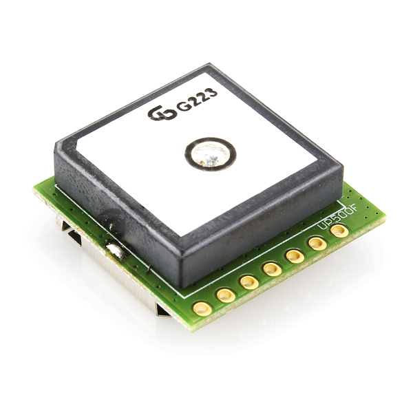
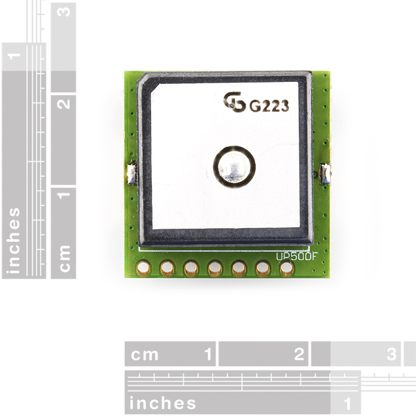
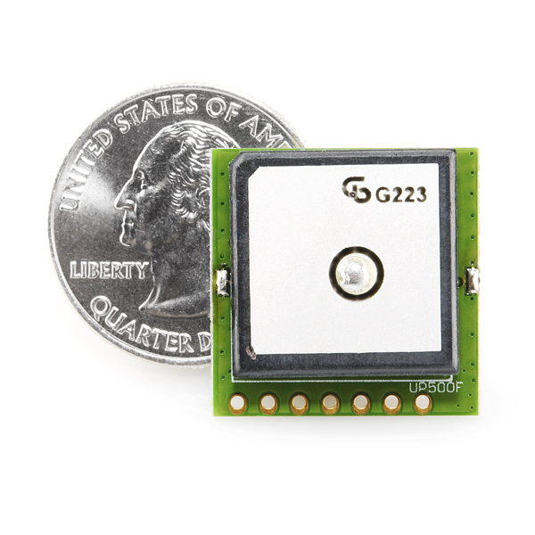
- 65 Channel SUP500F 10Hz GPS Receiver with Smart Antenna

65 Channel SUP500F 10Hz GPS Receiver with Smart Antenna
Replacement:GPS-08975. We are no longer carrying the SUP-500 due to poor quality control. We are suggesting the LS20031 as a substitute module. This page is for reference only.
The SUP500F is a compact, all-in-one GPS module great for projects where fast and easy system integration is required. The receiver’s -161dBm tracking sensitivity allows continuous position coverage in nearly all application environments.
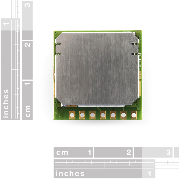
The SUP500F features various update rates up to 10Hz, and operates on an input voltage of 3.0-5.5VDC. The receiver comes in a rather small 22x22mm package, and all of the power and interface pins are *through-hole *(0.1" pitch), so it's very easy to physically connect to. The module outputs the standard NMEA-0183 sentences at a default rate of 9600bps.
Which GPS module is best for you? Check out our GPS buying guide!
**Note: **Although this unit is capable of 10Hz update rates, this should only be used in the most ideal of conditions. The fastest update rate should only be used in higher speed and open sky conditions.
- 65 Channel GPS L1 C/A Code
- Perform 8 million time-frequency hypothesis testing per second
- Open sky hot start 1 sec
- Open sky cold start 29 sec
- Signal detection better than -161dBm
- Multipath detection and suppression
- Accuracy 2.5m CEP
- Maximum update rate 10Hz
- Tracking current ~33mA* 0.87 x 0.87" (22 x 22mm)
- Weight: 9g
- Datasheet
- [GPS Viewer Software](http://www.sparkfun.com/datasheets/GPS/GPS Viewer_1124.zip)
- Venus634FLPx Datasheet
- Binary Command Set
- Firmware Update
Comments
Looking for answers to technical questions?
We welcome your comments and suggestions below. However, if you are looking for solutions to technical questions please see our Technical Assistance page.
Customer Reviews
No reviews yet.
No, there is something wrong - it will retain location and time for a minute or two, but not much longer, then it has to do the cold start.
Turned out that one of my soldering connections wasn't up to the job.
The battery is plated with something that doesn't solder well, and with the vibration from my motorcycle, it came loose. With some infrequent trips (at most 20 minutes per day) it remembered the AGPS, time and location for 5 days so far.
For an aside, this might be good to replace one of those Dallas RTC clock chips since it will retain the data with a similar backup and sends things out in serial format.
Now if only sparkfun had a WWV 60khz atomic clock kit...
Can we get a schematic for the SUP500F or is it just breaking out the Venus and adding a chip antenna?
2 weeks before AVC and you do this to me Sparkfun?!
:) ! Sorry HP. Don't change now! I'm still using my Locosys module from last year.
im trying to find a reason i'd need 65 channels, when theres only 58 gps satellites and you cant possibly see more than 1/3 to 1/2 of them at once... love the through-hole connection though!
That just gives us a reason to put more up there!
lol, true begins building a personal GPS array
The reason for 65 channels is the initial cold-start search when it has no idea where any satellite might be (or its doppler shift, etc.). There may only be a dozen needles ever visible, but they are scattered in a haystack with a thousand slots. If you have AGPS (and keep it updated) it is far less necessary (at least if it knows the time and lat/lon) so it has a good idea where the visible satellites are, more or less.
Those channels are also for WAAS.
Worst GPS Ever
I'm a bit sorry to see this dropped from the catalog, although I understand that many users have been having trouble. I bought one a few weeks ago and it's working fine now, although I had a couple of hurdles to get over. I have it mounted on an SD shield with an Arduino UNO.
One hurdle was that the serial output of the device cannot be directly input to the RX port of the UNO. The RX pin is pulled high by the USB interface and the drive of the SUP500F is not sufficient to overcome this. I put a TTL chip between the GPS and the RX port and that worked. The second issue only partially understood by me. I have the PPS output connected to pin 2 for use as an interrupt and also connected to a TTL latch. The GPS does not power up properly in this configuration without modification. If the TTL chip is pulled out of the circuit, everything powers up find. If the PPS line is wired to ground when the board is powered, everything works. I don't understand this, but I put a resistor and capacitor between the PPS line and ground and thing power up just fine. Somehow putting a load on the PPS line for a short time after power up makes things work.
If someone has one of these and is still having trouble, I'd recommend powering the device with the output pins unloaded to see if data is there when the output pins are then connected for monitoring. Some users said that they did not get a GPS fix, but I didn't see (or overlooked) any observations of what the NMEA output is during this time. When the device works, NMEA output is there instantly. If there is no serial output, then the device did not power up correctly and no amount of waiting will help. The PPS only appears after a fix is achieved but the serial output data is there righ away.
I hope that these comments help anyone who already owns one of these and is still having trouble.
Thanks for the tips.
I have not had the reliability I expect from a GPS module, though it is my first so I have none to compare with. Consequently, I have ordered another model from SparkFun and will see what performance it has. The problem I was facing was simply getting a lock. I have a 3V cell battery connected to keep all the memory data so I expect a lock within 1 minute at any time. However, this is not the case, I stuck it outside on the sidewalk for 15 minutes one day without getting a lock. Then on another day I'll get it in 2 minutes. It has been very inconsistent. I live in Vancouver, BC, Canada and it's around 0 celsius temp right now and I'm not sure if this is influencing the response. I noticed that if the module is powered by 5V instead of 3.3V, it seems to get a lock faster but I haven't done a true experiment to justify this. I have a XBee running about 2" away on the board, could this interfer? How important is a ground plane on the PCB? I believe I have had up to 9 satelites tracking but could there be a link between my northern location, the temperature, and the time of year that could influence locking?
Do you observe any NMEA output while you are waiting for lock? Or is the unit quiet? There may be tremendous unit-to-unit variability, but I've had no trouble getting lock in a short time within my house. However, I have had situations in which I powered the device while no output pins are loaded, then connected up some peripherals, and the device continues to work. If I don't touch any connections, but pull power and reapply it, the device would not start up. When I found a good loading of the output, I could power up and down without trouble. In every case, I had good NMEA right off the bat, or never.
My application requires the 1 PPS output, so that rules out some of the other devices Sparkfun sells, like the Locosys GPS. I'm using this GPS to support time and frequency work and don't even use the position.
How often do you pray, and to how many various gods?
But seriously, they can be temperamental at times. Also, batteries really hate the cold, so that could be a factor.
Thanks, well I look forward to summer and hopefully then it'll be more reliable!
How bout altitude? How high can it go? >>>18km?
It says it can, although kind of weirdly said. they say the COCOM limit is AND, although the footnote says its OR..? Weird. If it's AND i'll buy it, i promise.
Also, in the GPS guide you state something about missing a battery. But, there is a pin for VBAT!
I recently bought this receiver and have had trouble with it. I have not been able to get anything out of it. I am using an Arduino Duemilanove and connected power and ground of the receiver to the AD and connected pin 2 to Rx of the Arduino. I tried following the LS20031 Assembly Guide at:<br />
http://www.sparkfun.com/tutorials/176 <br />
<br />
but still had no luck. <br />
<br />
Any help please??<br />
Seems to work well, though not having much luck under anything but a clear sky. I used a MAX232 to do the RS-232 to TTL level conversion, and a voltage divider to get the output of the MAX232 down to the 3V needed for the module (I tried it briefly without the voltage divider and it seemed ok).<br />
<br />
Here's a quick writeup.
Doh... Found the button in the SkyTraq 0.4.503 software. The one at the bottom in the middle that says "Download". Who would have thought?
Stopped the GPS just in case. Uploaded prom.bin at 115200 baud, took longer to flash than to upload. Acts like a different GPS now. TTFF seems much faster. May store
last postion in FLASH on power down? I will try more different power up locations and see. THX Ken
How do you upload the firmware to the part? My GPS says 1.4.40, the update indicates 1.4.94. Is there any benifit to uploading the new firmware?
Seems to work well. A little slow to first fix from cold start. Altitude very slow to settle (compared to other units), MAP330, Garmin something, Magellen car model.
Linked configuration software works great. Change in SRAM if you are chicken, commit to FLASH after it works. I got the PPS at 4 second rate before I tied the backup power pin to 3.3V and the mode with a pullup. THX Ken
When I provide this module with 5V, the 1PPS pin pulses every 4.1s, forever.
The module has a good view of the sky, so it should acquire synchronization. This is the first time I switch this module on.
Has anyone experienced the same thing?
Same here -- a 4ms positive pulse, every 4.1 seconds or so (hard to tell exactly with this old scope). It doesn't respond to the configuration program anymore (although it did before). Maybe it's gotten itself into some sort of no-output mode? If I figure out how to wake it back up again, I'll post here. In the meantime, if anyone has any ideas, please post!
Also curious if there's any prediction for when this will be coming in?
any idea when these will be back in stock? I really need one soon for a science competition experiment.
Can we mount this GPS module sideways? Will the sensitivity get affected if we have the patch antenna facing sideways?
Help needed
Hello,
I connected this GPS module to Arduino Mega as following
GPS TX > AM RX1
GPS RX > AM TX1
GPS GND > AM GND
GPS VDD > AM +5
GPS BAT > AM +5
And uploaded the following sketch
void setup(){
Serial.begin(9600);
Serial1.begin(9600);
}
void loop(){
if (Serial1.available()){
int inByte=Serial1.read();
Serial.print(inByte,BYTE);
}
if (Serial.available()){
int inByte=Serial.read();
Serial1.print(inByte,BYTE);
}
}
It was working perfectly when I use Arduino serial port monitor and also I was able to read and write to the module perfectly using SkyTraq 0.4.603 software. Then through SkyTraq software I set ?Configure Position update rate? to ?10Hz ? and the module started to send fast unreadable characters and I lost control of the module.
I tried to change the sketch to use 115200 baud it did not help, I disconnected the module for more than 2 hours then reconnected it but it remains on the same settings and when I try to control it using SkyTraq software, it give error that module is not responding. Anyone can help me on this?
Please contact techsupport@sparkfun.com directly. Thanks!
I tried the QStarz 818XT 10Hz - the driver is wrong on the page, it does do AGPS but not SBAS (WAAS) at 10Hz. But it uses the MTK with 66 channels, so might lock in faster v.s. this.
If this module has the Venus chipset, it only has 12 channels, and can scan either 2 or 4 channels, but I've been using it with AGPS, SBAS, all at 10Hz, and it works as well if not better, though it might be a little less sensitive. That may just be the antenna.
One other thing - the Venus datasheet talks about adding a series and pullup resistor to the comm lines - are these in the module, or do they have to be added externally?
I am wondering about WAAS, too. The Sparkfun tracking comparison shows this one as having inferior accuracy. That may be because WAAS wasn't enabled.
WAAS works but doesn't improve things much - same as the SkyTraq.
I'm having some problems with the battery backup - AGPS stays, but not the lat/lon or clock, but I might need to redo a few solder joints - motorcycles are hard on connections :).
I've had no "open sky" problems when it had a proper battery backup, and already locked it. I could pull main power for a half hour and get an instant restart.
There are/were more severe problems - it can take several minutes (15+) without a really good open sky from a cold start - where it doesn't know the lat/lon/time since it can't use the AGPS and there doesn't seem to be a way to hint it - losing battery power loses location and time. Even with an open sky without AGPS the cold start can be a few minutes.
Performance was less than the SkyTraq breakout, but this might just be that the antenna is part of the module, so everything is close together (closer to my bluetooth module) and if I simply ran 4 wires (modular phone cable?) to make it more like a remote "puck", it would be better. The skytraq antenna is bigger and there is the active version. I'm going to try the helical on the SkyTraq.
Has anyone used the SUP500F with WAAS enabled? If so, how is the accuracy? Did it improve much with WAAS on?
I am considering using 2 of these modules and taking the differential position for heading measurement, and I wonder if this is reasonably likely to work or going to have huge amounts of noise.
Great. So where can i locate that sparkfun library?
http://www.opencircuits.com/SFE_Footprint_Library_Eagle
I love this gps module. Works nicely with my arduino projects. But are there any eagle library file for this item? Would be nice to use with my schematics and pcb design.
Vegard - Do you have a schematic of how you physically connect this GPS module to your Arduino? Looking to get it working as soon as I get mine in the mail.
It's in the EAGLE library we're using at SparkFun, so if it's not already in the released version it should be soon.
May I connect the shield dummy pads to ground?
Which "shield dummy pins" are you referring to?
In datasheet page 6 are refered as pin 7 and 8 SMD pads, and marked as NC no connect, but if they are connected to ground within the module, EMC should be improved connecting them to application PCB ground.
Good module, Today arrived mine, locked in 2-3 min inside lab, and yes, shield is connected to gnd, will test later in PCB.
Well I got this GPS working with an Arduino, thanks to the great support given my Mike and the SparkFun tech support! SOrry I left a bad comment before. The problem with interfacing this chip with an arduino is that the arduino serial lines read 5V serial data, and the GPS chip only output at about 2.8 volts, not quite high enough for the arduino to pick up. You have to boost the voltage on this serial connection and then it works!
Would this work with a 3v3 arduino unit without needing to correct voltage? I guess the 2v8 reported should be enough...
S/
I haven't had a chance to hook one up to a 3.3V Arduino, but it talked to a 3.3V FTDI board just fine.
I am Trying to set this up with an arduino, with the just tx GPS pin connected to the rx arduino pin, the power pins connected to 5v and pin 5 to 5V. i am just setting it up to Serial.Read() from the arduino @ 9600 bps, and I get nothing? Sparkfun Tech support stopped replying to my emails this week. Any ideas? I am beginning to think this is just a conversation piece.
I am a bit disappointed...:
This is the first time I am using GPS, but results seem to be pretty bad. The SUP 500F is configured for 10Hz GPGGA output @38200 baud. Hor. dilution of precision was around 1.2, around 7 satellites were tracked (free view to the sky, good weather etc.). And this is the position (I stayed 1 min on the same spot):
http://www.villalachouette.de/william/krims/tricopter/websitepics/sup500_gps.jpg
Here, I was driving with my car (NOT through trees and houses, I promise...):
http://www.villalachouette.de/william/krims/tricopter/websitepics/sup500_gps2.jpg
Is this all I can expect from GPS? I want to use it for position-hold for my tricopter design (http://shrediquette.blogspot.com), but it won't work the way it is now...
That GPS is not THAT accurate is a fact. The reason it works well in cars is because it is constrained to the roads it drives on, and has some smart kalman filtering.
I am having problems getting this unit to talk.
I am using a RS232 Shifter SMD.
Rx from SMD to Tx on gps
Tx from SMD to Rx on gps
VDD is at 5V
Vcc on the SMD is 3.28V for the TTL level.
pin 5 is connected to the 5V
I am using the Sky Traq software 0.4.603
In the software it sayes it is connected but i an not getting any data from it.
Do i need pins 6 and 7 connected to any thing?
No, those pins don't need to be connected to anything. Are you using the unit inside or outside?
If you continue having issues with it, you would be best to email techsupport@sparkfun.com
I have just received a unit and got it communicating with the GPS Viewer software. (Using FTDI cable - 5V). Power to the module is 5V and Advanced acusition is enabled.
Set the update frequency to 4Hz and baud rate to 115200.
I have sucessfully updated the AGPS also.
The problem I have not is with the cold start. If I point the receiver outside my window, which has a 80 degree view of the sky, I never got a lock (tried all the Cold, Warm and Hot start). I actually have to go out in the open, have a very clear view of the sky, and then wait 30+ secs, then I get a lock.
For my phone with built in GPS module, I can even get a lock even if I am standing inside the window.
How do I get it to start when it has less the a "clear-sky view"?
Email us directly at techsupport@sparkfun.com and we can try and sort it out.
I'm having a problem with this module.
Configuration is :
FTDI 3.3v cable
cable TXD (orange) connected to module Pin 1 RXD
cable RXD (yellow) connected to module Pin 2 TXD
cable GND (black) connected to module Pin 3 GND
cable VCC (Red) connected to module Pint4 VDD
no other connections:
using tera term 9600 N81 - I don't see any data
using GPS View_0422-1 - I don't see any data
Any Ideas ?
Thank You
You should also have,
FTDI 3.3v cable's VCC also connected to module Pin 5 VBAT, before data could start coming in.
This is a relatively general question, but what is the best way to use this with a 5v arduino? Sparkfun's logic level converter is sold out. My initial thought was just to use a voltage divider from the arduino to the gps, then hope that the arduino would recognize the 3.3v coming the other way. Any insight would be great.
Thanks
If all you want to do is receive the data you can leave the RX on the GPS module unconnected--I've had this successfully operating with my Arduino.
A resistor voltage divider would probably be the easiest way to handle the Arduino TX to GPS RX level conversion.
I have a display in my car that displays various engine values and most important the speed at 2 Hz .
I read only the RMC @ 19.2kbps @ 2 Hz .
The SUP500F ,
Very fast Time To First Fix about 30sec , but occasionally does not find satellites when standing still . ( This problem did not occur in neither the LS20031 or the FV-M8 )
Consistent readings accelerating and best tracking of slowing down fast .
Occasionally ( During the first minutes after power up ) displays speeds way off . ( This morning it indicated i was driving at 1052 km/h ... in 15-20s returned to normal )
The FV-M8 ,
TTFF about 90s .
Good and consistent speed readings . Except with fast temperature changes .
Another problem with this module is the forgetting of settings even when there is a battery connected .
I have had this GPS installed for 4 months and i have had to re-set the settings at least 15 times now .
( I have observed the GPS losing settings just after power up and about a minute after power up )
The LS20031 ,
My opinion : best GPS of the three on the long run ...
TTFF 30-90s .
Good following of accelerations , not as good on slowing down .
Internal battery , almost as good as Flash .
I'm losing my nerve ...
How do i change the baudrate to 19.2kbps , and the output string to only RMC @ 2 Hz ???
Please help !
I have tried every GPS program i can find ... even MiniGPS failed , it reads correctly but does not change any setting ...
Checkout the configuration software. It is only for windows but I'm able to configure update rate, baud rate, WAAS, and AGPS settings.
The unit does have WAAS, but its off by default.
I think that most china maker can write 100 channels. but really not any words about A-GPS (and other). Now i decide design PCB with U-blox G100/200 module and NEO-5 GPS adapter. With ALM-1712 GPS amplifier it's really work with only 1/8 open sky and with A-GPS from U-blox works w/o lost GPS satellite signal. I think desing pcb with arduino compatible pins and also adopt a leaflab maple platform (STM32) - projects on their site has some principal error but not a fatal. GSM/GPS with U-blox design as standard arduino's sizez board and now it complete. Currently work with correct STM32 arduino board. All news and files available at http://akb77.com/g (2-3 days to complete)
I assume this unit has no WAAS capability (not mentioned in the spec sheet.) If so, it seems the LS20031 GPS 5Hz Receiver might be a better choice, other than for the slower update rate.
This is not a surface mount component and yet no mounting holes. Are users expected to let it hang on those wires?
From the manual: The SUP500F can be mounted on the application PCB using standard 2.54mm pitch 1x6 pin header. Two dummy soldering pads on the RF shield are used to fix the module to the application PCB.
I'm pretty confident with a 1x6 header. They're pretty hard to bend with such a short moment arm. If you really need it (for crashing vehicles like I do) a little hot glue or double stick tape does wonders.
http://www.cyberitech.com/gps.htm
Of course there aren't any matching part numbers at that site, - I'm guessing this is the Uranus-622.
But even the data from those doesn't say ANYTHING about how to change the baud rate, nor are there utilities or much more than the datasheet here.
You can't do 10Hz NMEA at 9600 baud.
Moreover, the Venus 624 (if you get the right firmware update) does AGPS and WAAS, so you get instant lock and better accuracy with the 10Hz.
The documentation is a bit sparse... No mention of how to set the baud rate, what commands is responds to (send to unit), or even who the manufacturer is.
use the software, it also says in the manual but in the binary command set. In the software you have to go to binary, up the top where file and stuff is, then choose your settings from that menu