- Home
- Product Categories
- Development Tools
- GPS Shield

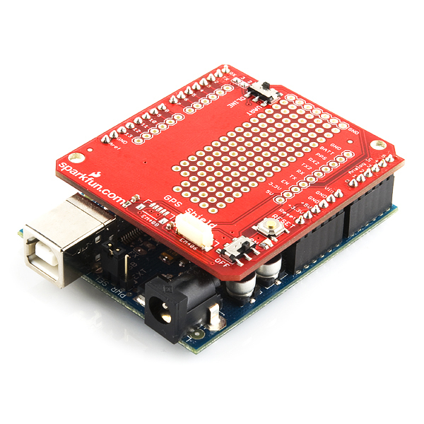
GPS Shield
Replacement:GPS-10102. We've added a header for the SUP500 GPS module. This page is for reference only.
Adding GPS to your Arduino has never been easier. The multiple GPS receivers attach easily to the shield, and with the example sketch, you will be able to locate your exact position within a few meters. Here's where we are. GPS also gives you amazingly accurate time! A GPS quickstart guide is available for this product.
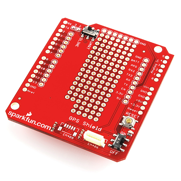
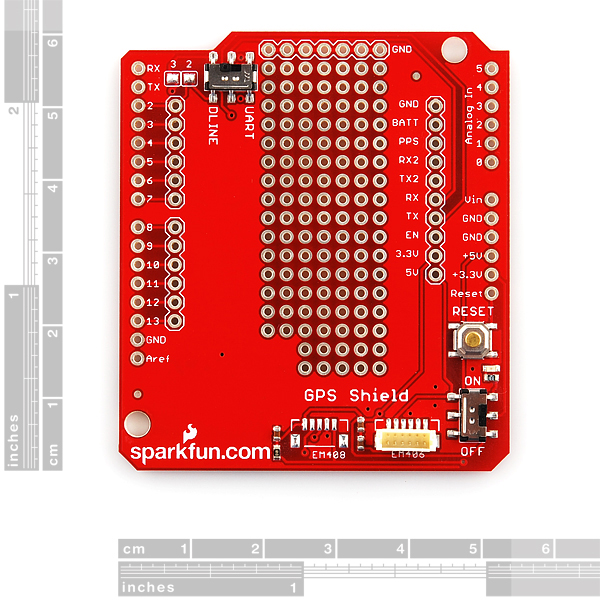
With the GPS Shield you can add GPS functionality to your Arduino. A connector for the popular EM-406 GPS receiver is populated on the board, and footprints for EM-408 and EB-85A/FV-M8 connectors are also made available (connectors are not soldered on or included and can be found below in the related items). The regular GPS pins (RX, TX, PPS, etc.) are also broken out to a 10-pin 0.1" pitch header, and a small protoyping area is also provided.
The DLINE/UART switch switches the GPS module's input/output between Arduino's standard TX/RX pins or any digital pins on the Arduino (default setting uses pins 3 and 2 connected to TX and RX, respectively). The regular GPS pins (RX, TX, PPS, etc.) are broken out to a 10-pin 0.1" pitch header, and a small protoyping area is also provided. An ON/OFF switch is included which controls power to the GPS module. Additionally, the Arduino reset switch is also brought out.
**Note: **The DLINE/UART switch must be set to DLINE in order to upload code through the Arduino IDE.
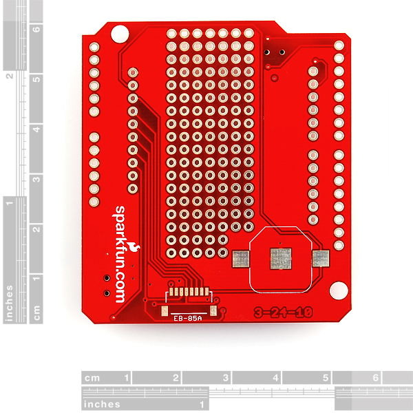
The shield also includes the footprint for a 12mm coin cell battery holder to provide battery backup to the optional EB-85A gps module.
**Note: **GPS modules are not included with the GPS Shield, and only the EM-406 connector is populated. Headers are also not installed, we recommend the 6 and 8-pin stackable headers.
**Replaces: **GPS-09487
- EM-406 connector populated
- EM-408 and EB-85A/FV-M8 connector footprints provided and connected for optional use
- Coin cell battery socket footprint provided and connected for optional battery backup of EB-85A GPS module
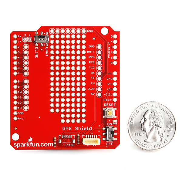
- Standard Arduino sized shield
- Prototyping area
- GPS serial and PPS signals broken out to a 0.1" header for additional device connections
- Arduino reset button
- DLINE/UART switch controls serial communications
- ON/OFF switch controls power to GPS module
GPS Shield Product Help and Resources
GPS Shield Hookup Guide
March 9, 2015
This tutorial shows how to get started with the SparkFun GPS Shield and read and parse NMEA data with a common GPS receiver.
Comments
Looking for answers to technical questions?
We welcome your comments and suggestions below. However, if you are looking for solutions to technical questions please see our Technical Assistance page.
Customer Reviews
No reviews yet.
Link to the example sketch is broken (404 not found)
Sorry about that, should be fixed now.
I've noticed that both of the latest shields now include the capability to re-route TX/RX to any digital line we want (without trace cutting).
Bonus props for providing a breakout header for all the signals.
Thank you so much for doing this, and I hope that all future shields will eventually give us this flexibility.
Thanks! We always like to hear when we've done good. It was feedback from customers such as yourself that made it better. Let us know if we can do more.
It appears (from the schematic and a continuity test) that the EM406 PPS is not connected to the PPS break-out. Why is that? and will that be fixed in a later revision of the shield? Thank you!
Hi, since I'm new to this, my question is quite simple...<br />
When you say I can re-route the TX/RX to any digital line, although the defaults in DLINE (2 and 3) is made by code correct? So I can #define RXPIN 3 to #define RXPIN 8 and #define TXPIN 2 to #define TXPIN 9, for example?<br />
<br />
Sorry about the "lame" question, but I'm planing to stack a couple of shields, and this is important. <br />
<br />
Thanks, and like 33Warlord already said let's hope in the future all the shields will give us this flexibility.
here is the link I used that required code change:
http://www.sparkfun.com/tutorial/GPSQuickStart/gps_parsing_v12ii.pde
kurg thanks for posting. I must have stumbled across and old link because I was having the same problem until I fixed the code...
No worries, what I should have said is, "if ONE fixes their code". The fix is simple to change the RX/TX in any software, not specifically provided by Sparkfun. For example, when I instantiate a NewSoftSerial port, the difference between the two revisions of the board would be:
NewSoftSerial nss(3, 2); //older rev
NewSoftSerial nss(2, 3); //newer rev
A note about the physical change would probably save others some time.
If I'm not mistaken, this part is not a drop in replacement for the previous revison:
http://www.sparkfun.com/commerce/product_info.php?products_id=9487
In the new rev, D2 is D_RX, and D3 is D_TX whereas with the previous rev, D2 is D_TX and D3 is D_RX.
This isn't a problem if you correct your code, but if you try to use the two parts interchangeably BEWARE! Can I get back 2 hour of my life?
If we could refund time, we would be much much bigger than we are. Sorry about that, we'll get the code changed.