- Home
- RFM22-S2 RF Transceiver Breakout Board

RFM22-S2 RF Transceiver Breakout Board
Replacement:WRL-10154. The new breakout board uses the RFM22B module, which is the newer revision. This page is for reference only.
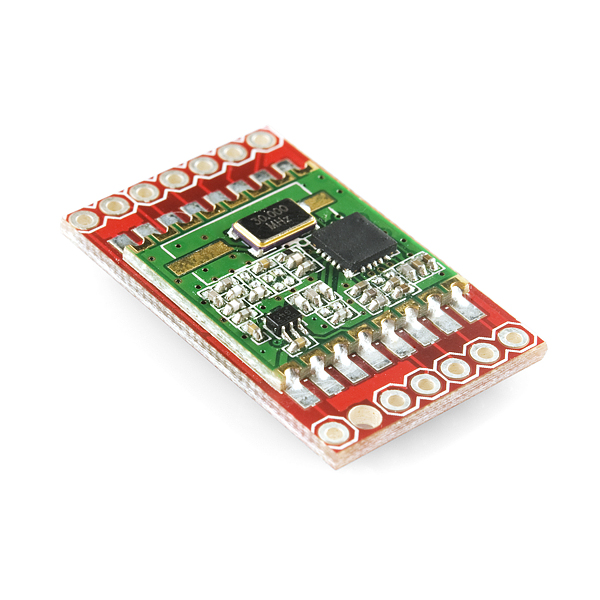
Here is the breakout board for the RFM22 which gives you access to the pins. The RFM22 is a low-cost ISM (industrial, scientific, and medical) FSK (frequency-shift keying) transceiver module which offers communication at 434MHz and adjustable output power of up to +17 dBm. The wide operating voltage range of 1.8–3.6 V and low current consumption makes the RFM22 an ideal solution for battery powered applications.
Communication with the RFM22 is achieved via a standard 4-wire SPI interface. Three configurable general purpose I/Os are also available, the use of which can be tailored towards the needs of your project. A host of other features are also available including an 8-bit ADC, temperature sensor, RX and TX FIFOs, and low-battery detection. See the datasheet below for a complete description of every register and command.
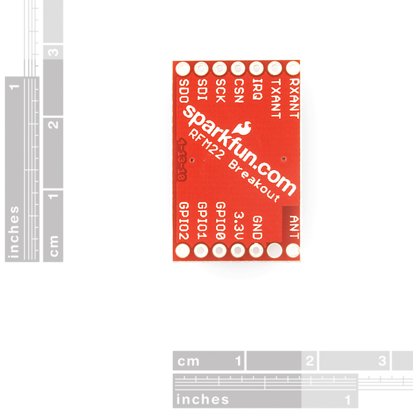
In our testing, a 17cm wire attached to the 'ANT' pin worked just fine. A hole is drilled next to the 'ANT' pin for strain relief.
- Frequency Range = 434 MHz
- Sensitivity = -118 dBm
- +17 dBm Max Output Power (Configurable)
- Low Power Consumption
- Data Rate = 1 to 128 kbps
- Power Supply = 1.8 to 3.6 V
- Ultra low power shutdown mode
- Digital RSSI
- Wake-on-radio
- Auto-frequency calibration (AFC)
- Configurable packet structure
- Preamble detector
- TX and RX 64 byte FIFOs
- Low battery detector
- Temperature sensor and 8-bit ADC
- -40 to +85 °C temperature range
- Integrated voltage regulators
- Frequency hopping capability
- FSK, GFSK, and OOK modulation
- Low BOM
- Power-on-reset (POR)
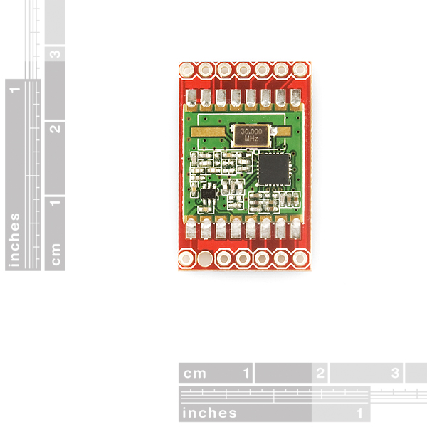
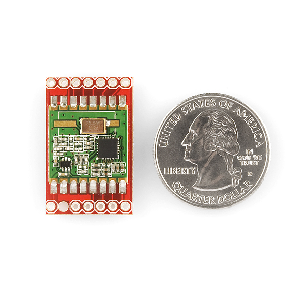
- 0.63x0.63in (16x16mm)
- Schematic (v12)
- Example Code (ATmega328)
- Datasheet
- Hope RF's RFM22 Product Page
Comments
Looking for answers to technical questions?
We welcome your comments and suggestions below. However, if you are looking for solutions to technical questions please see our Technical Assistance page.
Customer Reviews
No reviews yet.
Does anyone understand the "wake on Radio" function. I have looked on their data sheet and website and it is not clear. Appreciate any help
thanks
It isn't mentioned anywhere, so I would pretend it doesn't exist...
They may just be referring to the wake-up timer, which is pretty straightforward. You set a timer that will periodically wake up the radio (and an external microcontroller, if you want). You just set a register and away you go! I used it on the RFM12B I utilized in a previous project.
I'm doing a wiring diagram for a prototype with one of these things and its very confusing.
The markings on the PCB do not match the documentation for the pinouts, and the placement of the connections on the PCB does not correspond to the documentation either.
Practically, I'm trying to make sense of the pinout on the board as it it described at http://www.open.com.au/mikem/arduino/RF22/ :
I coundn't really get it working properly with the Example Code from the Documents section. On average I could receice about one out of ten packages correctly on average.
Now I am using the following code, which also has a much nicer API, and it works perfectly:
http://www.ulrichradig.de/home/uploads/File/RFM22_AVR/LSS.zip
The wiring in the example code contains errors: This
SCK | PB4 (D13)
SDI | PB2 (D11)
SDO | PB3 (D12)
should be corrected to this
SCK | PB5 (D13)
SDI | PB3 (D11)
SDO | PB4 (D12)
Holy moley!
$23 for this, while the RFM22-S2 by itself is $11?
Disappointing pricing, IMHO. Much better to just solder some solid 24 AWG wire to the bare unit and plug them directly into your breadboard. A bit more work but if you're going to make a final version of your project, you can make your footprint perfectly anyway.
Agreed. Maybe they lowered their price for the module and haven't yet done so for the BOB + module.
Doesn't make sense otherwise.
There aren't any additional smoothing caps, resistors, or trace antenna.
$12 for a 2mm to 0.1", single sided, under 1 sq inch BOB without headers doesn't sound like typical SparkFun pricing.
Can anyone comment on how these modules compare to the nordic modules in terms of range and programming complexity ?
Nice. Looks tiny too. I'll definitely be picking some of these guys up to play around with.
I know 900MHz is better for NLOS and foliage penetration. Would 434MHz work even better for such things? Gotta love putting electronics in the woods.
Most of the time, lower frequency = longer range.
What is the typical range that can be achieved with these modules?