- Home
- Product Categories
- GNSS Antennas
- GeoHelix GPS Antenna

GeoHelix GPS Antenna
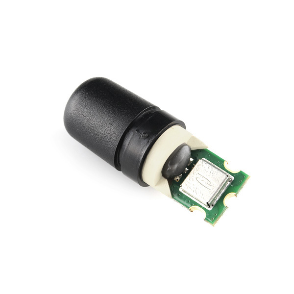
The GeoHelix antenna from Sarentel is a one of those really odd looking antennas. Block ceramic antennas have good gain, but really have to be facing up towards the sky to get a good signal. Helical antennas (and Sarantel seems to have the world wide patent on them) have slightly lower gain, but can get a signal in many more orientations - more like real world usage. Use this antenna if you're not sure how the GPS unit will be oriented toward the sky.
Based on the patented GeoHelix technology, the SL1204 integrates a high performance, optimized gain, low-noise amplifier with Sarantel's second generation GeoHelix antenna for receivers requiring an active input. The SL1204 provides typical 18dB gain and has been optimally designed to work best with the latest generation of GPS chipsets.
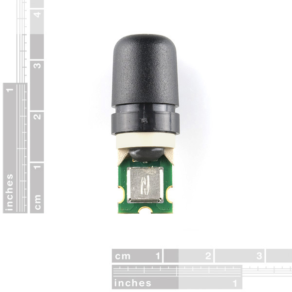
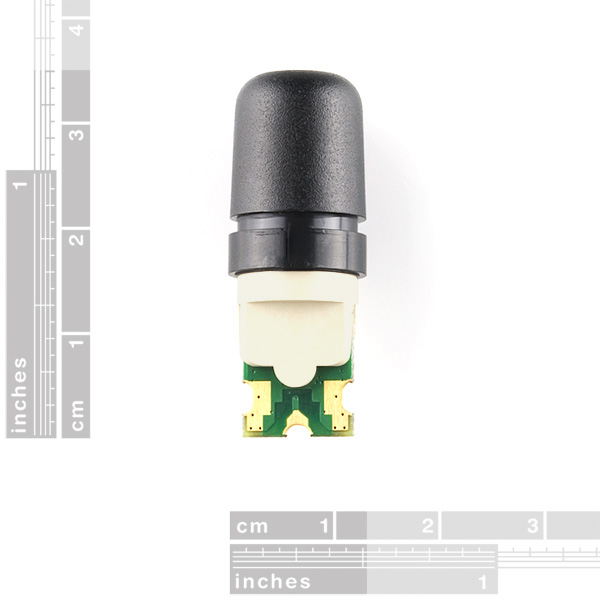
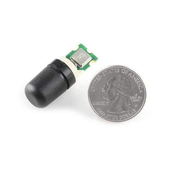
This unit comes as a bare module with a black plastic cap protecting the copper etched antenna underneath.
- Medium gain - 18dB typical
- Rejects conducted noise form application
- Wide cardioid beamwidth (>135° typical)
- Negligible detuning close to human body
- SMT compatible
- Low current consumption
- [Datasheet](http://www.sparkfun.com/datasheets/GPS/SL1204 Product Specification_v2_10_2009.pdf)
- [Mechanical integration guide](http://www.sparkfun.com/datasheets/GPS/Mechanical Integration of SL1206 and SL1204 Active Antennas.pdf)
- [Electrical integration guide](http://www.sparkfun.com/datasheets/GPS/SL1206_SL1204 Electrical_Guide_v10.pdf)
GeoHelix GPS Antenna Product Help and Resources
Core Skill: Soldering
This skill defines how difficult the soldering is on a particular product. It might be a couple simple solder joints, or require special reflow tools.
Skill Level: Competent - You will encounter surface mount components and basic SMD soldering techniques are required.
See all skill levels
Core Skill: Electrical Prototyping
If it requires power, you need to know how much, what all the pins do, and how to hook it up. You may need to reference datasheets, schematics, and know the ins and outs of electronics.
Skill Level: Competent - You will be required to reference a datasheet or schematic to know how to use a component. Your knowledge of a datasheet will only require basic features like power requirements, pinouts, or communications type. Also, you may need a power supply that?s greater than 12V or more than 1A worth of current.
See all skill levels
Comments
Looking for answers to technical questions?
We welcome your comments and suggestions below. However, if you are looking for solutions to technical questions please see our Technical Assistance page.
Customer Reviews
No reviews yet.
The former US distributer for Sarantel was Jim D Gray & Associates http://www.jdgagps.com/. When Sarantel went out of business, they bought as much stock as they could to support their customers. As of Jan 2015, they had a small amount of parts left and can build up equivalent antennas.
Works great with the Trimble Copernicus. Any idea when this will be back in stock?
I think they are not being manufactured anymore. They claim to have a limited supply but useless for volume projects.
http://www.richardsonrfpd.com/content/english/aboutus/Pages/Suppliers-Storefront.aspx?supplierId=1054
"Sarantel, Ltd has ceased operations. Their patented ceramic loaded helix antennas are not longer being manufactured. Richardson RFPD has a limited amount of inventory available. All product is for sale but the factory warranty implied in Sarantel data sheets is void. Please contact Richardson RFPD for additional information or alternative sources."
I really like these antennas and they always worked well inside for me. Is there a comparable antenna on the market?
Has anyone created an Eagle layout for this?
whats in the shielding there?
I'm very pleased with this antenna. It pairs very nicely with a u-blox LEA-6T with just the recommended 10 ohm resistor to allow the u-blox chip to power the antenna. The reception is good enough for it to work inside (for me!) which I've not achieved with other GPS setups I've played with.
Hi, did you use a 10ohm resistor or a 50ohm resistor? The electrical integration PDF mentions a 50ohm, but I'm wondering if the PDF had a typo, or maybe you did above? Thanks
The 50ohm resistances in electrical integration pdf aren't "real" resistors. They are 50ohm controlled micro strips, aka copper trace on pcb with specific width and separation to ground. There are free online calculators for calculating the proper dimensions.
be vary careful with this module; mine broke off 'internally' although i couldnt even see it.
Edit: You can also get these things without the amplifier (translates to a -5dB gain vs. +18dB), which will solder right to an SMA.
I looked at the PCB layouts, and it looks like with really careful soldering, you could get it to work.
Also, note that when Sparkfun is out of stock (which seems to be frequent) Jim's usually has them available: http://www.jimdgrayassoc.com/index.htm
And, they have one (Not Sarantel, but 'drop fit') for less than half the price:
http://www.jdgastore.com/index.php?act=viewProd&productId=16
Reading carefully it also requires power. I think the Venus BoBs are properly setup for this.
But as HansDR asked - can I just desolder the SMA and add this instead?
Any chance that Sparkfun could provide this with an SMA connector so that it could be connected to the Venus GPS breakout board?
Or, do you think that the solder pads are similar enough to the SMA connector's solder pads on the Venus GPS breakout board that it could be connected directly to that board?
I managed to get this to work with the venus board by desoldering the SMA connector. It was a bit tricky because the SMD coil on the board ended up so close to the center pad on the antenna, but it works! I was able to get a lock by placing the GPS inside near a window.