- Home
- Product Categories
- Components
- Serial/Analog Mux/Demux - 74HC4052

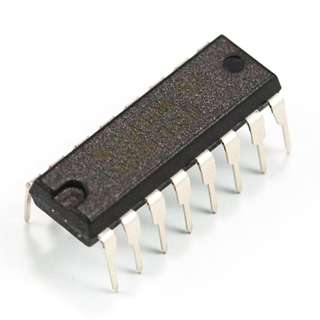
Serial/Analog Mux/Demux - 74HC4052
Replacement: None. We are no longer carrying this IC in our catalog. This page is for reference only.
If you've ever needed to hook multiple serial devices to one microcontroller, you understand how much of a problem it can be. The 74HC4052 analog mux/demux is one of those parts that, once we discovered it, was a life saver.
'Mux' means that the TX pin (X) can connect to any one of four outputs (X0, X1, X2, X3). So you can connect your micro's TX pin to four different listening devices such as the RX pins on a radio, GPS module (for configuration), data logger, serial LCD.
'Demux' means that the signal can go the other direction as well. So if you have both a radio and a GPS unit trying to talk to your microcontroller, the 74HC4052 allows you to switch between who you listen to. Realize that this does pose a problem. If you've got the A/B pins on the mux configured to listen to the GPS, you may miss incoming serial characters from the radio.
On top of all that, the 74HC4052 is analog as well. This means that you can pass analog values through the IC! So you can connect four analog sensors or signals to the X0/1/2/3 pins, and have them piped into one analog pin. This allows you to connect 8 analog devices using up 2 digital pins and 2 analog pins.
- Large VCC range: 2V to 10V
- Connect one TX source to four RX receivers
- Connect one RX receiver to four TX sources
- Works both with digital and analog signals
- Output drives up to 20mA
Comments
Looking for answers to technical questions?
We welcome your comments and suggestions below. However, if you are looking for solutions to technical questions please see our Technical Assistance page.
Customer Reviews
No reviews yet.
There are two control lines, A & B, plus an inhibit line (pin 6). It's essentially a two pole four throw switch. The two poles are X & Y, controlled like this, as long as INH is low:<br />
<br />
B A<br />
L L X connected to X0, Y connected to Y0<br />
L H X connected to X1, Y connected to Y1<br />
H L X connected to X2, Y connected to Y2<br />
H H X connected to X3, Y connected to Y3<br />
<br />
If INH is high, none is connected. Using the INH you can parallel chips to add more poles to your switch, just enable one chip at a time.<br />
<br />
By "connected", that's through a couple hundred ohms of a not very linear resistance. If you're switching audio signals, a large series resistance, like 10 kOhms or so, will swamp out the non-linearity and reduce distortion.<br />
<br />
Ray, this will work with digital signals, keeping in mind there are bandwidth restrictions.<br />
<br />
And like a switch, it's bi-directional. A signal on X could be routed to four different destinations, or four different signals could be selected to connect to X.<br />
<br />
One nice thing for switching audio signals is you can power it by +5 volts at Vcc and -5 volts at Vee, plus ground. Then the control signals are 0 & 5 volts, but the switch can handle a +/- 5 volts range.<br />
<br />
Hope this helps.
I really liked this chip! I current have this chip connected to a PIC18F4553, RFID reader, Xbee, and a serial LCD! I even wrote a short explanation of the chip on my blog http://coolcapengineer.wordpress.com/2013/01/04/electronics-serial-expansion-using-74hc4052/
what's the packaging on this?
I need something that will accept a single line of input, and which can output to one servo and an SN754410 H-Bridge chip. I can only use one line of serial input because I am using the wireless TX/RX 434MHz set sold here. Will this chip do that for me?
bought a few of these thinking they were 1 to 8's oh well guess i can make them that way lol
Can anyone provide a good example sketch or where to find one? I just need to connect a boatload of momentary pushbuttons and am at a loss.
Might wanna use an 8 to 3, 16 to 4, 32 to 5, or something to something encoder. For example if you connected 8 switches to an 8 to 3 line encoder, then when you pushed button #1, you would get the reading (using 3 digital pins): Pin 1: LOW Pin 2: LOW Pin 3: HIGH.
Okay, that explanation wasn't too good but maybe someone will correct me...
Thanks. I actually thought of doing the reverse of that (combination of 3 buttons controlling 8 outputs) after I already bought a few of these and realized I had overcomplicated things. Haha, oh well.
Hey I'm sure this is at least a slightly newbish question, but I'm really eager to learn about electronics. I have a set of PC speakers that I want 2 inputs to connect to (laptop and desktop) and want to make a switcher between the two.
Now If I didn't fail at reading the data sheet the input voltage can be anywhere form -5V to 5V, so would this component be suitable to handle line out audio for this switch, the other component that came to mind for this project are reed relays. Would either of these components be suitable? Or is there something magical that would be 42 times better then either of these?
You may also wish to check out the Fairchild Semiconductor FST3126MX Bus switch. There was an interesting article not too long ago that dealt with AV switching that used that chip. Sounds similar to what you want to do albeit more complicated(you might just want to take a few of the ideas they use).
Article
The only reason you wouldn't want to use this chip is that it only connects 1 input to 1 output. So you would need at least 2 if you want stereo audio. The bus switch connects multiple inputs to multiple outputs depending on the user selection. Apart from that audio is no more than a fast moving analouge signal.
Thank you for the advice and the article, exactly what I wanted to do (but with video as well)
I intend to drive standard RC controlled servos using two signals. I will have a select wire which will choose which signal the servo is to respond to. Can I use this chip do that selection? I have a feeling that it will work OK.
Thanks
Yeah that should work, but you should bear in mind that if a servo doesn't constantly get a signal from the controller it will not keep it's position. So when you switch to another servo the previous servo may begin to sag whatever it is holding(a swash plate or something judging from your name) it could be disastrous or it could just be inconvenient depending on what the servo is doing. I suppose if you switch quickly enough between the options the device might not notice but I'm not sure what calculations your controller is doing in the background that might slow it down and prevent a fast switch.
If you connect 8 analog devices, won't you need 2 analog pins to read and 4 digital pins to choose inputs?
Never mind.
For anyone who might wonder the answer, I think the reason it works is because the two digital pins can represent 4 different combinations, say {1,2,3,4}, and depending on which you select, you get analogs {1,2}, {3,4}, {5,6}, or {7,8}.
If I'm wrong, someone please correct me.
I'm about to order some of these for version 2 of my super led matrix sequencer.
I figured out that with 2 of these, and the 6 analog pins on a duemilanove, I can have 16 analog OR digital inputs! Good for my purposes, where I don't really know for sure what I will want to connect to the sequencer.
Gives me a lot of pins free!
These work well. I wish there was a generic analog logging board.
I couldn't find an explanation of how to change which input you are listening to, and which output to write to.
Has anyone used this successfully?
Should be compatible with simple digital signals also, right?