
Beginning Embedded Electronics - 4
Lecture 4 - UART and Serial Communication
Hello, Hello World
Sorry for the confusion. When these tutorials were written and photographed, we used the ATmega8. We now carry the newer ATmega168. You will find all ATmega168 information in the following pages, but the pictures will show an ATmega8.
The ATmega168 has tons of hardware built into it. Let's unleash the serial communication. Everyone has programmed the 'Hello World' program. You've got your micro breadboarded and running at 16MHz. You've got WinAVR up and running. We've already demonstrated LED control. Now it's time to pass some serial data back and forth.
I am not a huge coder. I just want my printf() statement to do what it is supposed to do. I don't use a hardware debugger, I debug by printf statements. Sure, there are limitations with this, but for 90% of the applications out there, debugging with printf statements works just fine.
First, a quick history of RS232. What is RS232? It's just a name for a standard that has propagated from generation to generation of computers. The first computers had serial ports that used RS232, and even current computers have serial ports (or at least USB ports that act like RS232 ports). Back in the day, serial information needed to be passed from devices like printers, joysticks, scanners, etc to the computer. The simplest way to do this was to pass a series of 1s and 0s to the computer. Both the computer and the device agreed on a speed of information - 'bits per second'. A computer would pass image data to a printer at 9600 bits per second and the printer would listen for this stream of 1s and 0s expecting a new bit every 1/9600 = 104us (104 micro-seconds, 0.000104 seconds). As long as the computer output bits at the pre-determined speed, the printer could listen.
Zoom forward to today. Electronics have changed a bit. Before they were relatively high power, high voltage devices. The standard that is 'RS232' dictates that a bit ranges from -12V to +12V. Modern electronics do not operate at such high positive and negative voltages. In fact, our ATmega168 runs 0V to 5V. So how do we get our 5V micro to talk the RS232 +/-12V voltages? This problem has been solved by the IC manufacturers of the world. They have made an IC that is generically known as the MAX232 (very close to RS232, no?).
The MAX232 is an IC originally designed by a company called Maxim IC that converts the +/-12V signals of RS232 down to the 0/5V signals that our ATmega168 can understand. It also boosts the voltage of our ATmega168 to the needed +/-12V of the RS232 protocol so that a computer can understand our ATmega168 and vice versa. To get our ATmega168 IC sending serial characters to a computer, we have to send these serial signals through a MAX232 circuit so that the computer receives +/-12V RS232 signals. Don't worry if you're working with a chip labeled 'ICL232' or 'ST232' - these are just generics of the MAX232. Everyone says 'MAX232' just like they say 'Kleenex' or Coke. The ICs all function the same and nearly all have the same pinout.
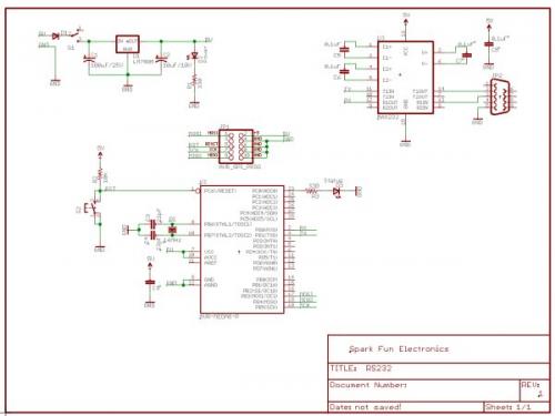
The MAX232 circuit that we will be breadboarding looks like this:
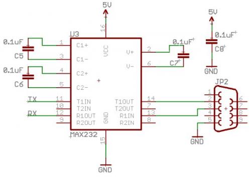
MAX232 Circuit - Eagle schematic / PDF
This MAX232 IC uses three 0.1uF capacitors (C5, C6, C7) to operate (go read about 'charge pumps'). You must have these installed. The forth (C8) is what is called a 'decoupling cap'. As the MAX232 IC switches various signals (from +/-12V to 0/5V) it uses bits of current. Because it needs these bits of current in bursts, it can disrupt your 5V supply. The C8 0.1uF capacitor helps 'decouple' or remove the ill effects of this IC (switching back and forth) from your power supply. This decoupling cap should be placed near the VCC and GND pins of the IC. This helps remove noise from your power system. Will your breadboard work without decoupling caps? Sure it will! Go without! But the day will come when something stops working and you're not sure why. Could it be my code? Do I have a short somewhere? A disconnect? Or perhaps I don't have enough decoupling caps?
A decoupling cap is meant to provide a quick burst of energy if the power supply dips down - sort of like a UPS system for your IC. The further the decoupling cap is from the IC, the less ability it has to provide that quick burst (long wires have intrinsic capacitance of their own). It's always good engineering practice to have at least one 0.1uF cap near any IC. Placing them within 0.5" of the VCC and GND pins is good. Placing them all the way across your breadboard won't do harm, they just won't provide as much help.
JP2 is a DB9 connector. It's called a 'DB9' connector because it contains 9 pins and is used universally for serial connections. You'll need a male to female serial cable to connect your breadboard's DB9 connector to the computer. The 'male' end of the cable has the metal pins, the 'female' end has the black colored plastic that receives the pins. If you look very close at a DB9 connector in real life, you can just make out some small numbers next to the holes.
So what all does this do? The ATmega168 is going to send 5V signals to the MAX232 IC. The MAX232 IC in turn will convert those 5V signals to +/-12V RS232 signals that the computer can understand through the DB9 port on the back of the computer. Admittedly this can be a bit ugly to setup at first. Will you believe me that once setup, this will be your life-line to sanity? The serial connection is everything! You'll need one on almost every application you do.
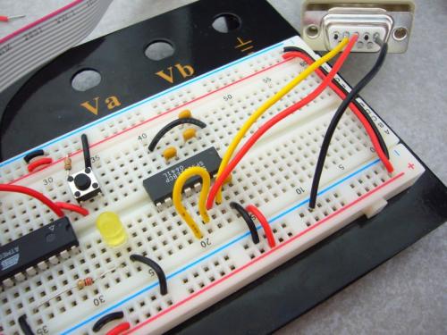
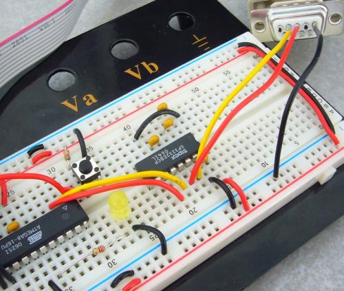
Breadboard with MAX232 and large loop-back jumper installed
Once you have everything wired, you'll need to open up a terminal program. If you're playing under Windows, you can open up the included 'Hyperterminal' program normally located under Programs->Accessories->Communications. Linux and Apple people, you probably know how to get a terminal program running (sorry I can't be more help!).
All terminal programs have the same basic function: to do serial. All you need to specify is a few simple rules to get your micro playing successfully with your computer. Let's just get through the Hyperterminal screens:
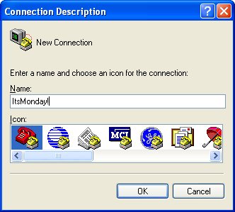
Call it whatever you want
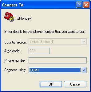
More than likely, the serial port on your computer is COM1
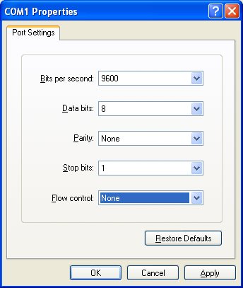
You want 9600bps 8-N-1 without flow control
The main settings are 9600bps and 8-N-1. This means that the micro and the computer agree to talk at a rate of 9600bits per second (bps) and that each byte will have 8 data bits, with no parity bit, and only 1 stop bit. This '8-N-1' is very common and basic. If you like pain, go read about parity, 1.5 stop bits, and 5 data bits. No one really uses it in the breadboarding world.
Mkay, you've got hyperterminal open and kicking. You've got your MAX232 (or equivalent circuit) built up and powered on. Before you connect it to your micro, you should test that the MAX232 circuit works. The easiest way to test a MAX232 circuit is to tie TX and RX together. It's called a 'loop-back' (the big yellow wire pictured above). Pretty self explanatory, but just follow along:
When you press the 'A' key on the computer in the hyperterminal window, a series of 1s and 0s get generated and pumped out the serial port on the back of your computer (8 bits: '01000001' to be specific = 65d = 41h - see www.asciitable.com for more info). These 0s and 1s hit the MAX232 on your breadboard which dutifully changes these RS232 signals to TTL signals. The 0s and 1s get asserted on the R1OUT pin. Because you've tied the TX and RX pins together (R1OUT should be shorted to T1IN) these 0s and 1s get sent right back out the MAX232 and down the DB9 serial cable. Upon hitting the computer, the computer 'sees' these 1s and 0s and says 'oh! there is a device passing me the ASCII character A'. The computer then displays the character 'A' in the hyperterminal screen. This is the essence of a loop-back test. If everything is kosher, you should be able to jam away on the keyboard and see those letters echoed back to the terminal window. Pull the jumper out and the characters should stop echoing. Got it? Use it! In the future, when you need to test a serial interface, short TX and RX together to make sure things are working correctly.
All right, you've got the MAX232 working correctly. Now connect the TX and RX pins of the ATmega168 to the MAX232 circuit.
ATmega8 with power supply and MAX232 circuit. Eagle schematic / PDF
You may have noticed C9 magically appeared next to the ATmega168 in the schematic above. This is a 0.1uF decoupling capacitor for the ATmega168. A 0.1uF capacitor places near the ATmega168's VCC and GND pins will help reduce power supply noise being injected into the ATmega168. Again, your board will more than likely run without decoupling caps but I just want to instill in you a habit of using 0.1uF like candy.
TX and RX connections between MAX232 and ATmega8
Savvy travelers will note (upside down) the picture MAX232 IC is actually a SP3232(EBCP). What is this 'SP3232'? It's a the Sipex generic of the MAX232. Notice the '3' in front of the 232? The original MAX232 ICs were designed to interface 5V logic to RS232. Because circuits started to run on lower voltages (3.3V for instance) the IC manufacturers had to redesign the MAX232 ICs to be more efficient so that they could take this lower voltage and boost it up to 12V for RS232. Hence the 3V designation 'SP3232'. This IC can input 3V TLL signals and successfully convert them to RS232. We are operating our breadboard at 5V but we are able to run our MAX232 from 3V up to 5V without problems.
Trivia: In the picture above, which IC is the older sibling? These ICs have simple date codes: 0641 and 0625 means both ICs were manufactured in 2006 in the 41st and 25th weeks of the year.
You should now have the hardware in place to allow you to do printf statements. Let's mess with some code!
Feedback from a reader:
"Friends don't let friends use hyperterminal. It is one sucky program. TeraTerm works much better."
We agree. Hyperterminal is a bit buggy and can lock up. TeraTerm is much better. However, since nearly every Microsoft installation on the planet has Hyperterminal already installed, we stuck to using it to ease readers into serial communications. In general, once you get over the serial hurdle, stop using Hyperterminal and start using TeraTerm.
You can get all the parts for this lecture here.
We love feedback! Please report typos, comments, or recommendations to spark@sparkfun.com.
Lecture 1 - Background and Power Supply
Lecture 2 - How to Get Code Onto a Microcontroller
Lecture 3 - What is an oscillator?
Lecture 4 - UART and Serial Communication
Lecture 5 - AVR GCC Compiling
Lecture 6 - Soldering Basics
Lecture 7 - SMD Soldering
Lecture 8 - Eagle: Schematics
Lecture 9 - Eagle: PCB Layout
Lecture 10 - Eagle: Creating a new part
Common Mistakes, Tips and Tricks
For anyone who is struggling with this Hyperterminal did not work on a simple rs232 loopback test where I put pin 2 into pin 3 on the db9. Switching to teraterm fixed that, so I knew at least my usb-serial dongle worked.
The second problem was the sp3232 will not work as pictured and described in this tutorial. You must connect the caps at pin 2 and pin 6 to ground as described in the sipex datasheet for the part. So you need 5 caps. Junctioning pin 2 and 6 with one cap does NOT work. At least not with the chip that sparkfun shipped me.
Hey,
How did you guys manage to put the wires in the db9 cap without soldering?
Christian
Are pins 2 and 6 of the MAX232 chip really supposed to be connected together with a 0.1uf cap? All the other schematics I've seen have 2 and 6 going through 22uf caps to VCC and GND respectively.
I just finished building this circuit and it did not work. After reading some of the other comments I decided to try a different circuit design. I found the website http://sodoityourself.com/max232-serial-level-converter/ helpful and I followed that schematic and it worked on the first try. If you want to get this circuit to work skip the 0.1uf capacitor between pins 2 and 6. Instead connect a 0.1uf capacitor between pin 2 and +5 volts. Then connect another 0.1uf capacitor between pin 6 and ground. As soon as I made that change it started working.
Hey, could I use the MAX232 (SP232) to control multiple serial devices? Not at the same time, I want to communicate with one devices and get its response, then communicate with the other devices and get its response. Then depending on my conditions, using the two responses as data, I will send a command to the second device. All using RS232 and an Atmega328P. Or would the uC need 2 UARTs? Or even bit-banging GPIOs, but then I guess I won't need the MAX232?
I am making an adapter for conversion between UART at LV CMOS 2.5V and RS-232. I think MAX232 chip is not useful for this as it works only for 5V CMOS/TTL logic levels. I donot want to use USB-serial interface. Any suggestions how I can make this UART/RS-232 adapter ?
I'm a little confused here and wondering if someone can help me out. I've been following the tutorials up to now and this is the first one where one of the pieces needed to complete the tutorial isn't available or easy to figure out substitutes for.
Basically I have two problems:
So I found this: https://www.sparkfun.com/products/9718
Am I correct in assuming that this cable solves both problems above in that it's a USB based serial interface and, because it's already running at 5V, it replaces the MAX323?
The FTDI cables work well as USB to serial converters, but there are also RS232 to serial shifters available as well, such as this RS232 Shifter Board. It depends on what you specifically need for your project.
for linux distros you can just use the SP Terminal or GtkSerial termnal right
Is anyone else having an issue loading the pictures on this page?
+1 to the pictures being gone, SF can this be fixed ASAP??
Same here. I was wondering if It was only me. I tuned off my Adblock Plus. But that wasn't it.
Where did all the pictures go?
So.... how about a USB option? Is this MAX232 chip the right tool for USB? I don't want to buy this kit and an adapter from db9 to USB to find out I could have just used a different chip with a USB cord. Not even mentioning a USB option in the tutorial kinda sucks. The laptop I'm using was built in 2004 and only has USB ports. This is not a new thing.
So here I sit with a little blinking LED, a thirst for knowledge and a pocket full of money. What next?
most of these are meant for desktops if your computer has an option for a parallel port one of those may have it or you can just use a USB to rs232 converter for only $5, $10, $15 bucks
Just a side note: if you are like me and have PuTTY open 24/7, you can use this familiar tool with serial communication also. I have my Bus Pirate, Adruino and FTDI-breakout in saved sessions along with linux servers.
I can confirm that this capacitor layout simply does not work for the very common (pin-compatible) max232a subsitute, the sp232acn. Connecting pins 2 and 6 via a capacitor instead of to Vcc and Ground causes very unreliable operation at 38400bps, with about one out of ten characters getting through correctly.
As a bunch of people have said, nobody has serial ports anymore. It would be very, very nice if some kind sould at sparkfun would update the tutorial to describe how to do this out of a usb port.
If you are getting garbage messages across serial, make sure to check that you have the right parts in your kit. I got a 10 MHz crystal instead of the 16 MHz. I spent way too many hours playing with fusebits and my wiring to eventually realize that my crystal wasn't 16 MHz.
so i wired up the max232 and was using a usb-serial converter from pololu from another project to talk to terra term and completely forgot that the converter is LOGIC LEVEL! DOH!
As far as I can tell it still works, can/should that damage the chip though?
I'm typing but don't see anything....
I've connected TX and RX together too. Does anyone know what can be wrong here? Or is it just my wiring?
Are you using hardware or software control for the terminal program? Even with the TX-RX connection, if you haven't connected DTR-DSR, and RTS-CTS together, you may not see anything. Easy way is to turn off hardware and software control in the setup for your terminal program. I am using minicom in Linux, and the FTDI USB-232 breakout board and I had to do the same thing to test that board, even though it is for a GPS receiver and not the M168.
I am working through these using Linux tools. In this case I used minicom as my terminal emulator. Works pretty well!
http://herdingelectrons.blogspot.com/2009/11/installing-and-testing-serial.html
Can some help me here.Do I need the JP1 (AVR_SP1_PROG) connected to the breadboard before i can program the controller?
I am getting a "process exit code: 2" error.
I have been able to compile the the C file
Has anyone had a problem uploading their hex code to their AVR while PD0/PD1 is connected to pins 12/11 of the max232? I use AVR Studio w/ avrdude to upload via USB from Win Vista to an ATmega328p on an Arduino board with a serial console RS232 to a FreeBSD box connected via the max232.
When I run avrdude to upload the hex:
avrdude -p m328p -c avrisp -P com3 -b 57600 -F -U flash:w:zork.hex avrdude:stk500_getsync(): not in sync: resp=0xff avrdude: stk500_disable(): protocol error, expect 0x14, resp=0xfc</code When I disconnect the RX/TX between the ATmega328p and the max232 it uploads fine. Any suggestions? Thanks!Solved!
So like many folks, I don't have a serial port. It would really be nice, BTW, to add some tips/hints for those without serial ports to these tutorials . . .
Anyhow, I've gotten this far using the USBTinyISP programmer, but now I'm stumped. It seems I should be able to use the FTDI USB/Serial/TTL cable I use to communicate with Arduino, but I can't seem to get it working . . . do I still need the MAX232 circuit? Do I need something different?
I'm having a similar problem (no db9/db25). I'm thinking if the max232's purpose is to change voltages from 5V to 12V and vice versa then we shouldn't need it if we are going from 5V (AVR chip) to 5V (USB). is there something else the chip does that I'm missing.
Any reason I can't hook this directly up and go from there? http://www.sparkfun.com/commerce/product_info.php?products_id=718
Hi Michelle,
The EIA-232 chip I use is the ti max232n [http://focus.ti.com/lit/ds/symlink/max232.pdf]. The datasheet has detailed information and seems more designed for implementing a full/partial RS-232-F standard without having a lot of external components to generate RS232 voltages from 3.3 or 5v and then convert them back down to CMOS/TTL levels (along with a few other niceties). As for going from AVR to USB, maybe this could be a start:
Check out the schematic at the bottom
Good luck!
My computer has NO serial ports aside from USB. I put together the USBTinyISP programmer so I could program the chip and have done the previous tutorials successfully. Now what? Do I get a USB DB9 adapter? Suggestions welcome!
Another thing that you could look into is to see if your motherboard has a serial interface, frequently the serial pinout exists on the mobo, but is not hooked up to an RS232 serial port since nobody besides wirebiters and nerds needs one. you can then find a serial port on-line that will interface with the pinout for like 3 bucks. The same is frequently true of parallel ports as well.
I got this to work without serial ports and without any major difficulty using the FTDI TTL to USB serial converter (http://www.sparkfun.com/commerce/product_info.php?products_id=9717). I'm actually using a 3v one I had bough for Xbee use. It was really easy. Orange wire is Tx, Yellow is Rx. Connect them for loopback. I used minicom since I'm on linux. I had to minicom -s at first, set the serial device to /dev/ttyUSB0. The loopback didn't work until I disabled hardware flow control.
Hi cdub, have you been able to use the USB to DB9 for this tutorial?
Did you use the USBTinyISP instead of the DB25 connector to program.
My computer does not have a DB9 or a DB25 either.
I have successfully used a usb to DB9 for serial comm with the RS232. Note however that adapters do not work with programmers. That goes for parallel as well.
Actually Vista does not come with Hyperterminal. At least my installations of Vista home premium don't have it. If for some reason I need a terminal program then I have to use a 3rd party package.
See http://forum.sparkfun.com/viewtopic.php?t=12344