
Beginning Embedded Electronics - 6
Lecture 6 - Soldering Basics
Say it with me - 'Yes, I really can solder that'. Yes, you really can solder that and anything else.
First, we will solder a through-hole component kit. Here are the ground rules for soldering:
- Rule 1: Irons get hot. Don't poke your lab partner in the eye with it.
- Rule 2: You need to wet your sponge. This may seem counter-intuitive, just do it. I hate seeing people ruin irons because they're too lazy to get the sponge wet. This wet sponge is used to clean the corrosion on the tip of the iron. A dry sponge does nothing but damage the tip. Every time you pull the iron from the stand, it's a good idea to swipe the tip on the sponge just to clean it off and get a nice silver tip - it will allow you to solder much quicker and much cleaner.
- Rule 3: The point on the iron-tip is NOT the hottest part. This takes some practice but learn to use the side of the tip near the point. It's all about getting the heat to flow from the iron to the joint. If you sit in one spot for a long period of time and nothing is flowing, take a step back, clean your tip, add a bit a solder to the tip, and try soldering the joint again.
- Rule 4: The soldering iron is only there for heat, not solder. You use the iron to heat two things - the part and the board, and then you add solder to the two heated parts. You do not add a glob of solder to the tip and then rub this mess against the two things you're trying to solder together. Use the side of the iron (remember, not the point) to heat the two parts while adding solder from the opposite side.
- Rule 5: Perfectionism kills. If you solder a joint, and it looks alright, let it be. Do not solder, then touch up, and re-solder, and then have to touch up a third time. This heating/reheating stresses the PCB (printed circuit board). You will quickly delaminate the board, lifting traces, pads, and destroying the board. Do this for fun on your own time.
- Rule 6: This is really getting ahead of ourselves here, but it's good to hear as many times as possible. When soldering joints that have a lot of thermal weight, heat the joint up for an additional 5-10 seconds. When you solder to a big part or a pad that has a lot of copper attached to it (very common with GND connections), it takes a few extra seconds for the iron to pump enough heat into the part to get it to the correct temperature to form a connection. If you notice your iron tip feels 'sticky', or if you see the solder balling to the pin instead of flowing to the joint, this is because one part of the joint is not hot enough. Hold the iron on the joint for a few extra seconds and allow the solder to flow correctly.
Here is a short video to demonstrate how to clean your iron tip, solder a through hole component, and clip off the extra leads.
Now about irons:
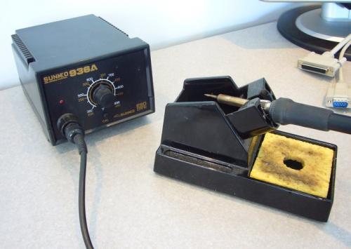
This is my cheap-o Sunkko iron. It was under $100, it can solder lead-free solder just fine, and I use the standard included iron tip. You don't really need a digital read-out for home use, but do get an iron that has an adjustable temp dial. I set mine temp to about 350C for leaded solder. Notice my sponge is wet!
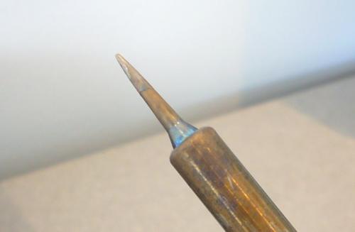
A cold iron tip. You can see the barrel and upper area of the iron are discolored by heat over time. No problem. You do not need a needle-sized iron tip to solder SMD devices. This is a common fallacy. This tip works very well!
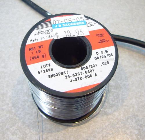
Here's my solder. I stole this from work because
- It's leaded and we use lead-free for production.
- It's 0.020" diameter which is really too thin for production. Because it's so thin, the assemblers would have to use many many inches of solder to solder larger joints (lke DB9 connectors). Smaller diameter solder helps you control how much solder goes into very tight pitch joints but it's not magic - it is not required. Just don't buy the solder at the hardware store that they sell for copper pipe plumbing, that stuff is ridiculously thick.
This solder is SN63PB37 meaning it's 63% tin and 37% lead. It's also called 'rosin core solder' because it has an organic core of rosin. As you melt the solder into the joint, a small amount of rosin inside the core will come out and help the solder flow. Rosin basically changes the surface tension of the solder allowing it to flow better (we're talking about liquid metal after all). Rosin will burn off and that's the small amount of smoke you see while you're soldering. Standard rosin smoke is not harmful! It has been known to irritate some people's eyes but I've never known anyone to have a problem with it. When in doubt, get a fan or open a window.
Note: Lead is known to be a carcinogen. In general, don't eat the solder. Wash your hands before you eat and you should be safe.
This is a 1lb spool which should last me until 2020. $18.95 from JB Saunders in 2005. JBSaunders is a surplus shop in Boulder, CO. They sell some handy tools and supplies but it's not your standard hobby shop - it can be tricky to get help some days. Solder aficionados may watch the DOM (date of manufacture) and claim that solder will go bad at some point. I have no idea. I imagine the rosin may change slightly over time but this solder is probably good for many years to come.

Here is a hot iron, with a blob of oxidized solder on the tip.
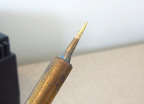
A quick double swipe on the wet sponge and the tip is clean and shinny. This is the iron you should be soldering with! Keep your tip clean and shinny. Clean it often. Wipe it on the sponge every time you take it out of the base. Add a bit of solder to the end of your cleaned tip to increase heat flow.
That's the basics. Soldering takes practice! Just go and get your hands dirty already.
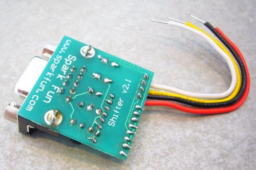
The Shifter board assembled
You will be assembling the RS232 Shifter board.
Please note: the component placement on the shifter board in the photos in this tutorial might not be the same as the shifter board you purchase. Make sure to follow the silkscreen indicators on the board you receive for proper component placement.
This board is a MAX232 equivalent circuit meaning it does some dirty tricks to convert RS232 signals to TTL level signals. It does this with a few pennies worth of parts instead of a proper MAX232 IC.
The benefits of the shifter board vs. a conventional MAX232 circuit: * The shifter board is smaller than a MAX232 DIP with its charge-pump caps * Cheaper * Works at voltages down to 2.5V (compared to the MAX232 that only works at 5V)
Problems with the Shifter board: * It's a bit dirty, meaning it does not follow the proper RS232 +/-12V convention (shifter board only puts out -3V to +5V) * It will not operate faster than 115200bps (some MAX232 ICs can operate up to 1 mega-bit per second) * It only has TX/RX where a MAX232 has TX/RX/CTS/RTS (additional control lines)
In response to problem 1 - I've never come across a modern computer that the shifter board does not work. This is because the RS232 ports on modern computers are designed to deal with poorly designed serial devices! So even though our shifter board can't quite get to the -12V and +12V, the computer can still understand what it's trying to say.
Problem 2 - Windows simply can't handle serial speeds faster than 115200bps (well, not without some serious finagling). The shifter board works fine at this speed so the MAX232 has no real advantage for the every-day application.
Problem 3 - Almost all the serial interfaces you will be building, hardware flow control (CTS/RTS = clear to send and ready to send) is rarely used. The shifter circuit is simple. Replicate it twice if you want flow control.
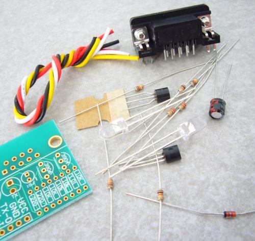
So let us build up this kit and replace the MAX232 circuit in the breadboard with our shifter circuit. Always lay out all your parts to make sure you've got everything you need.
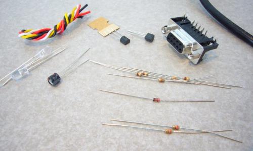
Plated through-hole (PTH) resistors have color bands on them. Surface mount device (SMD) resistors have readable numbers on them. I can't read the color bands on resistors to save my life, but your multimeter can! The shifter kit is easy to tell which is which - there are five 10k resistors and two 220Ohm resistors.
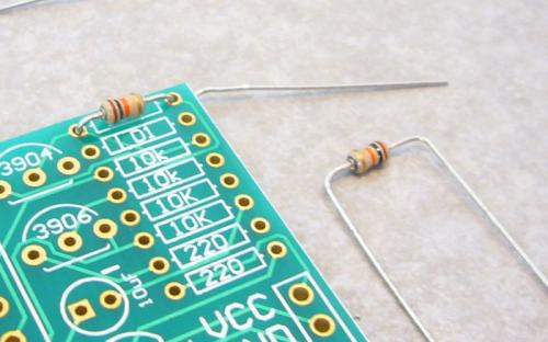
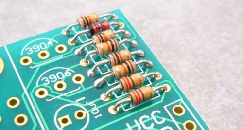
Resistors are non-polarized meaning they can be inserted into the board either way. You can pre-bend the resistor leads if you like. After the resistor is inserted into the board, bend the legs out the other way so that it stays in place. Pull out your iron and solder the resistor from the bottom side of the board.
Hold the iron against the PCB and the leg of the component. Insert solder into this trio. It should melt as you add it. If not, re-orient the iron to get better heat conduction. It's not hard, just practice. Once you've got the two joints soldered, clip off the legs.
Clip off the legs. Don't worry about clipping the legs absolutely flush. Doing so can stress the mechanical nature of the joint and the PCB.
The kit has various indicators showing the assembler how to orient parts. Pay close attention to these and the resistor values.
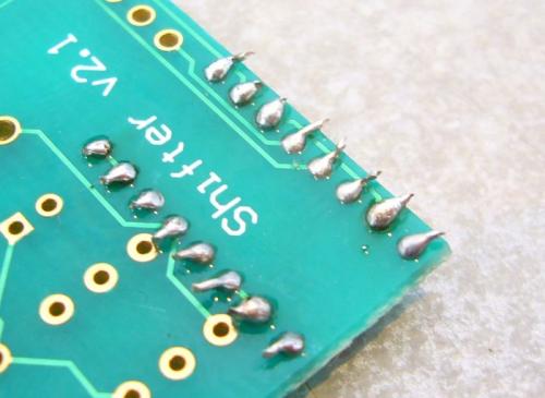
Notice the small pool of solder at the base of the resistor legs we just soldered in? This is good. Enough solder was applied to come through the holes from the bottom of the board to fill all the way through the via.
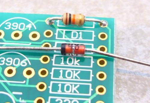
The single diode in the kit is polarized so you'll need to get the orientation right. In the picture above, the black line on the diode matches with the white line on the silkscreen.
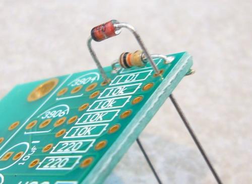
Soldering the diode like this would be bad. Make sure you get the component flush against the PCB, within reason. Some components (like the transistors we're about to solder) ride above the PCB. Solder up the rest of the resistors.
All the resistors and diode
Soldered and trimmed. Notice the small amounts of residual flux - it's the clear, shiny, sticky material left of the board. For production assemblies, this flux is cleaned off with a light solvent or rubbing alcohol. Flux is slightly acidic and will degrade solder joints over a period of years. For our purposes, this flux is ok and shouldn't cause any problems.
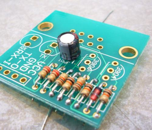
Solder in the electrolytic capacitor noting the '-' sign polarization matching with the silk screen.
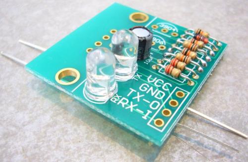
LEDs installed. Note the flat side of the LED matches the silkscreen polarization.
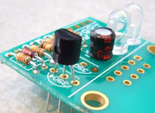
Install the 2N3904 and 2N2906 transistors. Note the flat side of the BJT transistor matches the flat side of the silkscreen. Make sure you get the correct '3904' and '3906' labeled parts in the correct spot.
Here is a short video to demonstrate how to clean your iron tip, solder a through hole component, and clip off the extra leads.
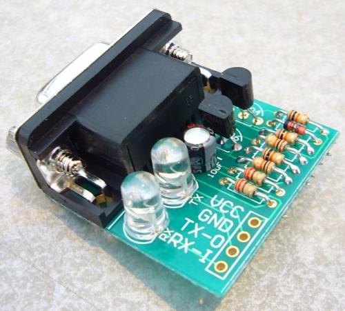
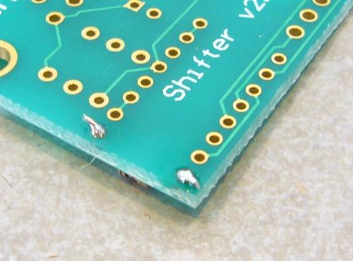
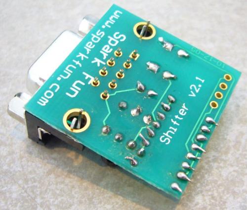
Install and solder the DB9 connector.
You can see now why it would have been a bad idea to solder the DB9 connector first. The PCB would have been at an angle during soldering.
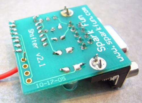
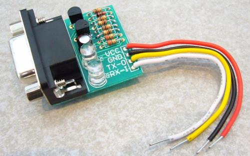
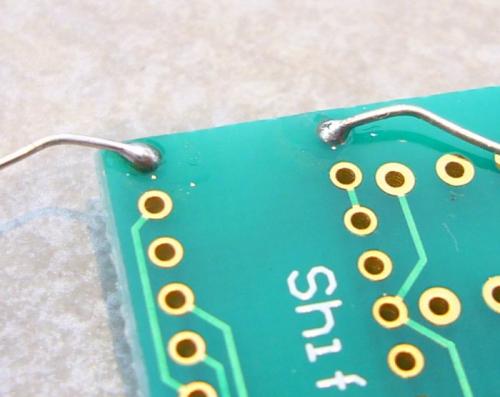
Solder in the four connection wires - VCC, GND, TX, and RX. Pick your own color scheme. I only recommend that red and black go to VCC and GND respectively.
The shifter board, all assembled!
Guess how we're going to test it? A loop-back jumper of course! Plug the shifter board into your breadboard, VCC and GND, and insert the TX/RX wires into one row, shorting them together.
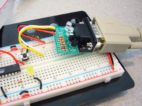
Power your board, pound some characters into hyperterminal and verify that you get an echo. You should see the TX and RX LEDs blink briefly. Congrats! You now have a serial connection for all your future breadboard prototypes! This should open up some significant space on your breadboard and allow you to skip building a MAX232 circuit for future breadboard projects.
In the end, I use the shifter board on all my breadboard prototyping and a conventional MAX3232 circuit on my PCB designs. Sorry to confuse you so much. When you solder together as many prototype PCBs as I do, you really want to limit how many solder connections you have to solder. Inserting through-hole components for the shifter circuits takes much more time than a MAX3232 circuit. I also like the MAX3232 circuit because it has fewer parts that could break.
We love feedback! Please report typos, comments, or recommendations to spark@sparkfun.com.
- Lecture 1 - Background and Power Supply
- Lecture 2 - How to Get Code Onto a Microcontroller
- Lecture 3 - What is an oscillator?
- Lecture 4 - UART and Serial Communication
- Lecture 5 - AVR GCC Compiling
- Lecture 6 - Soldering Basics
- Lecture 7 - SMD Soldering
- Lecture 8 - Eagle: Schematics
- Lecture 9 - Eagle: PCB Layout
- Lecture 10 - Eagle: Creating a new part
- Common Mistakes, Tips and Tricks
I have to ask...
Did it?
Spark Fun Guys, please check images links, cause many tutorials have broken links to images.
Many thanks! are invaluable information for us.
By the way, this a good, cheap and easy to use soldering iron I have one and 1/16, 1/32 and 1/64 fantastic soldering tips, works great!
D'OH! I have learned much from this kit. 1) Shorting the tx and rx leads together while plugged in to your computer's serial port is NOT an adequate test. Without power and ground on the 4-wire side, the board will just sit there and you'll see no loopback echo on your communication program. Read the test instructions carefully! 2) It's normal and correct that the vcc on the 4-wire side of the card will be 5 or so volts negative relative to the ground wire. After I double-checked all my components and triple-checked my soldering with a magnifying glass, I plugged my card into the device I needed to talk to and found that it worked perfectly well.
The LEDs in my level shifter kit are the bead kind, not the flat-side case kind. From the web it looks like the flat side is usually on the negative (short-lead) side of the LED.
I have found securing the board with a bit of tape, hemostat, or card holder to prevent movement will relieve a good deal of frustration.
I have learned, through many years of soldering, the prudence of applying a bit of solder to the tip of the iron before returning it to the stand. The solder will oxidize instead of the iron tip to be easily removed by the wet sponge. An oxidized tip will produce much grief when soldering.
Finally, clean leads of the parts to be soldered with a good grade of alcohol and the solder will flow fully into the joint. (rubbing alcohol is bad stuff).
Enjoy.
I've just solder this device from your components. As Neil said the components were slightly differed from tutorial's ones.
BUT! I've faced some problems with connections
1. Loopback test works fine
2. RX and TX seemed to be inverted:
- when RX(on the shifter board) connected to RX(on the AVR), TX to TX: TX led blinks but nothing happend in TerraTerm
- when RX connected to TX, TX to RX, RX led blinks and I see an echo in my TerraTerm.
Could you explain it - why? or give some recomendations to deeper test a board.
Do you need any special type of sponge? I know sparkfun sells a brass one but can you use a regular kitchen sponge?
The soldering does not look good at all! YouTube.com has excellent videos on soldering. See this one and note the incredibly well-done on the soldering. http://www.youtube.com/watch?v=I_NU2ruzyc4
It's nice to have somewhere to refer people when they want to learn how to solder!
Excellent tutorials!
2) The RS232 shifter board kit that I ordered from Sparkfun was slightly defective. The board failed the loopback test. The Tx LED was lighting but the Rx LED wasn't. I used my multimeter to identify that the trace between my LED - terminal and the Rx-I connection. I fixed this by manually soldering a wire between the two connection points.
A couple of notes on this tutorial.
1) The RS232 shifter board kit that I ordered from Sparkfun in September 2008 was slightly different than the one illustrated in this tutorial. You should still be able to follow the silkscreen board. Just make sure to put the diode in the spot marked 1N4148, rather than D1. Also, the silkscreen spots for the 220 ohm resistors are marked 330 ohm. I think either level of resistor will work.