
Beginning Embedded Electronics - 7
Lecture 7 - SMD Soldering
You can get all the parts for this lecture here.
Remember, 'Yes, I really can solder that'. It's time to put Simon together! This SMD kit will show you just what it takes to solder SMD components.
The SparkFun SMD Soldering Workshop is a pseudo-class that we've been working on at SparkFun. We hand out some paper materials and teach people these lectures and have them assemble a Simon kit. It's a lot of fun! You can download the handout here that contains the following material and a bit more.
Here are the various files you will need:
- Simon Assembly Procedure (follow the steps! [5MB])
- Simon Board (component print)
- Simon Eagle Files (for trouble shooting)
- Simon ATmega168 Firmware (for programming)
- Simon (Old) ATmega8 Firmware (for programming)
- Simon Schematic (for general reference)
Here is some good information for SMD soldering:
- SMD Soldering Basics (big 4MB)
- SMD Soldering Workshop
Here is some basic code examples to show how to control various parts of the Simon board:
For more soldering tutorials, there are some great videos and instructions on the SparkFun website here. Read up on those basics as well.
Two words : solder wick. Get some. Actually, get a lot.
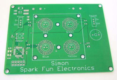
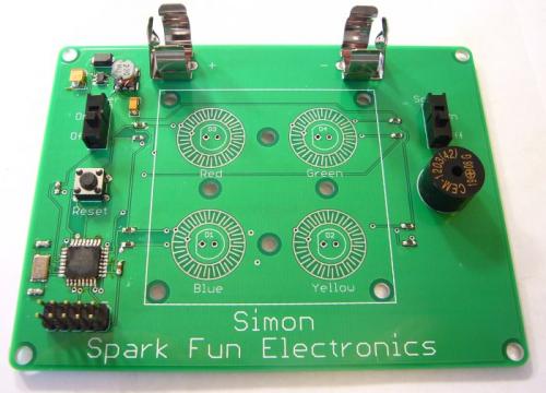
Simon SMD Kit
This is what we will be assembling today.
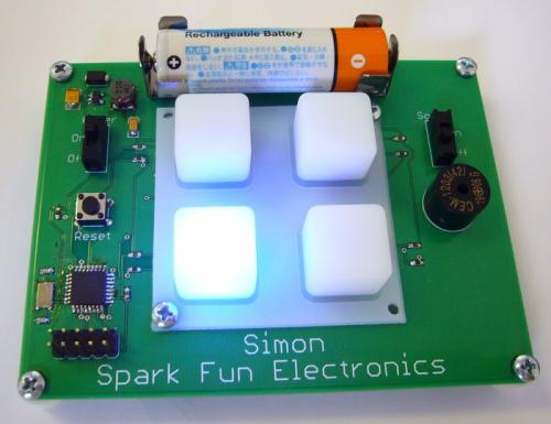
Assembled and blinking!
Make sure you've got all the components you need. Remember, SMD resistors are marked, capacitors are not so be sure to correctly identify the caps by writing on the tape immediately after you cut it off the reel. If you've just got a Digikey bag, make sure the correct components make it back into the correct bag.
Through-hole components:
-
1 x Simon PCB
-
2 x AA Battery Clips
-
1 x Buzzer
-
2 x Slide switches
-
1 x ISP Header
-
4 x LED (Yellow, Blue, Red, Green)
-
1 x Momentary Push Button
-
6 x Screws
-
6 x Plastic Standoffs
-
1 x Rubber 4-Button Pad
SMD components:
-
5 x 10k Resistors
-
4 x 220 Ohm Resistors
-
1 x 47uF Capacitor
-
1 x 10uF Capacitor
-
1 x 0.1uF Capacitor
-
2 x 22pF Capacitor
-
1 x 16MHz Crystal
-
1 x MBRA140 Diode
-
1 x 22uH Inductor
-
1 x NCP1400 SOT-23-5 IC
-
1 x ATmega168 TQFP IC
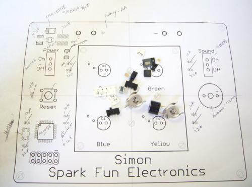
Parts and assembly sheet
We created an Eagle shortcut button to help us produce assembly sheets. Pressing Alt+F11 will turn off all the extraneous layers, and turn on only the layers we need for assembly purposes. Pressing F11 will turn all layers back on.
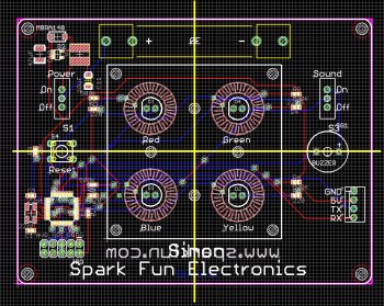
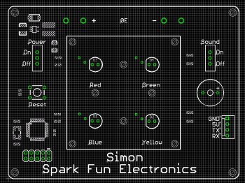
All layers vs. assembly layers
Once you have just the assembly layers turned on, you can print the assembly sheet. I like to scale this print out by 3 so that the printout is 3 times larger than actual size. This helps when writing component values next to tightly packed components. With the printout in hand, write in all the pertinent component values so that you know what goes where.
When soldering a mix of through-hole and SMD components, always start with the smaller, tighter pitch devices. If you go jumping into the easy ones (the power switch, LEDs, ISP header, etc), you will run the risk of touching the iron against these larger plastic items and melting them. Let's start with the power circuit:
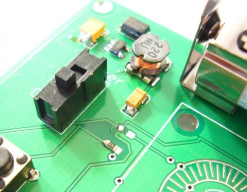
The first thing we are going to build is the DC to DC step up power supply. This will take the 1.5V from the AA battery and boost it to 5V.
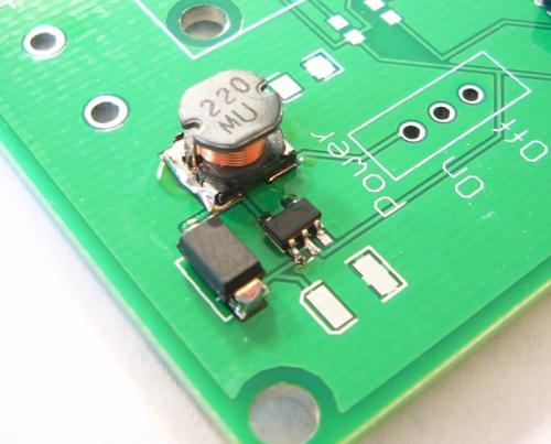
NCP1400 surrounded by inductor and diode
Be sure to start with the inner most parts and work your way out. Otherwise, it can be difficult to get the iron into tight spaces.
Let the videos begin!
Once you have the IC to your liking, solder the other pins. Don't worry about jumpers.
If you have jumpers, pull out the solder wick. Watch the video closely! First I put a blob of solder on the end of the iron, hold the wick over the jumper, then I hold the iron w/ blob against the wick. You will notice a change in color of the wick - this is the solder climbing the wick! The blob on the iron aids in transferring heat and flux to the wick and jumper. After a few seconds, the blob travels up the wick and pulls the jumper along with it. Remove the wick along with the iron (do not remove the iron and allow the wick to attach to the component). The jumper is removed.
Not so bad, right? Now let's solder the diode.
Add solder to one pad. Make sure the white mark on the diode lines up with the bar on the silkscreen. Slide the diode in, hold it in place while you remove the iron. If alignment looks good, solder down the other end.
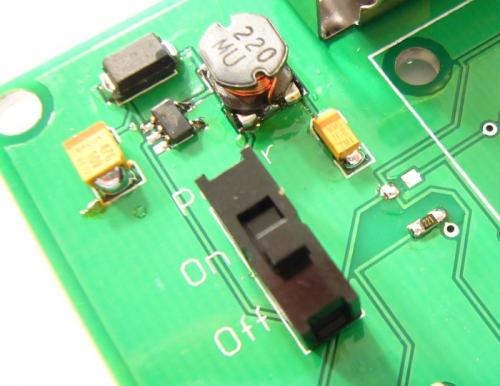
NCP1400 with inductor and diode
The inductor requires a bit more solder and patience. The footprint is pretty tight. Make sure you slide the inductor all the way over your first pad so that you can solder the 2nd pad.
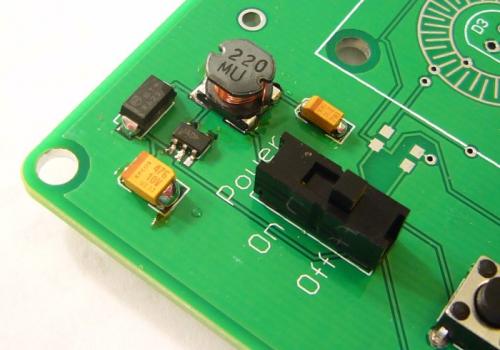
Solder on the 10uF cap and 47uF cap. Make sure you get the polarization correct. Solder in the power switch.
Solder in the AA battery lugs. They will require a bit more heat and time because they act like heat sinks. Once you have all these power components attached, insert a AA battery into the power clips. Be sure the '+' and '-' signs on the board match up to the battery.
Whip out your multimeter, cross your fingers, flip the power switch to 'On', and measure the voltage across the 47uF capacitor. It should read approximately 5V. 4.8V to 5.2V is fine. If you read something much lower, turn off the board immediately and check to see if anything is warm. Check your polarization of components (diode, caps, and battery). Check to make sure all the solder connections are sound. Touch up as necessary and re-test. Make sure you've got a solid 5V supply before moving on. Remove the battery to prevent accidental turn on during soldering.
Time to solder the ATmega168!
Same steps: put a blob of solder on one or two pads as the anchor. Slide the IC into the molten solder and align the IC. Once you have everything square and flush against the PCB, remove the iron. Do not worry about jumper, but do not solder more than 2-3 pads while you are doing this alignment step.
Soldering Side 1: Now that you've got the IC in place, jumper the opposite side like crazy. Make sure each pin gets heat/solder. Then go back with wick and wick away the excess.
Soldering Side 2: More of the same. Jumper, and wick away.
Soldering Side 3: If the wick starts to get in your way, cut off the used wick (once it's silver, it's not re-usable) and throw it away.
Soldering side 4: Same motions, but two of the pins should already have a jumper. Add solder to all pins like before, and wick away the extra.
The ATmega168 should now be soldered! Congrats! That was the hardest part! Let's solder the crystal next.
Add solder to an anchor pad, slide and and align the crystal so that you can see equal parts of all four pads. Solder the other four pads. Be careful not to allow solder to jumper from the pad to the top cover. The crystal packaging is ceramic (non-conductive) but the top is metal and will short pads together if you're not careful. This shouldn't harm the crystal, it just won't oscillate.
0603 Resistor pinned down
Now we have a handful of discretes to solder down. Be sure you get the 220Ohm, 10k Ohm resistors, 22pF, and 0.1uF capacitors in the correct places. They are not polarized.
Add solder to one pad (in the picture above I've added anchor solder to all components on the board), slide the component in, and remove the iron. Add solder to the 2nd pad. Add solder to the first pad if you want, to try to minimize the 'horns'.
220Ohm 0603 resistor all happy
Continue soldering all 0603 components.
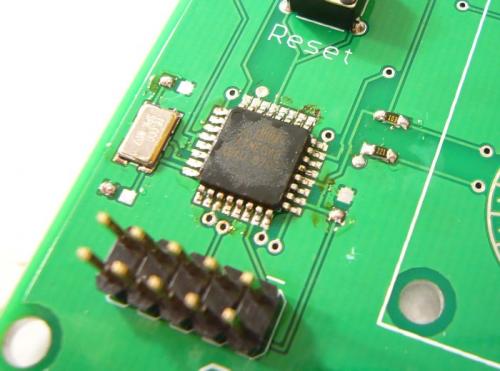
Close-up of the ATmega168
Don't worry about the gunky brown stuff too much. That's residual flux and can be cleaned off with a little rubbing alcohol if it bothers you.
Now it's time for the easy stuff! Soldering in the through-hole components!
Use the weight of the PCB to hold the ISP connector in place. Be sure to solder the ISP connector so that the long pins point up when looking at the front of the board. You will be soldering from the back of the PCB. Tack one pin down and check that the ISP connector is flush against the PCB. If it's not, re-heat the one pin while lightly applying pressure to the connector/PCB until they are flush. Now solder the other 9 pins, finally touching up the original anchor pin.
Ground pins will require extra time/heat. Don't get speedy. Childs play compared to SMD components, right?
Now insert and solder the reset switch. The reset switch should lock into place so just make sure it's flush before soldering it.
Repeat these steps for all through hole components (sound switch, buzzer, etc).
Almost there!
Notice we have not yet soldered in the LEDs. Because they are clear, we don't know which LED goes where. Also, we've been tricked in the past by mistakenly marked LEDs (the flat mark on the LED did not correctly match with the silkscreen). We first need to program the board with Simon game firmware and then hold the LEDs in place for testing.
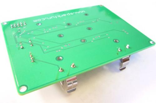
First step - add some stand-offs. This will levitate the board above your work area and avoid the possibility of shorting bits of scrap wire across the back of your PCB. Insert the AA and make sure we still have 5V on the board. If not, immediately disconnect power and check for shorts. Continuity probe if necessary. Now attach the AVR-PG2 programmer and open Programmer's Notepad as we did in Lecture 2. The AVR-PG2 programmer requires power from the board so be sure to turn on your board before attempting to program.
We will need to configure the ATmega168 to use its external 16MHz crystal. Review Lecture 3 and in a command prompt send:
-
avrdude -p atmega168 -P lpt1 -c stk200 -U lfuse:w:0xff:m -U hfuse:w:0xc9:m
If the fuse programming throws an error (it always does on the first try for some reason), select 'n' and try again. The second time, it should complete successfully.
Here is the firmware for Simon for the ATmega168. Open Simon.c in PN2, select Tools->Program and the firmware should load onto your Simon board. Now insert one of the LEDs and hold it slightly at an angle. It should light up momentarily. Turn off Simon. Whatever color the LED is, insert it into the appropriate place on the PCB, bending the legs once it's flush against the PCB to hold it in place. Solder this LED in place and repeat these steps for the other three LEDs. If the LED does not light up, flip the LED around to see if it's an orientation problem. If the LED still does not light up, check to make sure the firmware is loaded correctly.
Once you have all four LEDs soldered in place and blinking correctly, add the button pad and secure it in two places with a screw and standoff.
Simon!
You should now have a functioning Simon game! Congratulations!
Now if you are the lucky type that runs into problems during assembly/testing, there are a few things that should be checked. In order of priority:
-
Test for shorts between VCC and GND
-
Check that the board has 5V
-
Test ISP pins for shorts to GND, or shorts to VCC
-
Probe connections from ISP connector to given pins on ATmega168
-
Probe connections from pins on ATmega168 to various components
If any one of these steps fails, you should be able to localize the problem and cut traces, green wire, whatever it takes to get the PCB working.
The parts for this lecture can be purchased here.
We love feedback! Please report typos, comments, or recommendations to spark@sparkfun.com.
Lecture 1 - Background and Power Supply
Lecture 2 - How to Get Code Onto a Microcontroller
Lecture 3 - What is an oscillator?
Lecture 4 - UART and Serial Communication
Lecture 5 - AVR GCC Compiling
Lecture 6 - Soldering Basics
Lecture 7 - SMD Soldering
Lecture 8 - Eagle: Schematics
Lecture 9 - Eagle: PCB Layout
Lecture 10 - Eagle: Creating a new part
Common Mistakes, Tips and Tricks
So I just bought the kit, and thought I'd put this guy together - but the board I got does not match the board in the pictures very well at all. Notably, there seems to be nowhere for the 47uF cap to go. Without that cap, the voltage at the cathode of the Shottky diode is about 3v. The Atmega328 should sun at this voltage... but is this correct? This is a long way from what is written in the tutorial above. Can anyone clarify?
(PS The board I have is red, and dated 6-23-2009)
(correction, dated 6-3-2009)
I've completely done it - nice game.
I have to mention about 'a little' buggy .c sources: you can see port C0 used to address
1) a blueLED AND
2) a button 0
And almost all other ports especially leds and buttons I have to override to run a game properly.
My version of simod board is 6-3-2009.
Yes! I've solve my problem in this way - I take an quartz from a Lecture 3, connect it to 7 and 8 pins directly, and send my commands via avrdude.
So, ajja (a perso who make the first comment) - the simplest way to unlock a device for those who following the tutorials is to use oscillator from the tutorial 3.
I've run the following:
avrdude -p atmega168 -P lpt1 -c stk200 -U lfuse:w:0xff:m -U hfuse:w:0xc9:m
and then I can't do anything with AVR - it says that AVR device not responding. Please give me advise how to solve it.
I got the same results as you, then read through the source code. What you need to do is set the fuses to the default -- internal 1MHz, so High fuse = 0xDF, Low fuse = 0x62. After that, it works (well, except for my blue button, which maybe I soldered wrong or something).
Woo-hoo, fixed the blue button (pin on ATmega168 insufficiently soldered)
correction: new boards say "6-25-08"
I programmed the fuses like Sparkfun said, and now I'm locked out of anything further. Your fuses made the Atmega look for an external 8 MHz oscillator. THERE IS NONE on the new boards (they say "8-25-08"). Therefore, I'm locked out of any more programming, fuse setting, running, or doing ANYTHING requiring a clock cycle. Now I'll have to buy an 8 MHz crystal and cram it in. By the way, for anyone looking at this tutorial, use these fuses instead:
low fuse: 0xC2
high fuse: 0xCD
extended fuse: 0x00
...making the command like this:
avrdude -p atmega168 -P lpt1 -c stk200 -U lfuse:w:0xc2:m -U hfuse:w:0xcd:m
Oh, and the firmware is outdated. Using the right fuses, and programming your "latest" (1 year old) hex, all it seems to do is light up red and blue. When I press a button, green and yellow turn on. Nothing else.