
Build an Ardubot
Buildabot
This tutorial is intended to show the reader how to build up an Ardubot platform. There are a few different ways that it can be done, so we?re going to be a little general and show a couple examples.
First, gather all the parts:
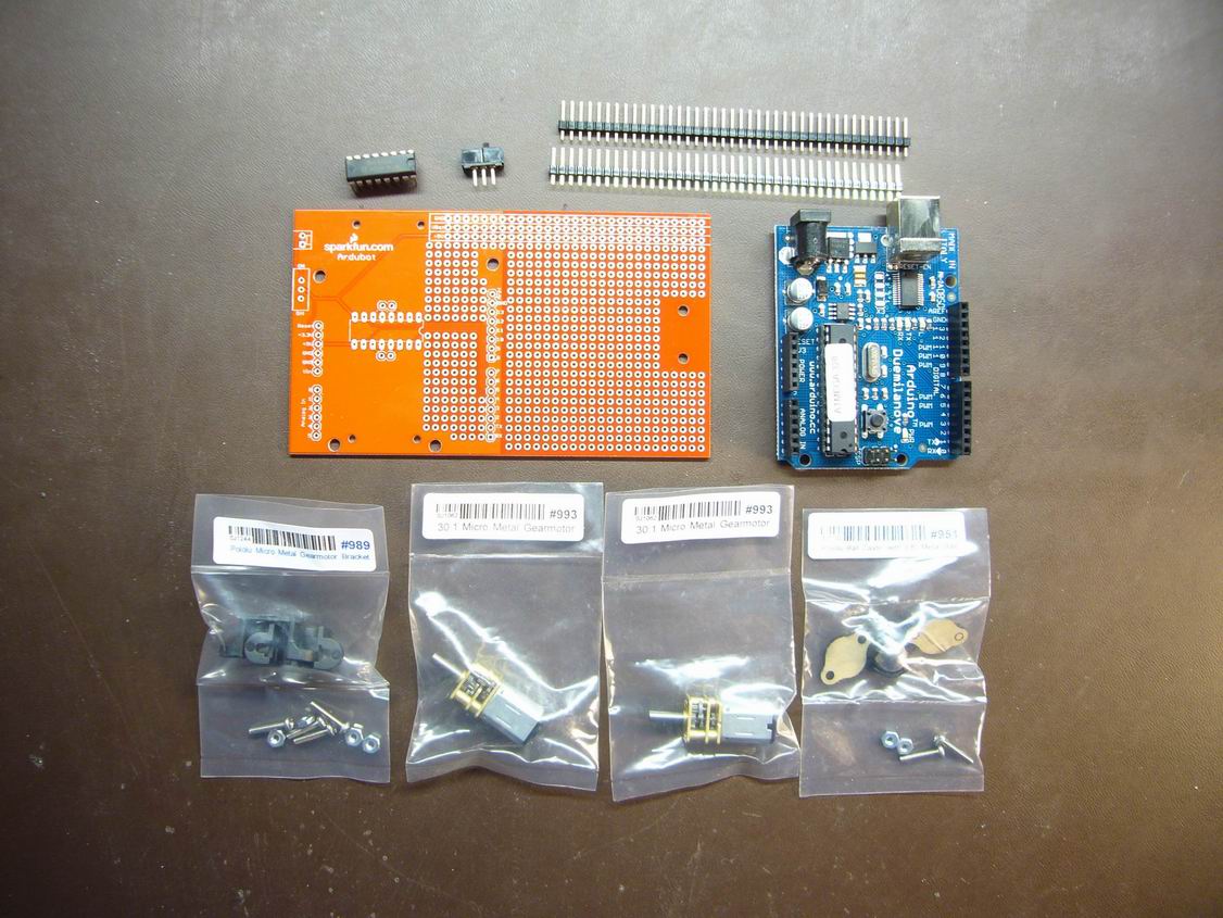
Most of the guts of the Ardubot.

A few remaining pieces.
The list is:
(1) ROB-09207, Ardubot PCB
(1) DEV-00666, Arduino USB Board
(1) ROB-08901, Wheels 32x7mm
(1) ROB-08909, 3/8? Metal Ball Caster
(2) ROB-08911, Micro Metal Gearmotor 30:1
(1) COM-00315, H-Bridge Motor Driver
(1) COM-00102, SPDT Mini Power Switch
(2) PRT-00116, Break Away Headers - Straight
(1) ROB-08898, Micro Metal Gearmotor Bracket
You could also use the polarized battery connector we sell (sku: PRT-08233). I could also have substituted the 5V, standard sized Arduino Pro board (sku: DEV-08943) for the USB version, making it slightly cheaper and smaller. And I could have used 100:1 motors (sku: ROB-08910) instead of 30:1, making it slower. These were just my choices. Your mileage may vary.
Then, solder on the bridge driver, like so:
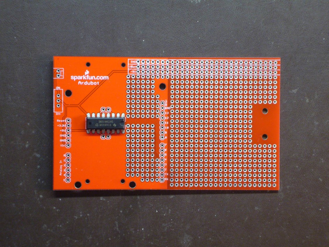
The bridge driver soldered onto the Ardubot.
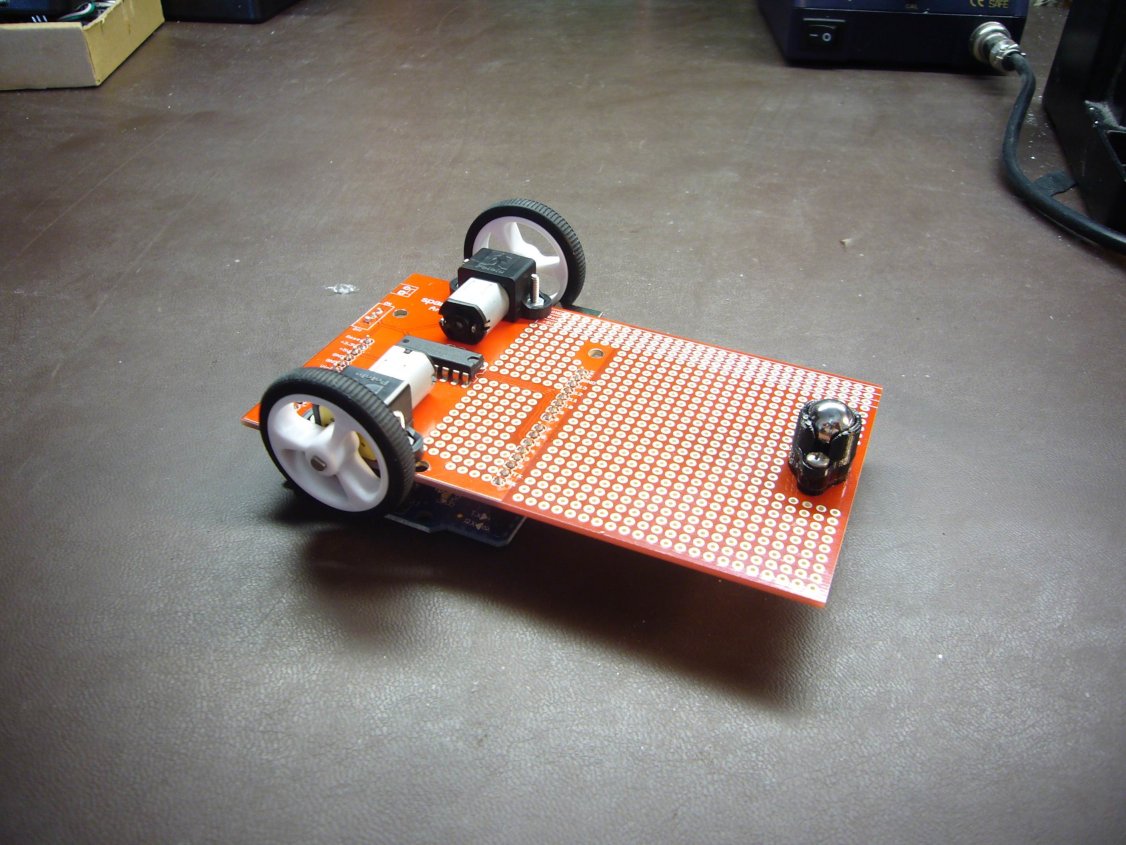
Next, install the motors with their mounts. The mount kit comes 2 mounts and hardware per package. The mount fits over the gearbox on the motor with a good fit. Just insert the nuts into the mount holes and bolt it all together from the other side of the board.

What the motors look like once they are mounted on the board.
Wheels next. You?ll have to put the rubber on the rims yourself. That?s just part of this whole DIY craze thing that?s going around. Oh, and you might want to trim the flashing off of the rims first as it makes for a better fit. The wheels are just pressed onto the motor shafts.

At this point, it looks more like a chariot, but it's getting there!
Then we install the caster. The caster comes with a couple of spacers (or backplates, I suppose), screws and nuts for mounting. Just bolt it all up according to your ride-height preference.
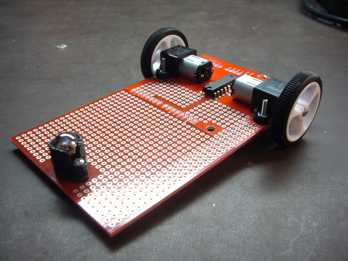
The caster bolted to the board.
Now's a good time to solder the motors to the board. I used a pair of 1x2 male headers, bent to fit and soldered up.
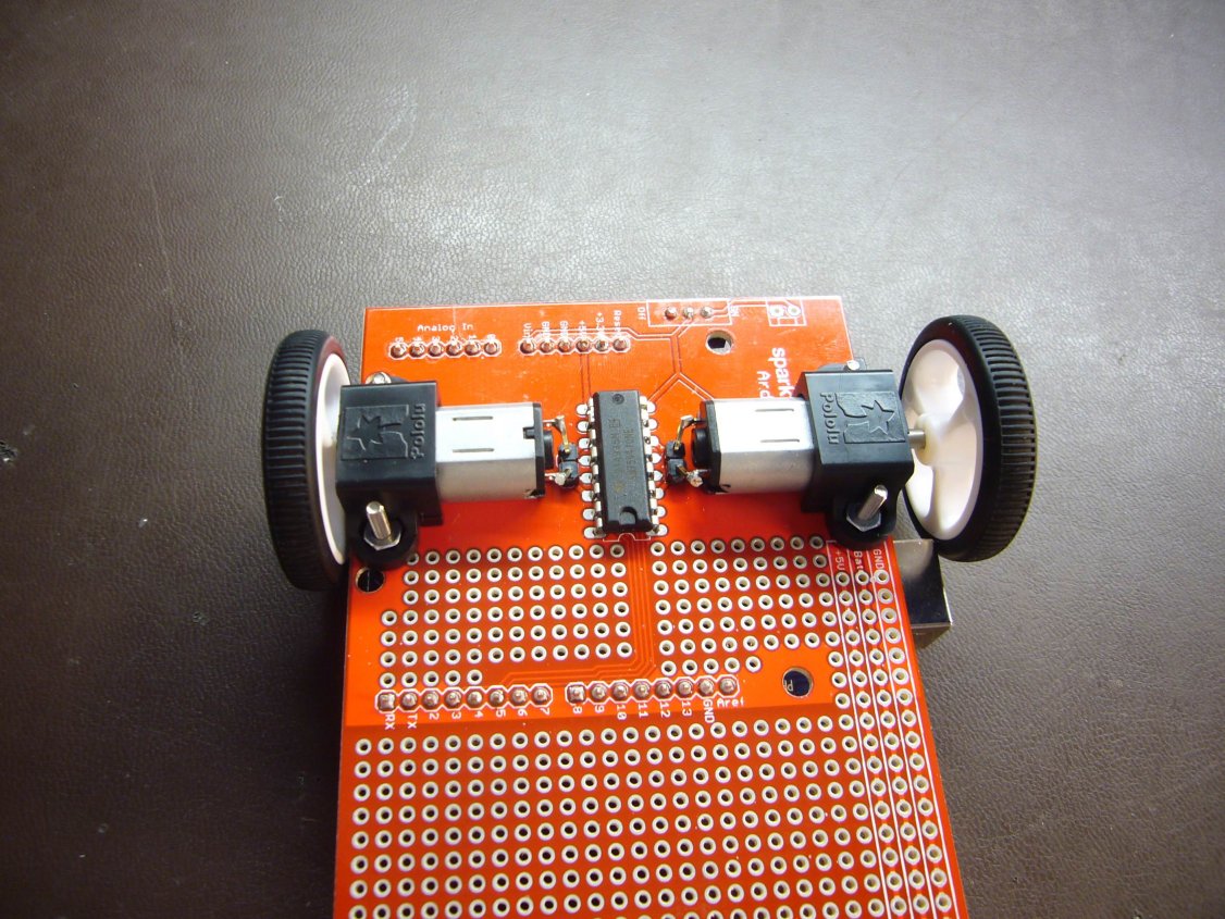
With a few tweaks, these headers fit nicely.
Next, we install the Arduino. For this build, I chose the USB version (a.k.a. Arduino Duemilanove). There is any number of methods to get this job done, this just happens to be what I did. There are two minor problems I?ve found with this configuration. I?ll address them as we go.
First, cut the male headers that you will need, 2 that are 1x8 and 2 that are 1x6, and install them into the female headers on the Arduino. The Arduino is to sit upside-down on the Ardubot board. The first problem with this configuration is that the programming header hits one of the mounting screws for one of the motors. To fix, clip off about 1/16? (or less) from the six pins that make up the header.
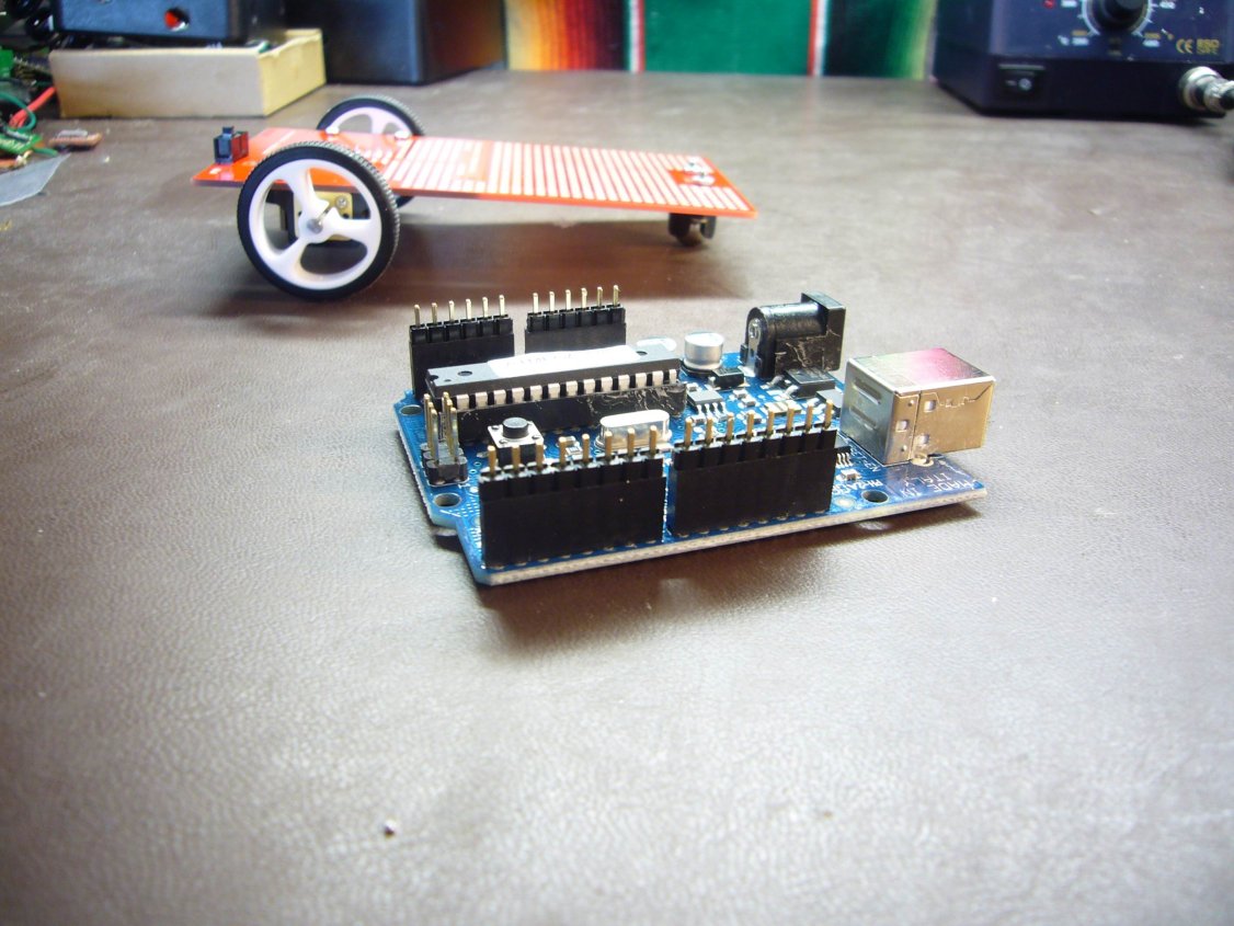
The Arduino posing with the Ardubot.
Then, install the Arduino onto the Ardubot PCB?and you should be seeing problem #2 right about now. The USB connector interferes with one of the wheels. The fix is to just slip the wheel out on the shaft a bit. This might make some people edgy, but this bot is unlikely to carry enough weight to cause a failure from this. Although I would encourage somebody to try, might be amusing.
In any case, adjust the fit to your liking and solder up the headers in the Ardubot board.
The Ardubot looking good.
Once you're there, flip it over and
admire your handiwork.

What this bot does is up to you!
Addendum: I forgot to mention the control inputs. Controlling the H-bridge is done with digital lines 3, 5, 6 and 9 on the Arduino. Lines 9 and 6 control the left side motor, lines 5 and 3 control the right side motor.
What now? The bot doesn't DO anything! Well, this is where you step in and play engineer. What do you want it to do? Surely, you didn't build it just to put it on a shelf and look pretty. So as an example, here's what I did.
The Annoyatron
Well, maybe it's not that annoying, but I did get a few gestures when some coworkers saw this thing wheel into their office and look at them.
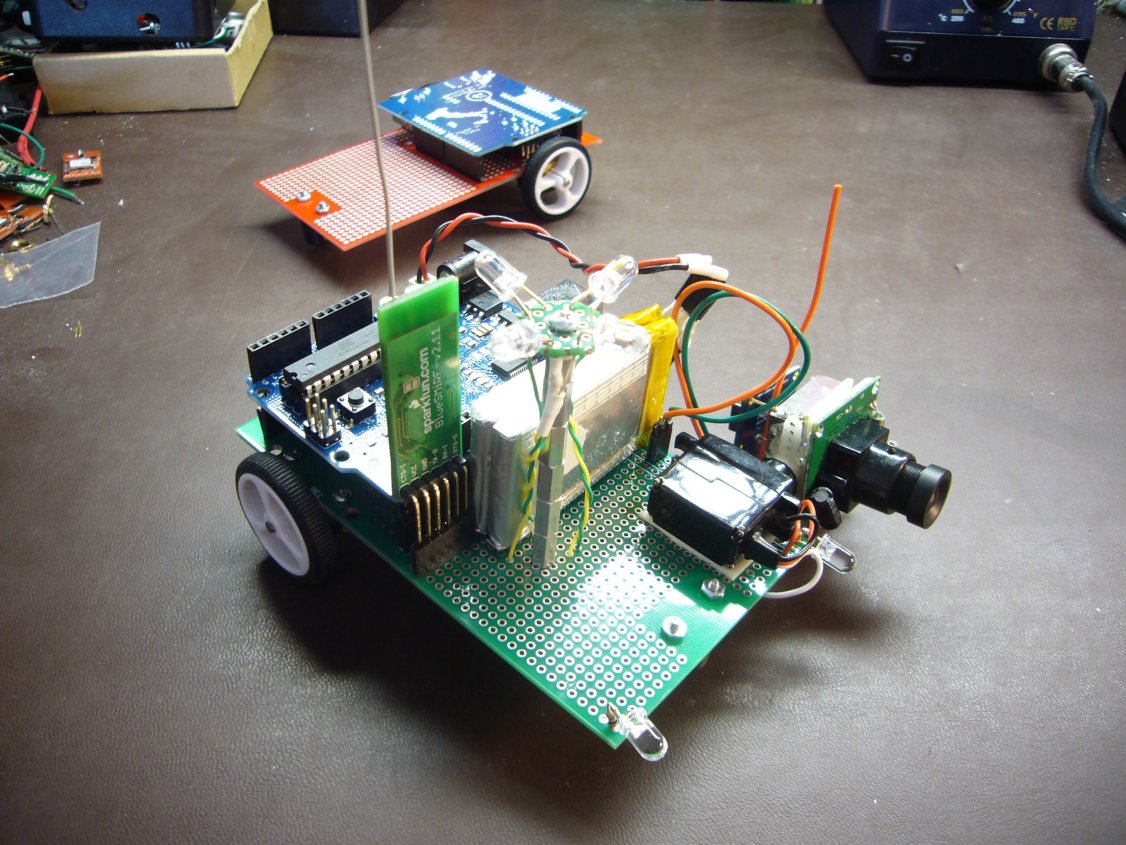
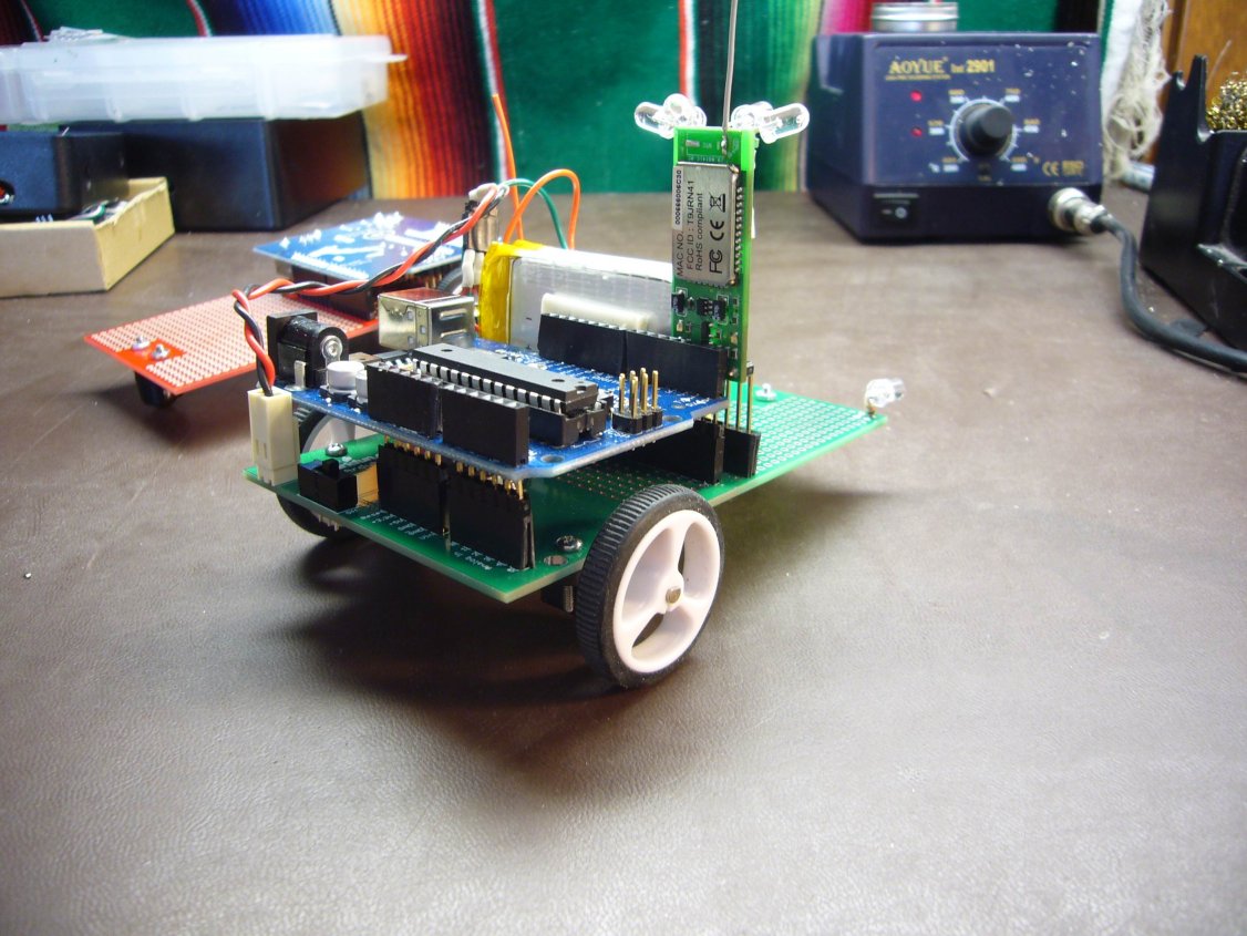
What are you lookin' at?
What you're looking at is an Ardubot that uses a BlueSMiRF for control input, and has a 2.4GHz video transmitter (it's the outdoor package that we sell, sku: WRL-09189, liberated from its' weatherproof casing). The idea is to go exploring from my desktop. It's got headlights (a pair of white LEDs on the front), and also an alternating blue and yellow LED pylon thingy sticking up out of the middle that flashes to hopefully keep people from ?accidentally? stepping on it. The camera is mounted on a servo that pans up and down, and it also has a microphone. The whole thing is powered by a 2-cell, series-wired 1100mAH lipo that I put together.
And while I'm thinking of it.... The battery header on the Ardubot PCB has been set up as one of our keyed battery connectors, but somehow I didn't have the foresight to put some kind of polarity indicators on it. I'll have to fix that in the silk for the next run, but for the time being here's a pic:
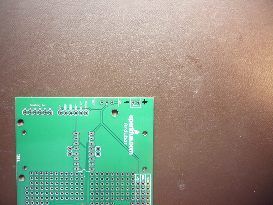
Not the most perfect silk screen, but it'll do.
The board provides busses for Vbat, 5V and ground, so powering anything extra is fairly simple. The 5V comes from the regulator on the Arduino, so bear that in mind as you add hardware. If you need more current, you can always add another 7805 or other 5V regulator. The Vbat bus runs from the main switch.
This was my original prototype, and I did it a little differently than the other one. In the first example I built everything with the PCB faced silk-down, and with this one I'm doing it silk-up. The main reason I wanted to do it that way was so that I could have the Arduino face up rather than face down. As added benefits, the USB connector and the programming header are no longer concerns.
Installing the Arduino this way isn't much of a trick, but I'll describe how I did it anyway.
Ardubot in all its glory.
It's actually pretty simple. First, cut two 1x8 and two 1x6 female and male headers. Put the female into the Ardubot PCB, soldering one pin of each so that they're still loose-ish and able to be moved somewhat. Then solder one pin of each male header (short side) to the bottom of a corresponding female header on the Arduino. It should be obvious, but in case it's not, all of these male headers need to be soldered to the same relative side of the female headers on the Arduino in order for the boards to line up right. Then you slide it all together and solder up all the unconnected pins. It probably doesn't matter as to the sequence, but I do the females on the Ardubot PCB first, then I go around and do the rest of the male headers to the bottom of the Arduino. Again, your mileage may vary.
As stated earlier, the camera is the new outdoor wireless set up that we sell, liberated from it's heavy case and mounted to a servo. The servo is powered from the 5V line, the camera is powered from Vbat.
Control is through a terminal. I go forward, backward, left, right, pan up and pan down with keyboard input.
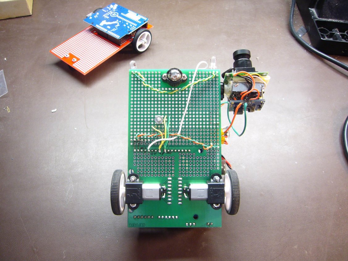
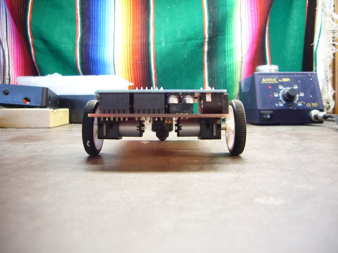
Just a quick shot of the undercarriage.
Performance
Honestly, so-so. I mean, it drives quite nicely, but I wish I had more time to work on it than I do. The biggest problem is the short range of the video. I can really get only a few offices away before it starts to break up really bad. I'd really like to get it on the wifi network with a web cam so people on-line could drive it around and go exploring. But for now, it's a cute toy.
Besides the shortcomings of the video, the platform is simple and robust, with lots of room for add-ons. I hope you all dig it.
Pete Dokter
SEXY!
I already built my ardubot but somehow I am bot sure if I messed up in the soldering because with the correct code I can control the left wheel but I can't control the right wheel because it turns on every time the right wheel turns on. Can this be happening because of a shortcut?
is there a way to control the speed of the motors with pwm using digital?
Could you please specify the parts that are in the plastic bags.
Excuse me if you specified them and I don't realize it.
Thanks.
is the switch necessary and what do i do if have to provide the motors with external power?
i built my ardubot but it always veers to one side when driving forward, any ideas or suggestions? Thanks
This would be great for a FEZ too
Is the suggested Annoyatron battery configuration chargeable by this:
http://www.sparkfun.com/commerce/product_info.php?products_id=8293?
Or each cell has to be charged independently?
This should so be available as a kit!
I'm using the Ardubot PCB as a robot itself, not as a robot platform, and I want to connect a Sharp distance sensor and a couple of bumpers and LEDs, how am I supposed to connect them to the Arduino pins, both digital and analog? Should I solder the wires directly to the short side of the male headers? Thanks!
Made a blogpost with some hardware and software details I was missing to program my Ardubot: http://blog.didierstevens.com/2009/08/23/quickpost-ardubot-programming/
Somebody should probably add the motor mounts to the parts list. I clicked through "The list", shoved stuff in my cart and didn't look back.
Now I need to wait and pay shipping for $5 worth of motor mounts :(
Somebody should definitely add the motor mounts to the parts list. Because some of us aren't smart enough to read the comments before making the same mistake.
Hey guys, sorry we didn't fix this sooner! I just finished a new rev of the PCB, and took a gander at these comments. The motor mounts are now part of the list above. Thanks for your feedback! Got any photos of your ardubots you'd like to share?
meh, now I can get those new wheels from pololu and see if they work better :)
So does this mean this is coming very soon? PCB not currently available for purchase :P did someone post this before they were supposed to?
Posted!
http://www.sparkfun.com/commerce/product_info.php?products_id=9207
Sorry. I'm behind.
Oh, you...
The tutorial is just active so I could get all the links and alignment right. The board should post in the next couple of days. There's so much going on around here lately that it's hard to get all of the timing right so that everything gets it's due coverage. Have patience; all of these things will come to pass.