
Danger Shield Kit Landing Page
The Danger Shield is an all-in-one demonstration-style board with as many sensors an inputs as we could fit. This guide will show you how to get up and running with your new shield.
First thing's first: crack open the packaging and survey your parts. You should have:
- 1x Danger Shield PCB
- 3x Slide Potentiometers - 10K
- 1x 7-Segment LED - Blue
- 1x 8-bit Shift Register - 74HC595
- 1x Temperature Sensor - TMP36
- 1x Miniature Photocell
- 1x Buzzer
- 1x Basic LED - Red
- 2x Basic LEDs - Yellow
- 1x Mini Push Button
- 3x Momentary Push Buttons - 12mm Square
- 11x Resistors - 330 Ohm
- 2x Resistors - 10K Ohm
- 1x Resistor 1M Ohm 1/6W
- 2x 8-pin Arduino Stackable Headers
- 2x 6-pin Arduino Stackable Headers
Once you've located all the parts, we can dive right in and start soldering. If you do not yet know how to solder, we recommend our Soldering 101 tutorial.
The best order in which to solder the Danger Shield parts is lowest-profile first, meaning the "shortest" parts. That way, when you flip the board over to solder, they're more likely to be held in by your work surface. In our case, this means starting with the resistors. There are three different resistor values in the kit, and the color codes for these resistors are as follows:
- 330 Ohm -- Orange-Orange-Brown
- 10k Ohm -- Brown-Black-Orange
- 1M Ohm -- Brown Black Green
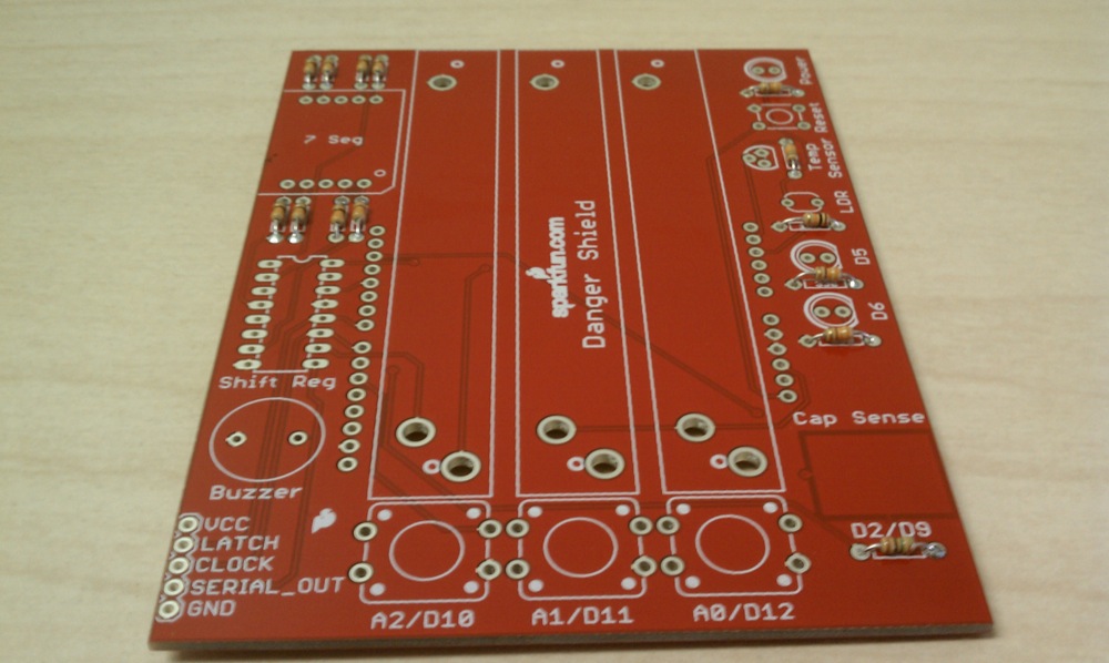
The resistor values are labeled on the PCB. Go ahead and solder in all the resistors in the indicated places. Bend the leads so that the resistor lies flat on the board, then spread the leads on the other side so that they are held in place. This allows you to insert and solder multiple resistors at a time. When you're finished your board should look like this:
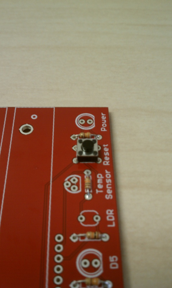
The next lowest-profile part is the button. It is non polar, so the orientation of the button doesn't matter. Go ahead and solder the button in it's spot in the top right corner. This is the button that will reset the Arduino when pressed. Your board should now look like this:
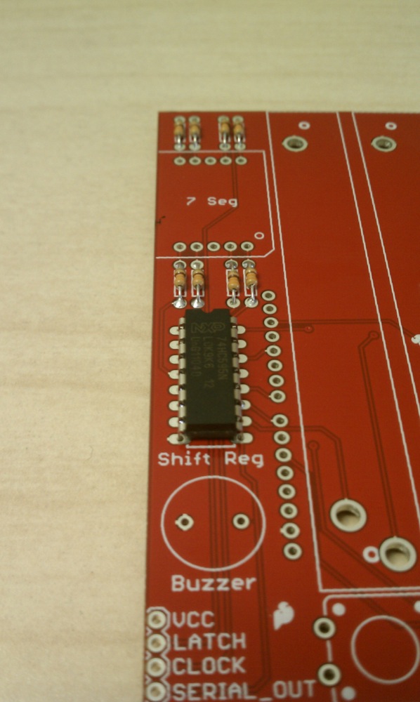
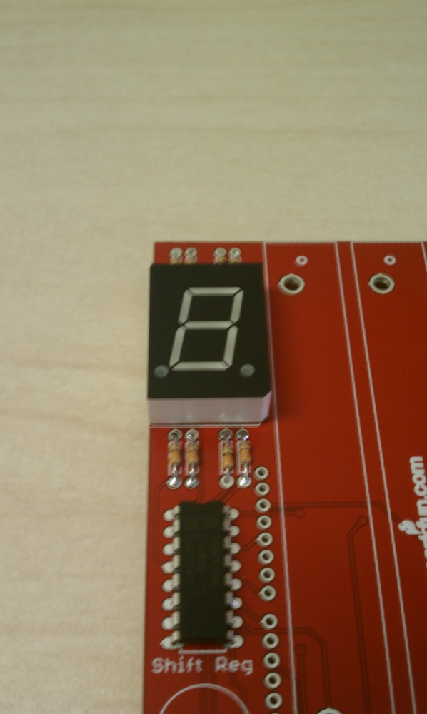
Next up is the shift register. This is the only chip included in the kit. This chip is what the Arduino communicates with to run the seven-segment display. The Arduino shifts in the values for the particular LEDs on the display, and the shift register toggles the appropriate pins. In order to solder this chip in correctly, be sure that the semi-circular notch on the chip matches up with the semi-circular notch on the PCB silk. Double check, because if the chip is soldered incorrectly it is very difficult to remove. You may find that you need to bend the pins of the chip in a bit so that it will snap into the board. When you're done, your board should look like this:
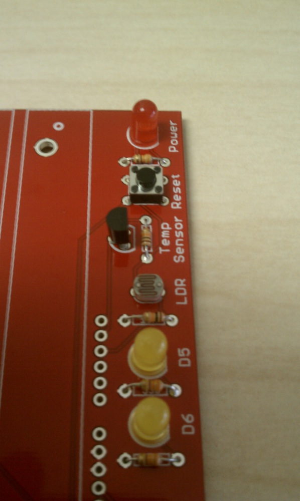
The next step is to solder in the three LEDs. Your kit includes two yellow and one red LED. The red LED goes in the top right corner, and is the power indicator LED. The yellow LEDs go along the right side of the board, and are controlled by digital pins D5 and D6 of the Arduino. The LEDs are polar, so they must be soldered with the correct orientation in order to work. Notice the base of the LED where the leads come out. Around that base there is a flat side to the resistor. This is reflected on the PCB silk. The flat side of the resistor should line up with the flat side of the silk. The other way to tell if you're placing the part correctly is that the shorter lead is inserted into the via closer to the flat part on the silk. When you have your LED's soldered, your board should look like this:
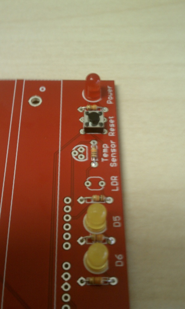
Next, we're going to solder in the temperature and light sensors. Both parts have silk on the upper-right section of the board indicating where they should be placed. You will have to bend out the center lead of the temp sensor in order to fit it into the board. The light sensor is not polar, so orientation doesn't matter. Once these parts are soldered in, your board should look like this:
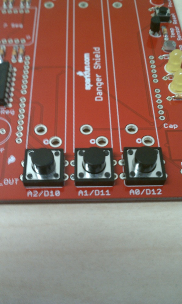
Next, we'll solder in the buttons along the bottom row. These parts are pretty self-explanatory. They're not polar, and orientation doesn't matter. Snap them into the front of the board and you can solder them all at once.
Next up is the seven-segment display. The display is really just a box of LEDs arranged and wired so that they can display numbers in what we like to call a digital-watch-style. This part is polar, so orientation matters. To place it correctly, notice the notch cut out of the bottom-right corner of the display. This is reflected in the silk on the left side of the board. Match the notch on the part to the notch on the board to place the part correctly.
The next part is the buzzer. Like the buttons, it is non polar, so orientation doesn't matter. If you're having trouble holding the buzzer flush while soldering it, you can scotch-tape it to the board to hold it in temporarily. Now your board should look like this:

The highest-profile parts in the kit are the sliders. Where they fit on the board should be obvious at this point. There is only one way to solder them into their places. So if you manage to place them incorrectly, please send us a picture. It's best to solder these in one at a time, and once again, you may want to tape them down while you're soldering to make sure they are flush to the board.
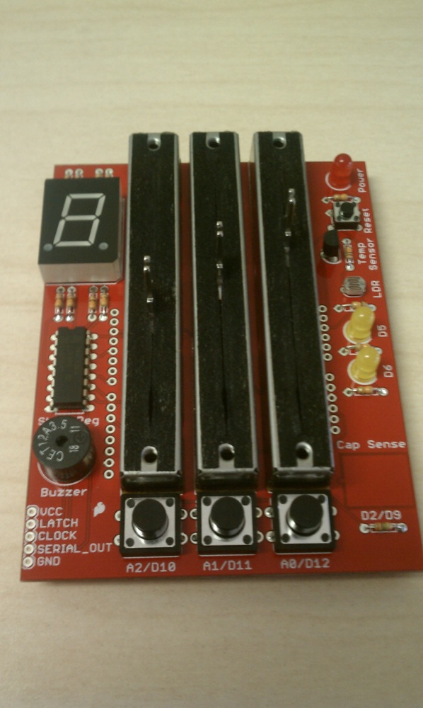
Last but not least, we have the headers. These are what connect your shield to your Arduino. This six-pin headers go on the right side of the sliders, and the eight pin headers on the left. Once these are soldered in, your shield is complete!
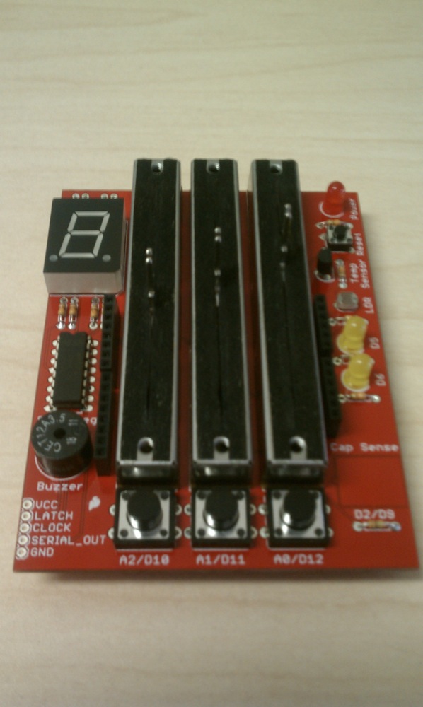
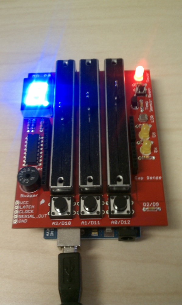
Now it's time for some programming. Before we actually load any code, connect your board to your Arduino and plug in the USB cable. All three LEDs should be lit and the seven-segment display should be displaying an "8".
For this example you will need two files: The Danger Shield example Arduino sketch, and the CapSense Arduino Library. Both can be downloaded here:
- Danger Shield example sketch with CapSense Library included (Arduino 023 and older)
- Danger Shield example sketch with CapSense Library included (Arduino 1.0.x compatible)
You can also check the Arduino CapSense page for updates to the library. This example uses V.04.
Unzip the folder, and place example sketch in your Arduino Sketchbook. Then, grab the CapSense library folder and place the folder in your Arduino->Libraries folder. The CapSense Library is required in order to use the capacitive sense pad on your shield, and documentation for it is held in the Arduino Playground.
With these files in place, you can now open your Arduino IDE, open the Danger Shield Example from your Sketchbook, and upload it to the board.
Once the code is uploaded, your shield should look the same as it did when you first powered it up, so let's see what the code is doing. Open a terminal in the Arduino IDE and make sure it is set to 9600 baud. At first, you should see this message
[first terminal]
This is the output for the example code. This code will sequentially test each device on the Danger Shield. To move on to the next device, press the button on the bottom left marked D10. The order of the tests is as follows:
- Button 1 Test -- The Danger Shield will wait for you to press the button marked A2 to move on to the next device
- Slider Test -- This test prints the voltages detected by the three sliders. Move the sliders up and down to see the values change
- Buzzer Test -- The buzzer should be going off at this point
- CapSense Test -- The numbers whizzing by represent the capacitance detected on the CapSense pad. Press the pad with your fingers to see the numbers jump to the hundreds.
- Temp Sensor Test -- This is the voltage coming from the test sensor. Cover the sensor with your fingers to see the value slowly change as the temperature increases.
- Light Sensor Test -- This tests the voltage on the light sensor. Cover the sensor with your hand to see the value go down, indicating less light.
- Button 2 & 3 Test -- This tests the second and third buttons (labeled D11 and D12) as well as the two yellow LEDs. Press the D11 button to see the D6 LED turn off, and press D12 to see the D5 LED turn off.
- Seven Segment Display Test -- Once in this mode, the program will increase the number on the seven-segment display from 0-9 until the shield is reset. Hit the reset button to start over.
That's the basics of your Danger Shield. To see how each device is being controlled/read, be sure to read the comments in the code. Each device has its own section with an explanation of its usage. Have fun!
BTW, I even took some photos of the process. I could post them somewhere (where?, I don't know) if others would find it useful...
I just bought one and the problem with the TMP36 is still there. I found an easy fix though. First, just omit the 10k resistor right next to the sensor. Install the TMP36 the same way as specified (flat side towards the non-existent resistor.) But, with pin 1 (the leftmost pin viewed from the bottom with the flat side up), just run the pin through the board and then to the "hot" side of the (nonexistent) resistor. That's the left side as viewed from the bottom with the temp sensor up. Solder it. This will ensure that pin 1 is connected to +5V, pin 2 is connected to A4, and pin 3 to ground, which is as it should be for the new chip. It passes the test in the example sketch.
Hi, I bought Danger Kit and assembled it in a couple of hours.
Now I would like to use Danger Shield + Uno it to control a program running on Rainbowduino. I have never connected two Arduinos before, and I am a bit stuck:
Rainbowduino has two sets of 8 pins presumable for this purpose: one is male, one is female. The connections are:
It also has holes for the following pins: D3, D2, A0, A1, A2, A3, A6, A7.
I want to be able to send data from the controllers on Danger Shield, so that I can control a game on the LED matrix.
I tried sending PWM voltage and using analog inputs on Rainbowduino (and another board) – even though I was reading correct voltage, analog inputs were going off crazy between 0 and 1023 switching as I was sending AC instead of DC. I wasn't sure whether I was supposed to connect the two duinos via a ground, and/or 5V?
How do I use the SDA/SCL or TXD/RXD on Rainbowduino, and what do I connect it to on my Danger Shield/Uno? Everything seems already taken :(
Thanks!
I think the board has been updated. I just assembled mine according to the above instructions and everything works fine. The board is marked v1.7
My kit came with 2 100 nf (104) capacitors which are not mentioned above. There are 2 unmarked pairs of holes in the board; one next to the temperature sensor and another just above the shift register. Should I install the capacitors?
Assembly went smoothly but since the above is in order by profile height, the headers should be installed before the buzzer and potentiometers, it took a bit of fiddling around to get them to stay straight for soldering.
Just finished building the danger shield and downloaded the files from this page. I uploaded the example sketch and added the h and cpp files into the IDE and I am getting an error: 'CapSense does not name a type'.
I've searched online trying to find the reason for the problem but have not had any luck.
Any help would be appreciated...
PLEASE READ THE INFO IN THIS THREAD ABOVE ABOUT THE ISSUE WITH THE TMP36 SENSOR
Thanks to the member who posted yesterday! I was wondering why the temp TMP36 sensor was not operating correctly as I soldered it in tonight. Your comment helped me to fix it! Although I only saw this update after I soldered the two parts (temp sensor and resistor) in.
I removed the resistor and took one of the leads that was trimmed during soldering and soldered it from the left resistor terminal to the PIN 1/left sensor terminal. I did the bare wire pass-through into the empty resistor terminal and crimped a small loop of the trimmed lead around the protruding sensor lead that remained soldered.
I was able to get the temperature readout to update higher by heavy breathing on the sensor (I tested before the final solder of the bridge wire). :) Its reading moved up with increasing temperature...
Incidentally mine from that dealer was also missing a resistor. Which I should have found from the beginning, closed it up and brought it back... Instead I found the missing value and installed it from a collection.
For mine which I bought from a dealer, I bought a socket for the shift register. Further releases of this excellent example of what can happen with an excellent design source and a mechanism to build them, should include these sixteen pin sockets for the shift register.
Over on the old-school version page (http://www.sparkfun.com/products/10570) a comment says there needs to be some changes to the board for the TMP36 to operate properly (remove resistor, add capacitor, etc.)
Have these been updated in the board? assuming retail and 10570 are same board.