
Breadboard Power Supply Kit 5V/3.3V Quickstart Guide
Overview:
The Breadboard Power Supply Kit allows your breadboard projects to easily access a selectable voltage regulated to either 3.3Volts or 5Volts. It receives its power through a DC wall wart like this one. Any stripped +/- DC supply can also be connected instead of the barrel connector if desired. This guide will help with everything you need to get started with the Breadboard Power Supply.
Breadboard Power Supply Kit 5V/3.3V
Requirements:
This kit comes as a bag of parts and requires assembly with the use of a soldering iron and requires you to solder all the parts onto the printed circuit board yourself. You will need a few tools to be able to do this. Following is a list of recommended tools and assembly parts:
Tools:
- Soldering Iron
- Solder
- Wire cutters
- Solder wick (optional - in case of mistakes)
- Multimeter (optional - for quick test after assembly)
The Kit Contains:
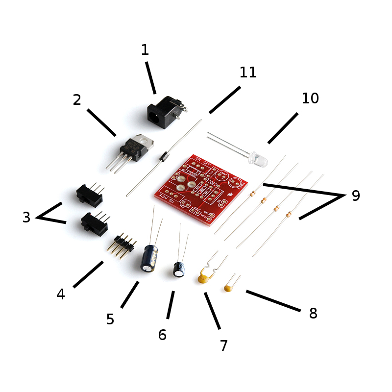
- DC Barrel Connector
- Voltage Regulator (LM317 1.5A max current)
- 2pcs SPDT Slide Switch
- 4pcs 0.1" Header Pins
- 100uF 25V Capacitor
- 10uF 25V Capacitor
- PTC resettable fuse
- 0.1uF 50V Capacitor
- Resistors: 330 Ohm 1/6W - Orange, Orange, Brown X2
- 390 Ohm 1/6W - Orange, White, Brown X1
- 240 Ohm Resistor 1/6W - Red, Yellow, Brown X1
- Red Super-bright LED
- 1N4004 Reverse Protection Diode
- Bare PCB
Use the links above and the image below to identify any parts you are unfamiliar with. The numbers in the list above correlate with the numbers in both the images below to help you with assembly. Missing any parts? Drop our customer service team an email. We'll get them out to you as soon as possible.
How to use it:
Assembly
With some beginning experience in soldering, assembly should be rather straightforward. If this is your first time soldering, we recommend taking a look at our soldering tutorials.
All the parts are to be soldered to the top of the board (the side with the silkscreen writing) with the exception of the headers. The .1" headers are mounted on the bottom of the PCB for simple insertion into a breadboard. We will assemble the kit in the order listed above. However, take note that the parts can technically be soldered in any order, and often times, the easiest method is to start with the smaller components on the top (resistors, diode, small caps, etc.), then moving on to the larger components (voltage regulator, barrel jack, etc.) For this board though, it's not a huge concern because there is enough working room regardless of the order you choose. The whole process is estimated to take 30 minutes but varies based on your soldering skill level. Here is a photo of the PCB for reference:
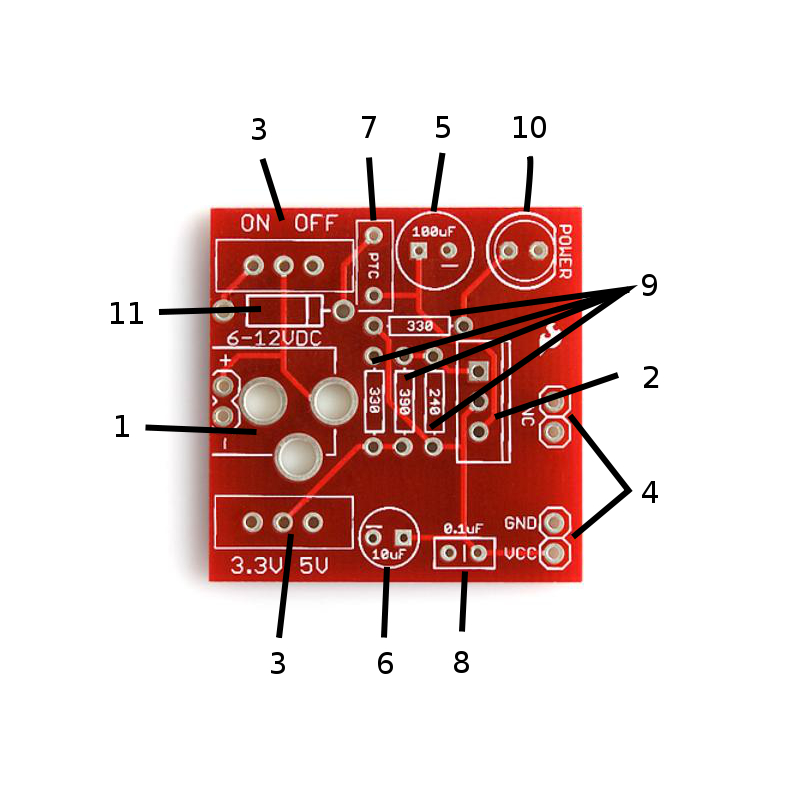
Keep in mind the numbers of each part in the part list above matches the two images labeled with numbers as well as the instructions below. This should allow you to easily figure out what item needs to be soldered where.
- Place the DC barrel jack so that its 3 pins line up with those on the board.
- Align the voltage regulator's back metal plate with the side of the silk screen that has the extra white strip. It's the right side in the picture of the PCB above.
- Solder in a switch into both positions, orientation does not matter as long as all 3 pins are soldered in.
- Break the header into two pieces of two pins. Place the shorter side of each header into the holes from the bottom side of the board. Reference the very first photo of this tutorial if you are confused. Solder the header in to imitate that photo. You want the long side of the pins facing downward so they can be plugged into a breadboard.
- Place the large 100uF capacitor into its slot. Careful, as it is polarized, meaning it will only work if it's placed in the right direction. Align the minus sign of the capacitor with the minus sign on the silkscreen.
- Place the slightly smaller 10uF capacitor into its slot. Just as we did in the last step, make sure it's in the right direction by matching the minus signs.
- Put the PTC resettable fuse into its slot. Orientation does not matter.
- Place the .1uF capacitor in its slot. Since this is a ceramic capacitor, orientation does not matter.
- There are four spots for resistors on the printed circuit board. You can see that each one is labeled with a number. Those numbers are 330, 390, and 240. These numbers refer to the amount of resistance of each resistor measured in Ohms. The resistors are color coded and the colored stripes represent different numbers. Place the two resistors coded 'orange orange brown' into the slots marked '330'. Place the resistor marked with 'orange white brown' into the slot marked '390'. Last, place the resistor marked with 'red yellow brown' into the slot marked '240'. Orientation doesn't matter with resistors. For more on color coding, refer to this wiki.
- Place the LED in its slot. Orientation does matter. Match the side with the flat edge and shorter leg, with the silkscreen side that also has the flat edge.
- Place the diode into its slot. Orientation does matter. Match the stripe on one end of the diode with the same stripe on the silkscreen of the PCB.
Use wire cutters to snip any extra leads and if you accidentally soldered something into the wrong place, use solder wick to get rid of the solder, replace the component, and solder again. If you've never done something like that before, it's worth it to check out our soldering tutorials beforehand.
How To Use It:
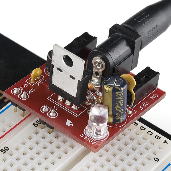
After it's all soldered, it's time to plug it into the breadboard. Line up the the VCC and GND header pins with the power rails on the breadboard. The other two header pins should fit into the breadboard as well as shown in the first photo. These two extra pins are only there for physical support and don't have any electrical connection on the PCB. Reference the photograph below if needed.
All that's left is connecting the wall wart to the barrel jack, selecting which voltage you want via one of the switches and using the other switch to turn it on. The red LED should light up. Careful, it's bright. Double check each voltage setting with a multimeter to make sure the proper voltage is being applied to the breadboard (3.3V or 5V depending on the switch settings).
Resources:
Conclusion:
Well, now that you have the power, it's time to build some circuits! Always feel free to share your projects with us! If you run into any trouble along the way, feel free to contact SparkFun Technical Support at techsupport@sparkfun.com.
Protip: Do NOT attempt to build this kit over yellow shag carpet! (Or at least don't drop the 0.1uF cap on the carpet if you do...)
And I fully agree with udawatabhimanyu4, your breadboard has TWO sides you can put this on. If it is not proper the first time you try, remove it, move your board in a 180 degree (half circle) motion and it will be then.
This is not difficult people
Hahaha!
You could obviously rotate the breadboard full 180 degree to correct the Color labels.
The blurb above says that voltage regulator is rated to a max of 1.5A but if you click through to the blurb for the polyfuse it says it blows at 500mA. So presumably you'd need a different polyfuse to use this to provide, say, 1A for a Raspberry Pi?
I just built this over an oriental rug and dropped the diode. Luckily I have a bright LED light and found it, lol. I built an astable multivibrator and this pwoers it at 5V. I was enjoying watching the LED's blink on and off and then something shorted and poof out came the smoke. I changed the caps and the transistors and got it working again and then I shorted an LED and havent been able to get it going again because the single sided proto board is cheap and cant handle heat and now I have opens to find. Through all that this power supply is the one part that hasnt failed. It was very easy to build and I will need more than one for multiple projects.
What are the NC pins used for?
Does anyone know what the NC pins are used for?
According to a comment in the product page - and I'd have to agree with them - it's probably to provide some mechanical stability. I'll add that it also offsets the solder joints of the PTH parts away from the breadboard surface, in the off chance one should make contact. I don't know why they're not shifted over a bit further to make it a bit more stable still, but I'm sure they had a good reason for that decision :)
NC is standard PCB labeling for No Connection. And I agree these are there to allow you to hook them into the breadboard for added stability.
Anyone know the max input voltage?
The datasheet says the max Vin - Vout = 37V, so I'd keep the input below 40V. However, the larger the input voltage, the hotter the LM317 is going to get. So use a lower voltage input if you can, somewhere between 6-15V would be best.
Since the raw input voltage is applied to C1, which is rated at 25V, you should keep the input voltage below this. Or replace C1 with a higher-voltage capacitor.
OK, this was my first project and I really enjoyed building it! I could use some help in troubleshooting though. I have triple checked all the components are in the right place and polarity, my solder joints are as you would expect from a rookie, but no bridges noticeable. When I power it up, I get just about 3V out regardless of the output switch setting.
Anybody care to recommend a starting point/component? I have spent a lifetime doing software so debugging electronics is pretty new to me.
so far I do see 5.25 V at the input connector, not sure where to go next. The led does come on, the voltage at the output select switch is around 1vdc regardless of the sw position but I doubt that matters.
Sorry for the rookie question, but thanks for any help.
I found the same thing with an input of 5.25 V. I switched to 9 V and it worked.
you may have a faulty voltage switch like I encountered
The input voltage needs to be greater than 6V for the regulator to properly output 5V. This is because of the forward voltage drop of the inline diode and slight drop of the regulator.
I fully agree with Member #283768, photo is misleading and should be corrected to show the GND pin connected to the red labeled track and VCC connected to the blue labeled track.
You both are right, (Muthanna, and #283768). The simplest remedy - remove the board, and insert it at the opposite end of the breadboard - Just be certain to use the "other" power rail. Bottom right of the picture shows the 'Blue' band, and the 'Red' is cropped out (Blue, and Red are in the same layout, at top Left). Hence, removing the power supply, flipping the breadboard 180 degrees, then re-inserting the power supply means it is properly aligned.
Thanks for the great tutorial with excellent, clear photos. I did notice something that could be a problem for some builders. In the photos the power supply is shown with the ground pin connected to the red rail on the breadboard and the Vcc connected to the blue rail. On the breadboards that I've seen, the red line is usually marked as +ve and blue is the -ve or ground. I can see this causing confusion and perhaps enabling the release of smoke from the powered circuit :)