
Elevator TARDIS
We here at SparkFun have been known to use our products to play pranks on each other from time to time, and we're always on the lookout for ways to make life at the office more Fun™. While riding our elevator one day, it occurred to me that the ride could be made more interesting... but how? Then I realized - not how, but Who!

The Doctor to the rescue
If you’re not already a fan of the British science-fiction show Doctor Who, this project won’t make much sense to you. For the rest of you, the signature sound of the Doctor’s time and space machine, the TARDIS, is instantly recognizable. Doctor Who was first broadcast in 1963 (it is the longest-running science fiction TV show in history), and from the beginning has made clever use of low-budget but creative special effects. The cyclic, ethereal grinding sound of the TARDIS was originally created by BBC sound technician Brian Hodgson by dragging a set of house keys along the strings of a piano, and electronically processing the result. (Yes, I’m a giant nerd for knowing that.) The sound of the TARDIS is known instantly to generations of fans, which provides a perfect opportunity to bring it into existence in our humble lift.
Goals
- Play the TARDIS sound in the elevator while it’s going up or down (blinking blue light a bonus).
- ???
- Profit!
Note that the core of this project (play a sound when a sensor is activated) is applicable to all sorts of areas (Halloween, art installations, scaring your little brother, Burning Man, etc.), so read this with an eye to applications you'd like to see.
Recon
My first thought was to hack straight into the elevator’s up and down buttons, but I quickly came to my senses. Building managers do NOT want you messing with critical infrastructure (for good reason), and I personally don’t want to get on the bad side of anyone who gets stuck in an elevator because of me. (Around here the winner has been known to choose the loser’s tattoo.)
However, it occurred to me that it might be possible to make a completely self-contained unit, discreetly placed above the elevator’s drop-ceiling, that could detect when the elevator starts moving all by itself. How? By using an accelerometer.
An accelerometer measures, logically enough, acceleration. This is different from velocity - while a car (or an elevator) is accelerating from stopped to cruising speed, the accelerometer will read > 0. But once the car (or elevator) has reached cruising speed and the velocity is constant, the accelerometer will read 0. When you decelerate, the opposite happens - the accelerometer will read < 0, until the car (or elevator) has stopped, at which point the accelerometer will again read 0.
To see what kind of numbers we were dealing with, I hooked up an Arduino, an ADXL345 and an Openlog. (Tip: the Openlog is a great tool for early development work like this - it stores all the data you can generate, making it easy to analyze later and see what you can do with it). I took a quick trip up and down in the elevator, popped out the SD card, loaded the data into a spreadsheet, and made a quick graph:
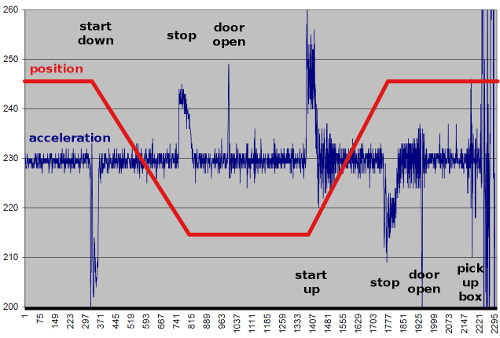
In the above graph, the approximate elevator position is the red line, and the Z-axis data out of the accelerometer is the noisy blue line. You can see spikes in the accelerometer data when the elevator starts and stops, and at other times the readings hang around 230 (1g). These spikes aren't huge - the peaks aren’t far outside the 1g noise - but they look clear enough to pick up with a little coding. Let’s try it!
Shopping list
Now’s the time to divide the project into subsystems: modules we can connect together to do all the things we want.
The main requirement is to play back the TARDIS sound. SparkFun carries several products that could do this, but we’ll balance cost and ease of development and go with a combination of 3.3V Arduino Pro and MP3 Shield. We’ll use the Arduino to read the accelerometer and decide when to play the sound, and use the MP3 shield to play the TARDIS sound directly off an microSD card. We’ll also grab two sets of Stackable Headers to connect the boards together.
SparkFun carries a number of accelerometers that would work in this application. I went with an ADXL345 for its ease of use and extra features like threshold interrupts that we could potentially use to wake everything up when the elevator’s moving.
The MP3 Shield has line-level audio outputs. To produce a suitably loud noise, we’ll need an amplifier and a speaker. The amplifier is a prototype of a board we’ll soon be carrying. The speaker, a cheap desktop-computer model, came from our recycling bin.
We’ll need a battery. The reason I chose a 3.3V Arduino Pro is that they run very nicely on our 3.7V LiPo batteries. I chose the 6Ah battery for maximum life, but it's admittedly expensive. You could certainly get away with a smaller one depending on your lifetime requirements (see also the "enhancements" section below for battery-life tips).
Finally, it occurred to me that along with the sound, it would be nice to simulate the blinking blue light on top of the TARDIS. Throw in a couple of ultra-bright blue LEDs and resistors*. These LEDs use more power (80mA x 2) than an Arduino I/O pin can provide (20mA), so we’ll use one of Nate’s little MOSFET boards to drive them. We only need one board to drive pretty much as many LEDs as we like - up to 4 Amps worth.
* Since we'll be powering the LEDs directly off the battery (to avoid overtaxing the 3.3V regulator on the Arduino Pro board), we should think a little bit about the maximum voltage the LEDs will see, and choose the current-limiting resistor accordingly. The flat part of a LiPo battery's discharge curve is around 3.7V, but the voltage could be as high as 4.2V when it's fully charged. To prevent burning out the LEDs, we'll use the worst-case numbers: 4.2V from the fully-charged battery, and from the LED product page, Vf = 3.0V and If = 80mA . Plug these into the handy LED resistor calculator of your choice, and the recommendation is 18 Ohms. We'll use one resistor per LED (so we can use lower-power resistors), and power the LEDs in parallel, but you can run the numbers for other resistor configurations if you wish.
Apart from some headers, jumper wires and traditional red cardboard box, we’re ready to put everything together! Thanks to the folks in IT, here's a handy shopping list:
Hardware
Assembly is straightforward. Solder the 6 and 8-pin headers to the Arduino Pro and the MP3 Shield, and stack them together. The battery plugs into the JST connector on the Pro. The rest of the circuitry connects the various boards. The following schematic shows the connections (click for a larger view):

I threw everything into one of our famous red boxes, but you can do whatever works best for your project. The only critical part is to mount the accelerometer board securely and horizontally (Z-axis pointing down), so that it will properly pick up the motion of the elevator.
Software
As you’re probably aware, the great thing about the Arduino is the vast amount of example code available. On the MP3 Shield product page is a complete playback example sketch, and a little Googling turned up this page with ADXL345 interface code. Combining these two pieces of code resulted in very close to the final product (thank you, internet!)
It’s usually not difficult to mash several pieces of code together. You only get one setup() and one loop() per sketch, so merge everything into one set of functions. Make sure there aren't any pin conflicts, and reallocate one of the pins if there is.
Here's the whole sketch (or you can download it here):
// Elevator TARDIS!
// Mike Grusin, SparkFun Electronics, 10/2011

// Samples an attached ADXL345 accelerometer,
// Waits for an acceleration indicating that the elevator has started moving
// then use the MP3 Shield to play the TARDIS sound for LOLs.

// Based on the MP3 Shield example code by Nathan Seidle,
// and ADXL345 code from http://codeyoung.blogspot.com/2009/11/adxl345-accelerometer-breakout-board.html

// NOTE: be sure to follow the below instructions on installing the sdfatlib to allow the MP3 Shield to function!

/*MP3 Player Shield example code
 4-28-2011
 Spark Fun Electronics 2011
 Nathan Seidle

 This code is public domain but you buy me a beer if you use this and we meet someday (Beerware license).

 This example code plays a MP3 from the SD card called 'track001.mp3'. The theory is that you can load a
 microSD card up with a bunch of MP3s and then play a given 'track' depending on some sort of input such
 as which pin is pulled low.

 It relies on the sdfatlib from Bill Greiman:
 http://code.google.com/p/sdfatlib/
 You will need to download and install his library. To compile, you MUST change Sd2PinMap.h of the SDfatlib!
 The default SS_PIN = 10;. You must change this line under the ATmega328/Arduino area of code to
 uint8_t const SS_PIN = 9;. This will cause the sdfatlib to use pin 9 as the 'chip select' for the
 microSD card on pin 9 of the Arduino so that the layout of the shield works.

 Attach the shield to an Arduino. Load code (after editing Sd2PinMap.h) then open the terminal at 57600bps. This
 example shows that it takes ~30ms to load up the VS1053 buffer. We can then do whatever we want for ~100ms
 before we need to return to filling the buffer (for another 30ms).

 This code is heavily based on the example code I wrote to control the MP3 shield found here:
 http://www.sparkfun.com/products/9736
 This example code extends the previous example by reading the MP3 from an SD card and file rather than from internal
 memory of the ATmega. Because the current MP3 shield does not have a microSD socket, you will need to add the microSD
 shield to your Arduino stack.

 The main gotcha from all of this is that you have to make sure your CS pins for each device on an SPI bus is carefully
 declared. For the SS pin (aka CS) on the SD FAT libaray, you need to correctly set it within Sd2PinMap.h. The default
 pin in Sd2PinMap.h is 10. If you're using the SparkFun microSD shield with the SparkFun MP3 shield, the SD CS pin
 is pin 9.

 Four pins are needed to control the VS1503:
 DREQ
 CS
 DCS
 Reset (optional but good to have access to)
 Plus the SPI bus

 Only the SPI bus pins and another CS pin are needed to control the microSD card.

 What surprised me is the fact that with a normal MP3 we can do other things for up to 100ms while the MP3 IC crunches
 through it's fairly large buffer of 2048 bytes. As long as you keep your sensor checks or serial reporting to under
 100ms and leave ~30ms to then replenish the MP3 buffer, you can do quite a lot while the MP3 is playing glitch free.
*/

#include <Wire.h> // I2C library for ADXL345 interface

#define ADXL345_ADDRESS 0x53 // ADXL345 device address
byte ADXL345_buff[6]; // 6 bytes buffer for saving data read from the device

#include <SPI.h> // SPI for MP3 chip and SD card

#include <SdFat.h> // SdFat Libraries
#include <SdFatUtil.h>

//Create the variables to be used by SdFat Library
Sd2Card card;
SdVolume volume;
SdFile root;
SdFile track;

//This is the name of the file on the microSD card you would like to play
//Stick with normal 8.3 nomeclature. All lower-case works well.
//Note: you must name the tracks on the SD card with 001, 002, 003, etc.
//For example, the code is expecting to play 'track002.mp3', not track2.mp3.
char trackName[] = "track001.mp3";
int trackNumber = 1;

char errorMsg[100]; //This is a generic array used for sprintf of error messages

#define TRUE  0
#define FALSE  1

//MP3 Player Shield pin mapping. See the schematic
#define MP3_XCS 6 //Control Chip Select Pin (for accessing SPI Control/Status registers)
#define MP3_XDCS 7 //Data Chip Select / BSYNC Pin
#define MP3_DREQ 2 //Data Request Pin: Player asks for more data
#define MP3_RESET 8 //Reset is active low
//Remember you have to edit the Sd2PinMap.h of the sdfatlib library to correct control the SD card.

#define AMP 5 // audio amplifier shutdown pin
#define BLUELIGHT 10 // TARDIS blue light output (use a PWM-capable pin)

//VS10xx SCI Registers
#define SCI_MODE 0x00
#define SCI_STATUS 0x01
#define SCI_BASS 0x02
#define SCI_CLOCKF 0x03
#define SCI_DECODE_TIME 0x04
#define SCI_AUDATA 0x05
#define SCI_WRAM 0x06
#define SCI_WRAMADDR 0x07
#define SCI_HDAT0 0x08
#define SCI_HDAT1 0x09
#define SCI_AIADDR 0x0A
#define SCI_VOL 0x0B
#define SCI_AICTRL0 0x0C
#define SCI_AICTRL1 0x0D
#define SCI_AICTRL2 0x0E
#define SCI_AICTRL3 0x0F

// TARDIS lighting effects
float bluelight;
float blueenvelope;
const float TWOPI = 6.283185307179586476925286766559;

void setup()
{
  pinMode(MP3_DREQ, INPUT);
  pinMode(MP3_XCS, OUTPUT);
  pinMode(MP3_XDCS, OUTPUT);
  pinMode(MP3_RESET, OUTPUT);

  pinMode(AMP,OUTPUT); // amp control
  digitalWrite(AMP,LOW); // turn amp off

  pinMode(BLUELIGHT,OUTPUT); // blue light

  MP3disable(); // turn MP3 chip off

  Serial.begin(57600); //Use serial for debugging
  Serial.println("MP3 Testing");

  //Setup SD card interface
  pinMode(10, OUTPUT);       //Pin 10 must be set as an output for the SD communication to work.
  if (!card.init(SPI_FULL_SPEED))  Serial.println("Error: Card init"); //Initialize the SD card and configure the I/O pins.
  if (!volume.init(&card)) Serial.println("Error: Volume ini"); //Initialize a volume on the SD card.
  if (!root.openRoot(&volume)) Serial.println("Error: Opening root"); //Open the root directory in the volume.

  //We have no need to setup SPI for VS1053 because this has already been done by the SDfatlib

  //ADXL345 setup
  Wire.begin();        // join i2c bus (address optional for master)

  //Initialize the ADXL345
  I2Cwrite(ADXL345_ADDRESS, 0x2D, 0);
  I2Cwrite(ADXL345_ADDRESS, 0x2D, 16);
  I2Cwrite(ADXL345_ADDRESS, 0x2D, 8);
}

void loop()
{
  int x, y, z;
  static int count; // static means that this variable will be preserved each time we loop

  // read the current acceleration from the ADXL345:
  I2Cread(ADXL345_ADDRESS, 0x32, 6, ADXL345_buff);
  //each axis reading is 10 bits in two bytes. combine these into one int.
  x = (((int)ADXL345_buff[1]) << 8) | ADXL345_buff[0];
  y = (((int)ADXL345_buff[3])<< 8) | ADXL345_buff[2];
  z = (((int)ADXL345_buff[5]) << 8) | ADXL345_buff[4];

  // from experimentation, we know that 1g is about 230.
  // We'll look for values a little outside that range.
  // We also want to look for a sustained acceleration, not single spikes,
  // so we'll wait until we have 10 values in a row that fall outside that range.

  if ((z > 238) || (z < 220))
    count++;
  else
    count = 0;

  if (count > 10) // bingo! bring on the noise! bring on the funk!
  {
    // reset the light values to 0
    bluelight = 0.0;
    blueenvelope = 0.0;

    // turn on the MP3 chip
    MP3enable();

    // turn on the amplifier
    digitalWrite(AMP,HIGH);

    // start playing the sound
    sprintf(trackName, "TARDIS.MP3");
    playMP3(trackName);

    // done playing, turn off the amplifier
    digitalWrite(AMP,LOW);

    // turn off the MP3 chip
    MP3disable();

    // if the light is still some level of "on", fade it to off
    while (bluelight > 0)
    {
      Mp3whilePlaying();
      delay(10);
    }
  }
  // loop delay for 100Hz ADXL readings
  delay(10);
}


void MP3disable()
// hold the MP3 chip in reset, lowers power consumption
{
  digitalWrite(MP3_XCS, HIGH); //Deselect Control
  digitalWrite(MP3_XDCS, HIGH); //Deselect Data
  digitalWrite(MP3_RESET, LOW); //Put VS1053 into hardware reset
}


void MP3enable()
// unreset the MP3 chip and initialize the registers
{
  //From page 12 of datasheet, max SCI reads are CLKI/7. Input clock is 12.288MHz.
  //Internal clock multiplier is 1.0x after power up.
  //Therefore, max SPI speed is 1.75MHz. We will use 1MHz to be safe.
  SPI.setClockDivider(SPI_CLOCK_DIV16); //Set SPI bus speed to 1MHz (16MHz / 16 = 1MHz)
  SPI.transfer(0xFF); //Throw a dummy byte at the bus
  //Initialize VS1053 chip
  delay(10);
  digitalWrite(MP3_RESET, HIGH); //Bring up VS1053
  //delay(10); //We don't need this delay because any register changes will check for a high DREQ

  Mp3SetVolume(0, 0); //Set initial volume, 0dB is loudest

  //Let's check the status of the VS1053
  int MP3Mode = Mp3ReadRegister(SCI_MODE);
  int MP3Status = Mp3ReadRegister(SCI_STATUS);
  int MP3Clock = Mp3ReadRegister(SCI_CLOCKF);

  Serial.print("SCI_Mode (0x4800) = 0x");
  Serial.println(MP3Mode, HEX);

  Serial.print("SCI_Status (0x48) = 0x");
  Serial.println(MP3Status, HEX);

  int vsVersion = (MP3Status >> 4) & 0x000F; //Mask out only the four version bits
  Serial.print("VS Version (VS1053 is 4) = ");
  Serial.println(vsVersion, DEC); //The 1053B should respond with 4. VS1001 = 0, VS1011 = 1, VS1002 = 2, VS1003 = 3

  Serial.print("SCI_ClockF = 0x");
  Serial.println(MP3Clock, HEX);

  //Now that we have the VS1053 up and running, increase the internal clock multiplier and up our SPI rate
  Mp3WriteRegister(SCI_CLOCKF, 0x60, 0x00); //Set multiplier to 3.0x

  //From page 12 of datasheet, max SCI reads are CLKI/7. Input clock is 12.288MHz.
  //Internal clock multiplier is now 3x.
  //Therefore, max SPI speed is 5MHz. 4MHz will be safe.
  SPI.setClockDivider(SPI_CLOCK_DIV4); //Set SPI bus speed to 4MHz (16MHz / 4 = 4MHz)

  MP3Clock = Mp3ReadRegister(SCI_CLOCKF);
  Serial.print("SCI_ClockF = 0x");
  Serial.println(MP3Clock, HEX);

  //MP3 IC setup complete
}


void Mp3whilePlaying() // called repeatedly by MP3 player code between data transfers.
// typically runs every few ms, don't dawdle more than 100ms here or the MP3 chip will starve!
{
  // slowly pulse the blue light.
  // we'll do this by generating a cosine wave from the incrementing value bluelight
  // we'll also slowly brighten the blue light using the blueenvelope value

  // increment bluelight value (for cosine wave)
  bluelight += 0.04;

  // keep the above value between 0 and two * PI
  if (bluelight > TWOPI) bluelight = 0.0;

  // increment the brightness value
  blueenvelope += 0.3;

  // 127 is maximum brightness
  if (blueenvelope > 127.0) blueenvelope = 127.0;

  // generate the brightness of the light using bluelight and blueenvelope
  analogWrite(10,cos(bluelight) * -1 * blueenvelope + blueenvelope);
}


//PlayMP3 pulls 32 byte chunks from the SD card and throws them at the VS1053
//We monitor the DREQ (data request pin). If it goes low then we determine if
//we need new data or not. If yes, pull new from SD card. Then throw the data
//at the VS1053 until it is full.
void playMP3(char* fileName) {

  if (!track.open(&root, fileName, O_READ)) { //Open the file in read mode.
    sprintf(errorMsg, "Failed to open %s", fileName);
    Serial.println(errorMsg);
    return;
  }

  Serial.println("Track open");

  uint8_t mp3DataBuffer[32]; //Buffer of 32 bytes. VS1053 can take 32 bytes at a go.
  //track.read(mp3DataBuffer, sizeof(mp3DataBuffer)); //Read the first 32 bytes of the song
  int need_data = TRUE;
  long replenish_time = millis();

  Serial.println("Start MP3 decoding");

  while(1)
  {
    while(!digitalRead(MP3_DREQ))
    {
      //DREQ is low while the receive buffer is full
      //You can do something else here, the buffer of the MP3 is full and happy.
      //Maybe set the volume or test to see how much we can delay before we hear audible glitches

      //If the MP3 IC is happy, but we need to read new data from the SD, now is a great time to do so
      if(need_data == TRUE)
      {
        if(!track.read(mp3DataBuffer, sizeof(mp3DataBuffer)))
        { //Try reading 32 new bytes of the song
          //Oh no! There is no data left to read!
          //Time to exit
          break;
        }
        need_data = FALSE;
      }

      //Serial.println("."); //Print a character to show we are doing nothing

      //This is here to show how much time is spent transferring new bytes to the VS1053 buffer. Relies on replenish_time below.
      Serial.print("Time to replenish buffer: ");
      Serial.print(millis() - replenish_time, DEC);
      Serial.print("ms");

      //Test to see just how much we can do before the audio starts to glitch
      long start_time = millis();

      Mp3whilePlaying();  // go off and do something, as long as it doesn't take more than 100ms

      Serial.print(" Idle time: ");
      Serial.print(millis() - start_time, DEC);
      Serial.println("ms");
      //Look at that! We can actually do quite a lot without the audio glitching

      //Now that we've completely emptied the VS1053 buffer (2048 bytes) let's see how much
      //time the VS1053 keeps the DREQ line high, indicating it needs to be fed
      replenish_time = millis();
    }

    if(need_data == TRUE)
    { //This is here in case we haven't had any free time to load new data
      if(!track.read(mp3DataBuffer, sizeof(mp3DataBuffer)))
      { //Go out to SD card and try reading 32 new bytes of the song
        //Oh no! There is no data left to read!
        //Time to exit
        break;
      }
      need_data = FALSE;
    }

    //Once DREQ is released (high) we now feed 32 bytes of data to the VS1053 from our SD read buffer
    digitalWrite(MP3_XDCS, LOW); //Select Data
    for(int y = 0 ; y < sizeof(mp3DataBuffer) ; y++) {
      SPI.transfer(mp3DataBuffer[y]); // Send SPI byte
    }

    digitalWrite(MP3_XDCS, HIGH); //Deselect Data
    need_data = TRUE; //We've just dumped 32 bytes into VS1053 so our SD read buffer is empty. Set flag so we go get more data
  }

  while(!digitalRead(MP3_DREQ)) ; //Wait for DREQ to go high indicating transfer is complete
  digitalWrite(MP3_XDCS, HIGH); //Deselect Data

  track.close(); //Close out this track

  sprintf(errorMsg, "Track %s done!", fileName);
  Serial.println(errorMsg);
}


//Write to VS10xx register
//SCI: Data transfers are always 16bit. When a new SCI operation comes in
//DREQ goes low. We then have to wait for DREQ to go high again.
//XCS should be low for the full duration of operation.
void Mp3WriteRegister(unsigned char addressbyte, unsigned char highbyte, unsigned char lowbyte){
  while(!digitalRead(MP3_DREQ)) ; //Wait for DREQ to go high indicating IC is available
  digitalWrite(MP3_XCS, LOW); //Select control

  //SCI consists of instruction byte, address byte, and 16-bit data word.
  SPI.transfer(0x02); //Write instruction
  SPI.transfer(addressbyte);
  SPI.transfer(highbyte);
  SPI.transfer(lowbyte);
  while(!digitalRead(MP3_DREQ)) ; //Wait for DREQ to go high indicating command is complete
  digitalWrite(MP3_XCS, HIGH); //Deselect Control
}


//Read the 16-bit value of a VS10xx register
unsigned int Mp3ReadRegister (unsigned char addressbyte){
  while(!digitalRead(MP3_DREQ)) ; //Wait for DREQ to go high indicating IC is available
  digitalWrite(MP3_XCS, LOW); //Select control

  //SCI consists of instruction byte, address byte, and 16-bit data word.
  SPI.transfer(0x03);  //Read instruction
  SPI.transfer(addressbyte);

  char response1 = SPI.transfer(0xFF); //Read the first byte
  while(!digitalRead(MP3_DREQ)) ; //Wait for DREQ to go high indicating command is complete
  char response2 = SPI.transfer(0xFF); //Read the second byte
  while(!digitalRead(MP3_DREQ)) ; //Wait for DREQ to go high indicating command is complete

  digitalWrite(MP3_XCS, HIGH); //Deselect Control

  int resultvalue = response1 << 8;
  resultvalue |= response2;
  return resultvalue;
}


//Set VS10xx Volume Register
void Mp3SetVolume(unsigned char leftchannel, unsigned char rightchannel){
  Mp3WriteRegister(SCI_VOL, leftchannel, rightchannel);
}


void I2Cwrite(int device, byte address, byte val)
{
  Wire.beginTransmission(device); //start transmission to device
  Wire.send(address);        // send register address
  Wire.send(val);        // send value to write
  Wire.endTransmission(); //end transmission
}


void I2Cread(int device, byte address, int num, byte buff[])
{
  Wire.beginTransmission(device); //start transmission to device
  Wire.send(address);        //sends address to read from
  Wire.endTransmission(); //end transmission

  Wire.beginTransmission(device); //start transmission to device (initiate again)
  Wire.requestFrom(device, num);    // request 6 bytes from device

  int i = 0;
  while(Wire.available())    //device may send less than requested (abnormal)
  {
    buff[i] = Wire.receive(); // receive a byte
    i++;
  }
  Wire.endTransmission(); //end transmission
}
Really not much is different between the above sketch and the two pieces of code merged together. A few things that were changed are:
- The MP3 chip has a volume control register; we made it as loud as it can go (0dB).
- The main loop() has been altered to read the accelerometer, check if the value is outside a window for more than 10 consecutive readings (100ms, to avoid momentary spikes), and if so, start playing the TARDIS sound.
-
Normally when playMP3() is called, it plays the MP3 all the way to the end before control is returned to the main loop. But Nate put some code into the MP3 example sketch that shows you can periodically do other things between MP3 data transfers. We put a hook in that spot that calls another function, Mp3whilePlaying(). We use this new function to light the super-bright blue LEDs according to a sine wave, which gives them a nice slow pulsing action like the real TARDIS. When the MP3 ends and we're back in the main loop, the LED might still be on so we take a moment to finish fading it out. See our Pulse a LED tutorial for more information on this technique.
- To improve the power-consumption situation, we turn the amplifier board (coming soon from SparkFun) and MP3 chip off when we're not using them. The amplifier has an active-low "shutdown" input, so we make it low when we want to turn the amplifier off. The MP3 chip has a reset line, that when active, keeps the chip in shutdown mode. Unfortunately, every time you turn it on, you'll need to set up several registers (memory locations inside the MP3 chip) with values necessary for it to play MP3s. So we pulled out the section of setup() where this is done and put it in its own function so we can call it anytime we want.
And note again, that you can use ANY sensor, button press, serial input, etc. as a trigger to play a sound. Your imagination is the limit.
Reception
A lot of people LOLd and a few people WTFd. One anonymous fan added more blue LEDs to the box to increase the effect!
Enhancements
“Better is the enemy of good enough” - Sergey Gorshkov, CIC Soviet Navy during the cold war
“Anything worth doing is worth overdoing” - Mick Jagger
As it stands, the contraption works well enough (much like the TARDIS itself). But for those looking for perfection, there could be a few improvements. These are left as exercises for the reader:
Improve battery life using sleep mode. Right now the Arduino is on all the time, using about 20mA of current continuously. We’re got a pretty big battery attached to it (6000mAh), which gives it a lifetime of about a week, but the battery could last for months if the project went to sleep between playings. The Arduino can indeed be programmed to go to sleep, waiting for an interrupt signal (a pin changing state) to wake it up. And the ADXL345 accelerometer can be configured so that it sends an interrupt when an acceleration threshold is reached, so this shouldn't be difficult to do. In practice you can’t get down to microamps with a full Arduino board, since it will always be burning some current in the voltage regulator, power LED, etc. But with a bit of software and hardware hacking, sleep mode would definitely improve the lifetime situation.
Stop playing when the elevator stops. Currently, the TARDIS MP3 was edited so that it is approximately the length of an elevator ride, and the code plays the MP3 to the end before listening for further accelerometer bumps. But you could also end a longer MP3 when you detect that the elevator stops (or, since the MP3 chip has a volume control command, you could even fade it out!)
Bigger and better! Bigger speakers, disco lights and music, black lights... you can really go in any direction. Make us proud. But remember...
A final word of caution:
SparkFun is one of a very few companies where one can put a scary-looking jumble of circuit boards in the roof of an elevator without someone immediately calling Homeland Security. Even so, it’s dicey - what would the elevator repair people do if they ran across this? There have been several high-profile incidents recently where makers have done things they thought were perfectly innocent, that resulted in a disproportionately large response from the law-enforcement community. Unfortunately, this is the environment we live in, and until it changes, think three times before deploying smart pranks like this. Then have fun!
"To the rational mind, nothing is inexplicable, only unexplained" - The Doctor.
You have to tell what the first reaction was to the, ahem, elevator passenger that experienced this....
Regarding the final word of caution, I was doing some testing of XBee ranges from a conference room where I work (Google) and had a control box with an XBee in the room and carried a couple of breadboards with receivers to various places in hallways nearby. Then I went back to the room and used the controller and went back to the breadboards to see if they received the signals. I was a bit concerned that someone might be worried by these electronic devices left in the hallways, so I put notes on them explaining what they were and with my cell phone number and email. This would be a good idea for any sort of weird looking electronics that you leave unattended.
Then again, given that this is Google, I doubt anyone even batted an eye at a breadboard full of electronics with blinking LEDs lying in the hallway. :)
Because I work for MIT I can say the following is true.
MIT: More Idiotic Tricks
(In reference to the final paragraph)
You bet your sweet Ascii! Like the Smoot marks over the Harvard bridge. Like the Bruno Measurement (El Kabong with a Piano). Like the worlds largest Yo-yo. (Err almost. Seems the US Army Air corps built a LARGER one hanging from a chopper with Bozo ears). What about the green line subway car that got wielded to the tracks with a few well placed thermite bonbs? And of course the antics of the Tech model RR club that invented the term hacker.
Hi Mike - Back again. I thought I had this but then I decided to use the WS2801 RGB LED strip instead of your blue LEDs. I've got them up and running and figured out some lighting and timing, but here's where I could use a little help. I want different light effects to launch when the different IR codes are received (to pulse with the Tardis sound, or flash multi-color during the theme song. Again, I'm not having luck mashing up the https://www.sparkfun.com/products/11272 code into what we've cobbled together and I'm not sure how to include what I'm assuming is an if/then command to get the lights to go when the music starts and time it to end when the music does.
Does that make sense?
Thanks for any help.
Hi guys, I'm trying to adapt this hardware/software design to make a door painted like the Tardis in my son's room do a few things and I'm close, but need a bit of help with 2 things:
Instead of the accelerometer, I want to use the sparkfun IR control kit to trigger 1 of 4 different mp3s (all DR Who, of course). I'm not quite sure how to swap out the accelerometer code in the sketch and where to put in the IR code. Also not sure how to tweak the sketch to play more than 1 mp3 file.
Any advice would be appreciated. I'm pretty good with the hardware side of things, but sometimes the programming (especially mashing up different codes) goes a bit over my head. Thanks in advance.
That's a great project! You will need to mash together the IR receiver sketch (the second one on this page) and the TARDIS sketch on this page, but it shouldn't be terrible. Here's some help to get you started:
First open both sketches side by side. Copy the entire "getIRKey()" function from the IR sketch to the end of the TARDIS sketch. Also copy the ints defined above setup() in the IR sketch to the same place in the TARDIS sketch*, and insert the line "pinMode(irPin, INPUT);" into the TARDIS sketch's setup. (You could also remove all the accelerometer code from the TARDIS sketch, but it won't hurt to leave it there for now).
Now, in the TARDIS sketch, remove everything in loop() between the top bracket and "if (count > 10)" (leave that last line in place). That should get rid of the accelerometer sampling, which we'll replace with the IR code.
Now we'll put "int key = getIRKey();" just above the existing "if (count > 10)" line, and change the "if (count > 10)" line to "if (key != 0)". Now, the sketch should play the TARDIS sound whenever it receives any key on the remote ("key does not equal zero").
To make it play specific sounds for specific keys, use a variation of the switch statement found in the IR sketch. Replace the following two lines in the TARDIS sketch:
With the following code:
All those "XXX.MP3" lines are the filenames on the SD card (you'll replace them with your own filenames), and the final playMP3(trackName); will go ahead and launch the playback. As the Doctor would say, "easy peasy".
I hope this helps, if you need more assistance just ask. Be sure to send us some pictures and video when you're done!
I was premature about removing the I2C code, you should remove the following code from the end of the TARDIS sketch's setup() function, so the sketch doesn't freeze when it doesn't find an accelerometer connected:
So here's where I might be running into a problem:
Your sketch requires this change to Bill Greiman's sdfatlib:
"You will need to download and install his library. To compile, you MUST change Sd2PinMap.h of the SDfatlib! The default SS_PIN = 10;. You must change this line under the ATmega328/Arduino area of code to uint8_t const SS_PIN = 9;. This will cause the sdfatlib to use pin 9 as the 'chip select' for the microSD card on pin 9 of the Arduino so that the layout of the shield works."
But Sd2PinMap.h doesn't exist in the current library.
The mp3 controller sketch suggests a workaround involving adding ",9" to this line:
if (!card.init(SPI_FULL_SPEED,9)) Serial.println("Error: Card init"); //Initialize the SD card and configure the I/O pins.
Does that make sense to you? Or would it be better if I found and used an older version of the library?
1 other little thing--when I was compiling , it told me to change wire.send to wire.write and wire.receive to wire.read. It compiled fine after that. I did a little research and it shouldn't seem to matter, but I just wanted to double-check with you.
Thanks again!
Holy crap! It totally works! Thanks!!!!!!!
That's great! Glad everything's working for you. Thanks for the report and sorry about the problems, this project was done back in Arduino 0.22, and a lot of things changed (and broke) when they released 1.0. When I have a minute I'll update it for 1.0+. Have fun in space and time!
Hi again,
So I'm trying to mash in the WS 2801 code to get a light string to go when the ir code is received. Mind taking a look at my code to see what I've done wrong. I can't get it to fire.
First I included this: int SDI = 10; //Red wire (not the red 5V wire!) int CKI = 11; //Green wire int ledPin = 13; //On board LED
define STRIP_LENGTH 25 //25 LEDs on this strip
long strip_colors[STRIP_LENGTH];
After Void Setup I include this:
pinMode(SDI, OUTPUT); pinMode(CKI, OUTPUT); pinMode(ledPin, OUTPUT);
//Clear out the array for(int x = 0 ; x < STRIP_LENGTH ; x++) strip_colors[x] = 0;
Then, just to see if it would work at all, I added the light line after the first mp3/IR check:
case 144: sprintf(trackName,"TRACK001.MP3"); break; strip_colors[2] = 0x0000FF; //Bright Blue //post_frame(); //Push the current color frame to the strip
I also tried adding this to the end of the sketch, but it wouldn't compile with it so I commented it out:
//Pull clock low to put strip into reset/post mode digitalWrite(CKI, LOW); delayMicroseconds(500); //Wait for 500us to go into reset
Obviously I'm just trying to get the fundamentals down--then I can start experimenting with fading and timing. The sketch compiles and uploads--but I get no love from the lights.
I'd love to know what I'm doing wrong if you've got a second.
Thanks!
Running the WS2801 LED strip along with the MP3 Shield will be somewhat tricky in that both things need the SPI (Serial Peripheral Interface) on the Arduino. The MP3 Shield uses it to pull MP3 file data from the SD card, and the WS2801 uses it to send data to the LEDs. To get this to work, you'll need to switch the SDI interface back and forth between those two tasks. It's certainly possible to do so (SPI uses a "CS" or "SS" pin for each device, to tell all the devices connected to the interface which one should be listening). Unfortunately the existing MP3 Shield code isn't really written with this in mind.
My recommendation is to start over using Bill Porter's MP3 Shield Library. (I'm going to do this myself for the above tutorial when I have a chance). The library allows you to play an MP3 file in the background with very little code (so it shouldn't take you long to get back to where you are now).
One reason I recommend this library is that it has commands that allow you to use the SPI interface for other things while an MP3 is playing (just what you need!). The information is at the above website under "Using the SPI bus for something else as well".
Start slowly with the example included with the library, get it playing a file, add your IR-detecting code, and when that's working, try the pause/resume functions to allow you to send commands to the LED string.
I'm going to be doing the same thing when I get a free minute. I hope this helps, good luck with your project!
This looks awesome, Mike. We'll try it out as soon as we can, but I wanted to say thanks ASAP.
Hi Mike,
Just wanted to tell you that your post inspired me! For April fools I adapted your design for the traditional Arduino Uno and made a few tweaks so it would play music from various setlists (I used Bill Porter's mp3 library) appropriate for moving up or down. It was great fun! Here's a quick video if you're interested:
http://www.youtube.com/watch?v=TUtofLmDMBs&feature=youtu.be
Babak
A couple points for newbs like me who try to use this tutorial with the Arduino Uno (R3):
�You should use the 3.3V source on the Arduino, but you'll need pull-up resistors between VCC and SDA, as well as between VCC and SCL. I used 4.7kOhm.
�SDO and CS should be connected to VCC, so that the the chip is in I2C communication mode, and at the default address. Otherwise you'll get weird intermittent errors that will drive you batty.
caveat: this is my first Arduino project, so I could be missing something!
First of all, why is there an image of a red phone box at the beginning?
Second, no video?
And third, can we please change the font of the articles? Times New Roman is hard to read on a screen, especially at that size.
"If you're not already a fan of the British science-fiction show Doctor Who, this project won't make much sense to you."
Sorry about that, but part of the fun was riding with people who were unaware of the hack, and watching their WTF? turn into FTW! A video camera would have given it away.
I'll pass along the suggestion to our Department of Hack. In the meantime, liberal use of CTRL + may help.
So when you're pulling pranks, you stand there with your cell phone out and recording? That's... subtle.
It's currently uninstalled, as we're waiting for a more permanent power outlet to be installed in the elevator to make this and other projects easier to do (no more retrieving and recharging the battery every week). But since you asked so nicely, I'll take some video when it's back up and running. The last thing we want is to be unacceptable.
You mean you couldn't put a security camera in the lift? To catch the expressions of the SF elevator companions?
My comment wasn't about the phone box, it was about the red phone box.
Also, your comment has really weird characters in it (using OS X 10.6.8, Safari 5.1.2).
Thanks, weird characters fixed, it was an artifact of cutting and pasting the original text.
We do scrub HTML to prevent people from doing bad things, but if you click the "formatting help" link below the comment editing window, you'll get a list of markup codes you can apply to your messages.
And we painted the TARDIS red just for (spark)fun.
It's A Sparkfun Tardis... With the PARKING BRAKE stuck ON! You would think you guys would figure out how to turn off the PARKING BRAKE when landing! I will send Tom Baker over to look at it. OMG! I just realized I have been watching Dr Who sense 1976...
CTRL and + increases text size.
Every time I click on the link in the email I get about replies to my post, it loads this page: http://www.sparkfun.com/products/319#comment-4f46b996ce395fdc14000000
instead of this page: http://www.sparkfun.com/tutorials/319
I have NO idea why that's happening. That doesn't do that for me, and I get a LOT of replies from that system...
The line that does that is
"Link: Tutorial - Elevator TARDIS"
and the link is "http://www.sparkfun.com/products/319#comment-4f46be7bce395f5b13000000"
There's a bug in the reply notification system; replies on product pages work correctly, but replies on tutorial pages do not. We're working on it, and sorry about that!
yeah....because a Tardis IS a phone box, although normally blue...but sparkfun red is so much superior......