
Laser Tape Measure Hacking
I've wanted to play with a laser for distance sensing for a long time. Hand held laser rangefinders are often used in military applications and (of all things) golf. Since I don't frequent either one of these areas, I never had the impetus to purchase one. Then one day my friend Jen asked if I could hack a laser tape measure for her laser harps. 'I can do that! How hard can it be?'. The answer is obvious. The following tutorial is a lesson in how to hack, how to document, and hitting walls.
To skip to the punch line: I came close, but was unable to wrangle serial control. If you happen to hack the serial interface for this Leica based Laser Interferometer, we will give you $100 of SparkFun credit and 15 minutes of fame on the homepage (and maybe buy you a beer).
When Jen posed this challenge to me I had been thinking about laser range finding for years, but never had the words laser tape measure come to mind. This is very different and very important to my world. Instead of long range laser range finding (100s of yards or meters), a laser tape measure measures feet or meters. These distances are much more applicable to my world of robots and basic obstacle avoidance. If we can hack a laser tape measure there's hope for our autonomous vehicles, 3D scanning, you name it. It's amazing how those small words changed my search results.
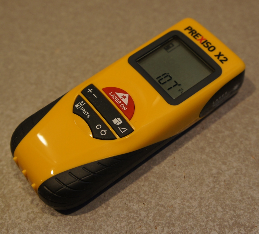
I found the cheapest laser based tape measure on Amazon (Not ultrasonic, watch out!) and ordered it. A few days later the laser tape measure showed up. For being the cheapest thing I could find, I was fairly impressed with the quality of the unit.
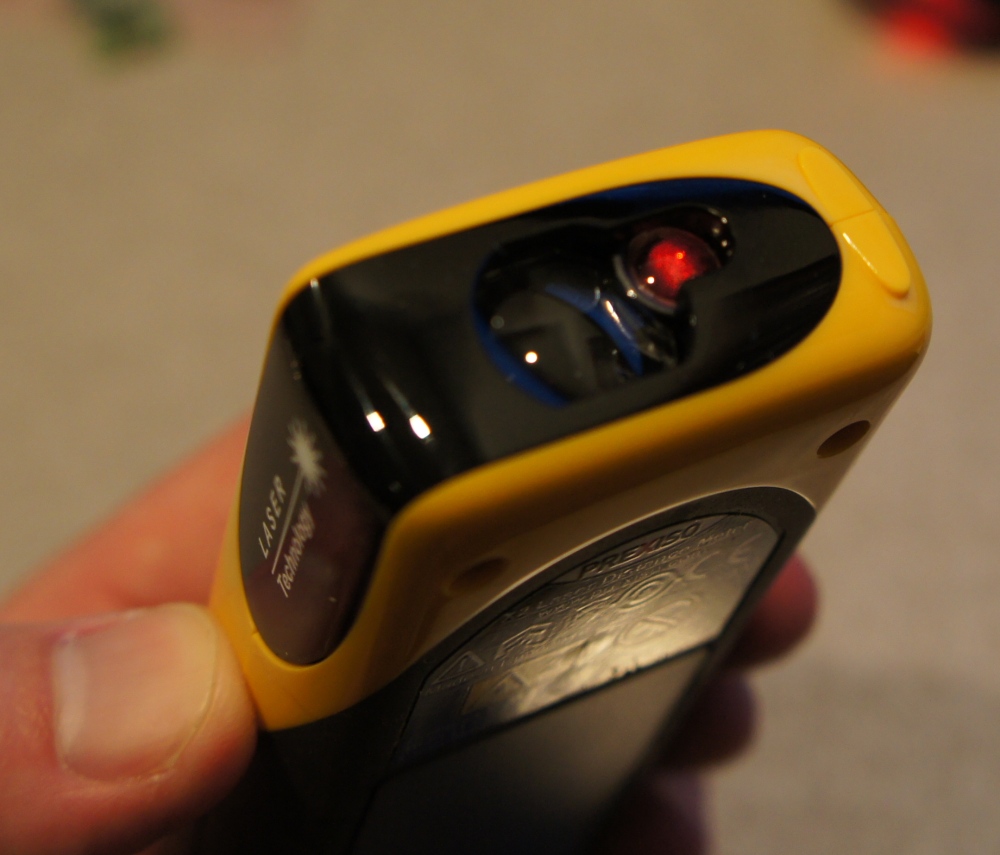
Checkout those optics! You can see the laser diode illuminated on the right. The main lens has two small lenses built into it. I believe this unit uses laser interferometry. It even came with a carrying holster! Oh how you won't see the light of day...
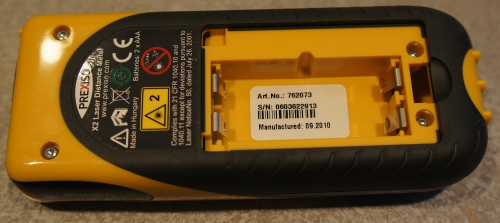
Prexiso is the manufacturer, at least that's what the sticker says - I'm sure someone else actually builds it. I see a few very small torx bits; I think I've got some small tools that will make quick work of those. Everyone should own security bits and other hand tools that will remove small, specialized screws. Right?

Here we go! When hacking, I recommend you start a doc of some sort (I use google docs) and record all the random things you see, in the order you see them. Here's a snippet from the beginning of my log:
10-13-2011
Laser measuring tape from Amazon
Opened up with small torx security bits.
Main IC:
38326A54WV
Leica
777655
BG02868
1029
One side is all LCD connections
20 pins a side, 80 pins total
20MHz
LC14A
TI
CDRH
Small, Crystal is near it but may be unrelated
5 pins per side, 2 sides, 14 pins total.
Near two large pads - EL back light maybe?
A freq test would tell.
http://www.ti.com/lit/ds/symlink/sn74lvc14a.pdf
Looks to be a HEX Schmitt-trigger
Y = A* inverter. Can be used to interface 3.3V to 5V devices.
....
This continues across a couple days worth of rambling. These are not specific or well composed thoughts, instead they are just your initial impressions. I cannot stress how important it is that you record these initial investigations. Later, when you really get stuck it can be very helpful to re-visit these first impressions.
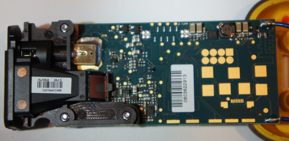
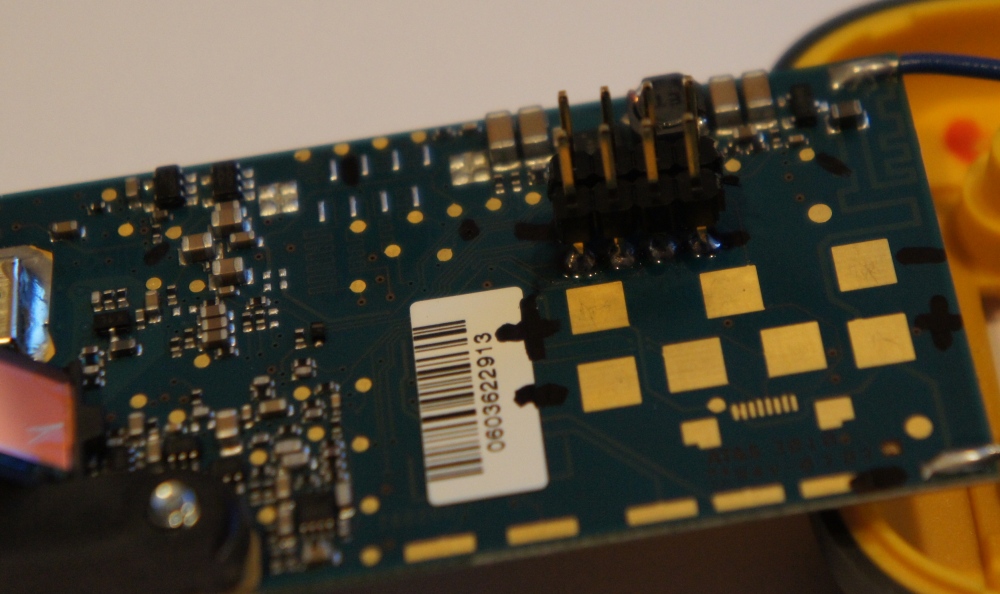
Above is a picture of the back of the main board. Visual inspection of the board shows high quality layout and impedance matching. This is a serious PCB with some serious optics. This hack is not going to be as simple as finding an analog voltage and extrapolating a distance. I'm just hoping that there is some sort of data being passed around the board that will allow me to 'sniff' the data before it goes to the display.

This is an up close photo of the main IC. Initial searching for the IC by Leica produced nothing but hits on microscopes. Not what I'm looking for. Finding a datasheet for such a custom IC is usually pretty difficult so I gave up after about 30 minutes of searching and began probing around the board to identify ground, then VCC.
Continuity on a multimeter is very powerful. It can tell you what pads are connected to each other. Initially, I searched for what was physically connect to the positive and negative terminals of the two AAA batteries that power the device. Using a sharpie marker I marked the pads that had been identified. Then I powered up the unit and identified where power was being stepped up to 4.2V. This removed a few more pads from the pool of unknowns.
With a handful of ground and VCC (both raw 3V and 4.2V) pads removed from the unknown list, I decided to start soldering connection points to the test pads on the PCB. I've said this for the past few tutorials: the Logic Analyzer by Saleae saved my life. It has. If you don't have one, get one. You'll thank me later.
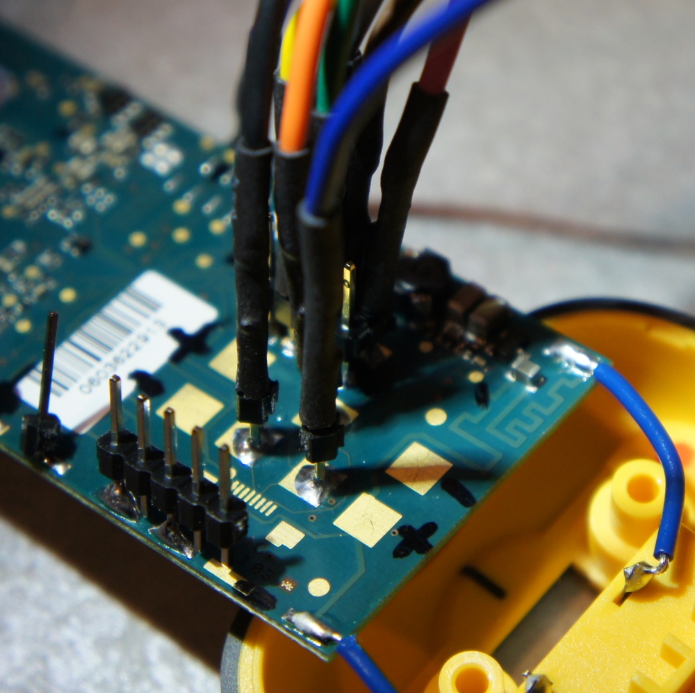
Using the logic analyzer, I first hooked up to the pads that seemed logical. This was a bank of 8 pins (see above, it's 7 round pads with one square pad). If I had to program a board using JTAG, it would probably be here. Note: While probing and hacking, it's important to retain a unit in functioning form. I disconnected the screen, but I kept the button pad around so I could Fire the Laser!

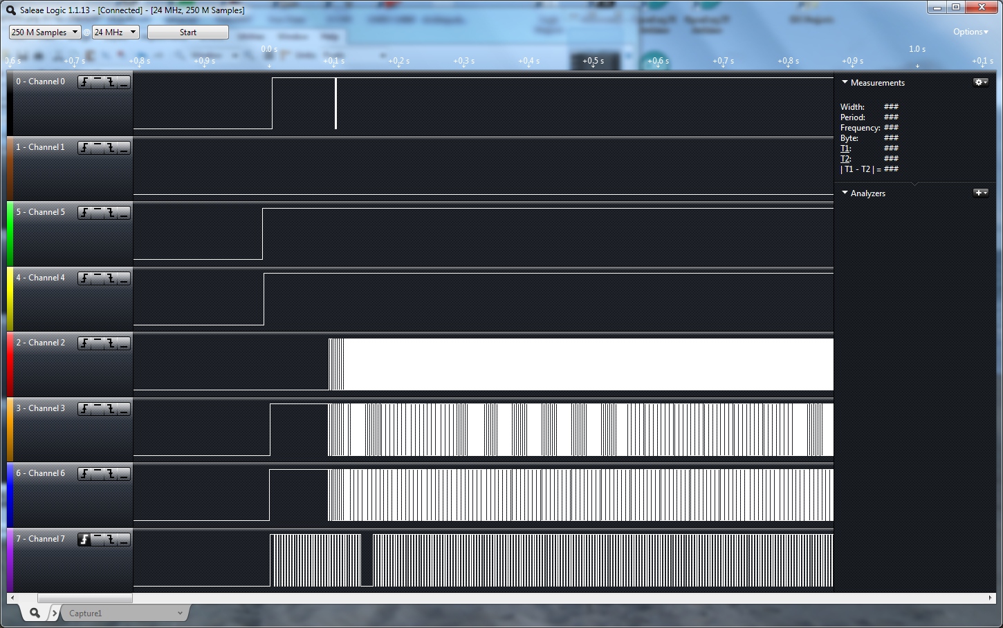
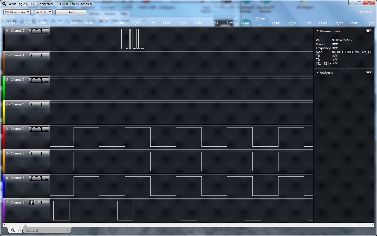
Powering up the unit I pressed the button to measure a few feet to my hand or the wall past my workbench and capture the data forms using the logic analyzer. We can see in the capture above that there are a few lines that do very little (channels 0, 1, 4, 5) and four lines that are very active (channels 2, 3, 6, 7). Let's ignore the channels that don't move for now.
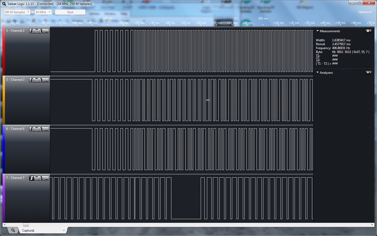
Obviously there's a change in the wave forms at various points. I tried to identify a pattern or change when moving my hand. Unfortunately I'm not intelligent enough to recognize what's going on so I started to probe other pads on the board.
I probed about a dozen pins when I saw a blip. This was unique, it did not repeat. Time to look a little closer.
My heart sped up. Wait - is that serial?

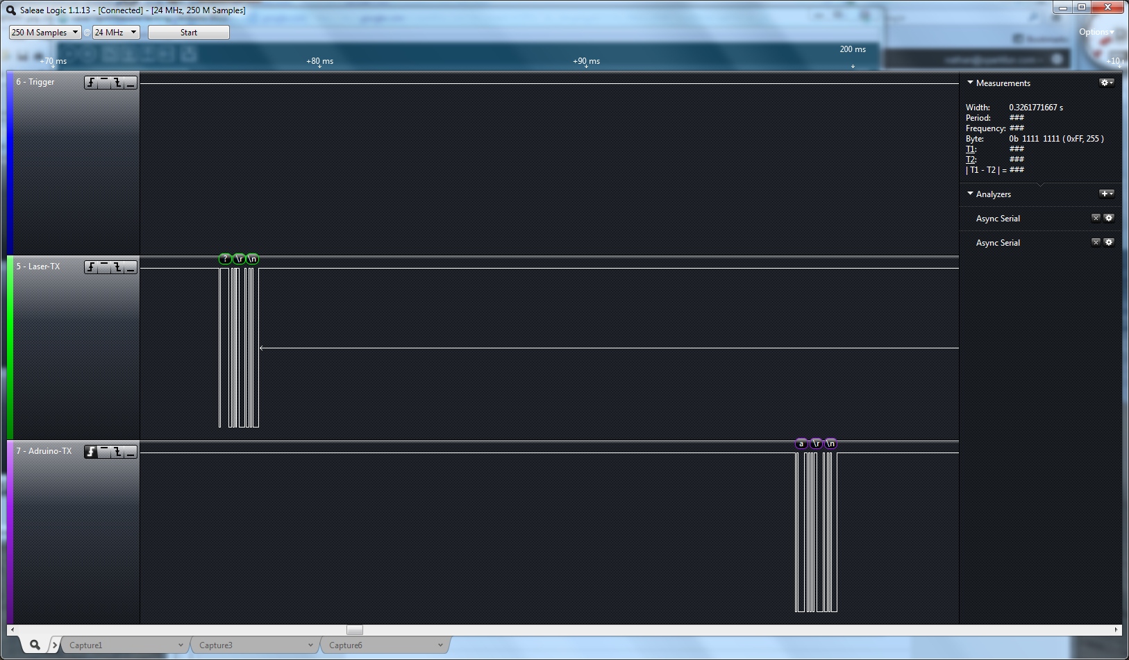
Turning on the serial analyzer within the Saleae logic software, I turned on the auto-baud detect and when the wave form displayed '? \n \r' (? CR LF at 19543bps) I knew that I had found something major.
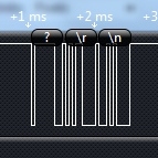
Discovering a random serial character is nothing that interesting. Discovering a single character (especially '?') followed by a carriage return and a line feed is something deliberate and very much the TX pin of the board. The board is transmitting serial! This is great! We've found it!
Once the transmit was found at 19543bps (this is within the margin of error of a very common 19200bps baud rate) I started to look for the RX pin. If I could transmit something sensible into the board then maybe I could gain control of the system. But does '?' indicate a bootloader? When I build anything on a microcontroller I will put a serial bootloader on it. A question mark '?' is a common character I might broadcast during power up to tell the world I could be bootloaded. But this is all guess work. Perhaps the mark means something else? Let the google research begin.
Here's more stream of conscience notes:
10-17-2011
...
More from “Leica Survey Office”
http://www.engineeringsurveyor.com/software/leica/tps400_user_manual_en.pdf
Maybe called theodolites?
http://www.leica-geosystems.com/corporate/en/lgs_405.htm
Laser distance meter software:
http://www.leica-geosystems.com/en/Laser-Distancemeter-Software_5052.htm
Leica DISTO™ instruments - Hmm
Hah! That looks like ours:
http://ptd.leica-geosystems.com/downloads123/cp/disto/lite5/manuals/lite_en.pdf
More manuals:
http://ptd.leica-geosystems.com/downloads123/cp/disto/pro/manuals/interfaceManual111_en.pdf
Downloaded and looking at serial protocol for DISTO software. Talks at 9600bps, Transmits “a” then \r \n.
After a few days of poking around on the interwebs it became obvious that Leica was big into laser surveying equipment. And that equipment often had a serial interface that was 9600bps to log what location and what variables where seen by the equipment. This was a very hot possible lead. What I needed was the ability to precisely transmit a stream or characters (such as 'a' \r \n) at the module. Breakout the trusty Arduino:
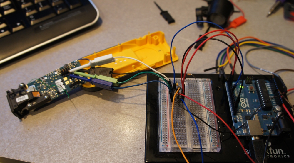
Here we have the laser model connected to a breadboard. The Arduino TX/RX and a GPIO is connected to the breadboard. The logic analyzer is just outside the picture frame and is there to show and verify what serial traffic is going back and forth. We knew what pin was TX, but what pin could be the RX pin?

Here are the pins as I identified them. To try to figure out what pin might be the RX pin, wanted to find where the TX pin was connected to the main IC. UART pins are customarily next to each other on a given microcontroller so it can be very helpful to know what pin the TX pin is on the main IC.
With the unit disconnected from power, I tried probing from the TX pad back to the main IC. For some reason I could not find continuity so I started poking around the main board. I found continuity to a resistor. On the far side of the resistor, I found it was connected to the main IC (pin 10). Measuring the resistor, it was 1k Ohm. Hmm. It's not uncommon to have inline resistors on the TX and RX pins to provide basic electrical protection, so I was encouraged. There is a very large pad next to this TX pad that seemed like it may be the RX pad.
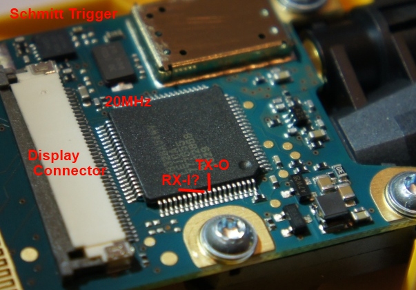
Testing it I found that it runs through another 1K resistor and terminates at pin 11, right next to the TX pin. I assume that this is sufficient evidence that this unknown pad is the RX pin into the microcontroller. With this knowledge I then decided to barrage this pin with data.
It's also important to point out a couple other things. The pad labeled trigger: I found when I pull this pad low the unit activates the laser and initiates a measurement. So I control this pad from the Arduino before waiting to hear the ?\r\n from the unit and before sending any test strings. It's also worth pointing out that there is a footprint for a 8-pin SMD connector just below the large 7 square pads. It is painfully obvious to me that this is some sort of a serial connection.
So let's start hammering the laser module with serial strings!
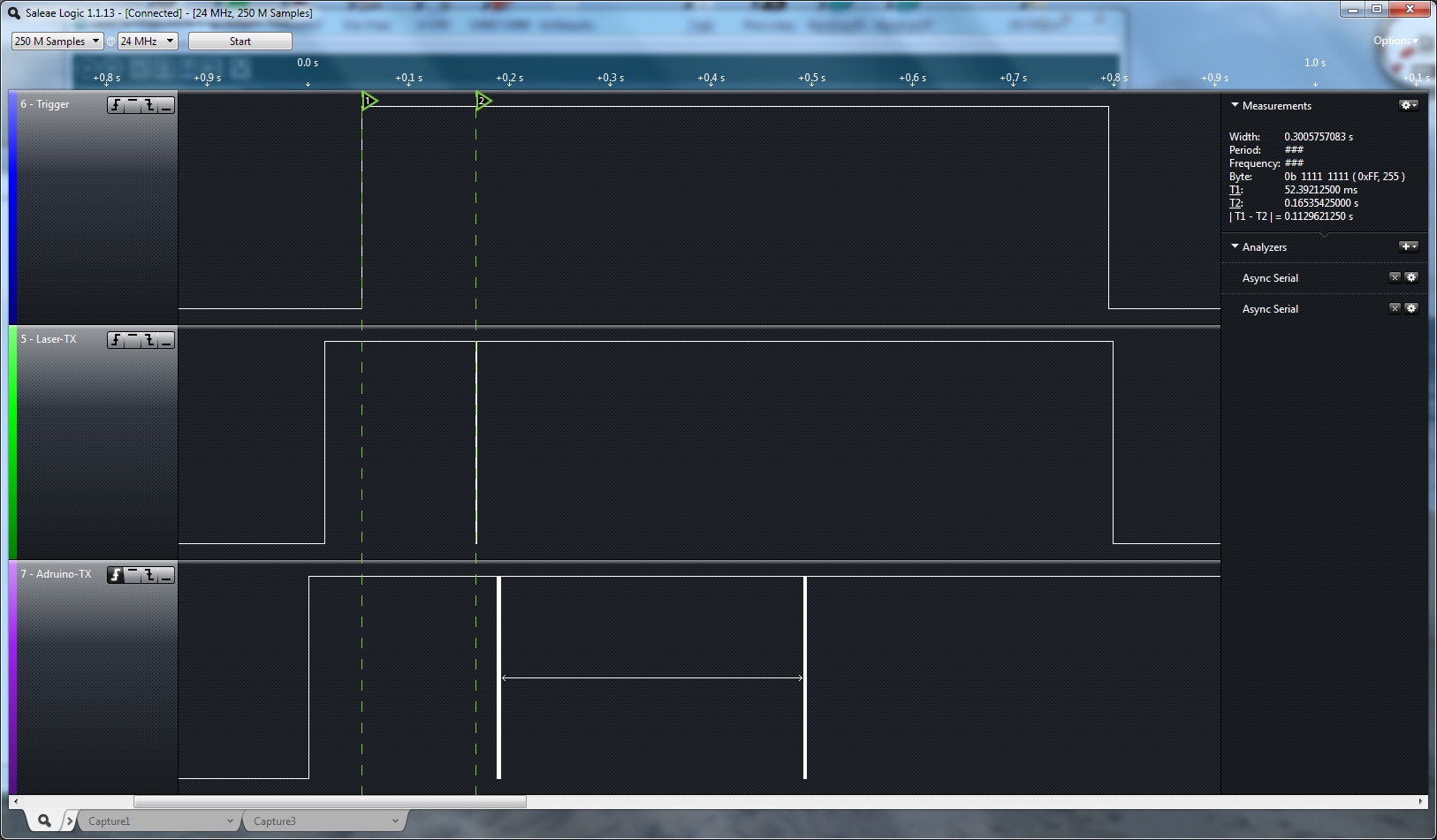
Here we trigger the device, and 112ms later the module transmits the ?\r\n. Shortly after that the Arduino transmits a\r\n to the laser. We see no answer for 300ms so we transmit another a\r\n string. Again, no answer.
Nada. I tried many other strings as well (c\r\n, ?\r\n, SET/32/0\r\n) with no response.

What if we need to transmit some serial before we hear the ?\r\n from the unit? Above we transmit characters before and after the ?\r\n but no other activity is seen.
From reading various serial protocol datasheets from Leica I tried:
- a + CR + LF
- ? CR LF
- SET/32/0 CR LF
- G CR
I tried these and many more, even at different baud rates. I tried transmitting before the unit sends the ?, after it, after the measure button was pressed, pretty much everything I could think of and I have not seen any response from the unit except the the '?' after the initial power on. I also downloaded Leica software that is supposed to connect over Bluetooth (serial port profile SPP) and inspected the characters. Not surprising the software transmits a "a\r\n" string to try to get a response from the device. I tried this string again with no luck.
In the end I have been unable to get the laser tape measure to output anything sensible over serial. I realize that I could connect wires to the display connector (20 pins) and decode the segments that the main IC is lighting up on the main display. This would probably allow me to read the distance, but would be a heck of a lot of work. It would be so much nicer to have serial control of the device.
For English support, Prexiso's website redirects to Calculated Industries - a website that is not at all encouraging. They look like just a reseller/distributor to me. I knew it was a long shot but I decided to ping their support line.
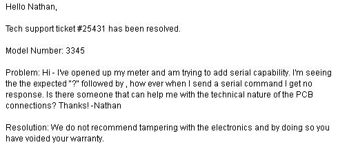
This is a phenomenally awesome 'resolution' if I have ever heard one. It's emails like this that make me want to slap my forehead. They just don't understand what we (the community of engineers, hackers, artists, students, and innovators) are trying to accomplish. Warranties are not a concern to me, instead I'd like to simply be directed towards someone that might know more. Ah well, I knew it was a long shot anyway.
I know there are other laser tape measure meters out there. But regardless of the model, I believe there are very good applications for short range, high accuracy distance sensing. If only the manufacturers added a basic serial interface (they added half?!!), then they might just see a very big explosion in sales because people like us (and we are growing) could then re-purpose their product for other projects. A pipe dream I know, but let's hope for the day.
We're trying to source a good, low-cost solution for laser range finding. If you have any luck hacking similar laser tape measures please let us know!
I saw this on Amazon, this seems like it would be easier to hack... "Prexiso AG iC4 Laser Distance Measure Connector for iPhone 4 or iPhone 4S"
Maybe someone can help me with that one? I have one, already taken appart and made pics of everyting
Another thought. You're thinking that 8-pin connector would have a cable attached to it for debug or communication. A lot of our debug cables will ground a pin when attached, to signal the micro that the cable is connected. The firmware then responds to commands from the cable. Any of those extra connector pins head back to the micro and has a pullup resistor on it?
I'm really surprised you didn't hang the logic analyser off of the RX pin and capture the data coming into the chip from the laser that way while the unit was used as normal. Or am I missing something?
The sensor itself probably doesn't use serial. It is either a phase shift sensor ( in which case it may be an analog output ) or a time of flight sensor ( where it would just be an on/off signal )
So I've been searching for days and finally came across this laser rangefinder module. This is exactly what I have (personally) been looking for. Maybe it will work for some others out there. Either way, check it out:
http://www.egismos.com/index.php?route=product/search&search=Laser%20Rangefinder
In case the link is broken or anything, look up: Laser Rangefinder RS232 There are 3 versions: 30m, 60m and 100m.
I purchased the 100m rangefinder for a project and am having a hell of a time communicating with it. Were you able to get it to work with your arduino?
I got across this project and red it. I am new in electronics but I can not figure out why you did not decided to hijack the photo ic output before the microcontroller chip reads it. I will guess that it is an analog signal that is feed. Well you guy know how a photo ic signal work. Can you please let me know why you did not go that rut? Thanks for the time you put to this project and to my post. Mingo
An add-on interface board for a similar rangefinder (Fluke 414D) is available from Porcupine Labs. http://www.porcupinelabs.com/lr4/
Do you know if similar devices with analog output exist ? I'd be interested to transform one into an optical microphone...
http://www.egismos.com/image/data/support/Laser%20Module/LRM%20RS232%20EV-Kit_re1.pdf ~ON<cr><lf> ~READ<cr><lf>
I have also begun a hack attempt on a Nikon laser 440 It is a pulsed time of flight rangefinder that uses an iterative search method with a gated avalanche photo diode with ~500m range capability. Currently I have it talking to my computer over the serial port but can’t get any data off of it. I have logic analyzer captures, pin assignments, and connection information on the point to point wiring. Most importantly, this rangefinder uses an Altera FLEX6000 PLD which can be reprogrammed over a standard JTAG adapter with their free quartus web edition software. If there was ever a rangefinder that I believed was hackable, this is it.
I have begun a hack attempt on a long range rangefinder, the Bushnell pinseeker 1500 It is a pulsed time of flight rangefinder with 1500m range capability. Currently I have it talking to my computer over the serial port but can't get any data off of it.
I know this is possible the least elegant way possible to solve this problem, but, connecting a micro-controller to the pins of the display would get you the number's being shown on the screen, provided the right pins were tapped into of course, and then setting some array's and matching them to the values would get you a distance. Assigning each segment in the display a values using something like this would help in creating arrays or matching values. ----1----- 2| |3 |----4----| 5| |6 ----7---- The wiring would be done in such a way as to make reading the the display as easy as possible, so that pin 1 would be in a segment 1 type place, pin 2 would be in a segment 2 type place, after pin 7 it would loop around so pin 8 would be in a segment 1 type place and so on. int store[0,0,0,0,0,0,0]; int values[0,0,0,0,0];//a place for every digit on the display. From what I could see there were 5 that mattered int zero_type_one[] = [0,0,0,0,0,0,0]; int zero_type_two[] = [1,1,1,0,1,1,1]; int one[] = [0,1,0,0,1,0,0];//or [0,0,1,0,0,1,0]; if that's how it works int two[] = [1,0,1,1,1,0,1]; int three[] = [1,0,1,1,0,1,1]; //and so on to 9 int final; for (int i = 0; i
I do installations of phased array real-time location systems for passive RFID tags / And some firmware + hardware dev. Accurate setup of the antennas is critical So, I've used the Prexiso constantly, as well as the more fancy Hilti PD 40 which give crazy accuracy. It's really cool to see it opened up, all of us at work have wanted to see the insides but didn't want to break the thing.
We have pretty good contacts at Hilti, and an email of a sales engineer at Prexiso. If I can dig it up will send your way.
I having an Ryobi RP4011 which having exactly same pcb. I was playing with, trying to get in a special menu for calibrating. I found this, I am not sure if it helping on the project: by pressing down "-" and "+" button and then ON button for 10 sec while keep holding on "-" and "+" for another 10 sec and release both button, I entered in some special menus. First screen on my is "0492" for first line and "9194" for second line. By pressing OFF it exit. by pressing any other (ex. "-" or"+" ) it scroll between menus and with ON I can enter to do some changes. At menu named "Addco" it looks we can recalibrate the laser meter.
Unrelated Note: Have you seen this? Pretty nice, good price. If it works and is accurate, I like it. Could interface it with just about anything. SENIC
As an update for everybody, I've found a handheld laser distance meter that provides native serial output (the Uni-T UT390B). I wrote a small article about it at http://blog.qartis.com/arduino-laser-distance-meter/
Can I order a breakout board from you to interface with this? Have you tried getting this distance reading into an arduino?
Hi! I was interested in a project like this one and I wanted to know if it had been solved all the problems that occured before. Do you know an Arduino-Laser Sensor similar to this one https://www.sparkfun.com/products/8502 but laser?
Thank you so much.
The only low cost (less than $1000) sensor I know of is Parallax's Laser Range Finder. There are many more faster and more accurate options if you have more money to spend.
While this might be a bit late, I've been working on getting this laser: http://www.boschtools.com/Products/Tools/Pages/boschproductdetail.aspx?pid=DLR130K#specs interfaced with one of my robots. Having similar difficulties finding and making sense of any serial transmissions on the board, we opted to read the data from the LCD breakout. Currently we've found a special clock line on the LCD (--__--, running at 650Hz) that appears to be used to sync the signals that correspond to the digits on the screen for reading data along with the specialized codes for each decimal digit on the screen. Definitely not the most elegant solution, but after we whip something together with a microcontroller it should be pretty easy to interface with and use for collecting data.
I realize this post is almost a year old but was wondering if the offer was still on the table? I work with laser rangefinders everyday and was thinking you may have more luck with a bluetooth model... I love the idea of this project!
can you help me?
We don't know the make or model of the sensor itself, or we'd likely be offering it for sale. Everything we do know is in the tutorial above. Good luck!
what model of laser transceiver used in this device? I have a project at university, where I have to build a measuring device, and need to know what the best sensor to use. If you can help me, i would be grateful grateful.
I really like the sound of this and might buy myself one after Chinese new year and give it a go.
Have you tried decoding the LCD screen instead? Just look at the text and then strip out the data. It's a workaround, but should work just fine. It's either I2C or SPI protocol based communication to the LCD screen.
I like this idea a lot. Sounds like it should work.
Yeah, I don't understand why hardware manufacturers don't look at us as unpaid sales staff, who are happy to tell people to buy hundreds of these products to incorporate them into other things.
I think they're afraid that we'll attempt warranty returns of our hacked devices, or that we'll overwhelm their support staff with calls.
RS232 on instruments is always a simple interface. No hardware or software handshaking. It is a slow, intermittent communication.
The default should be 9600. I would be surprised if it defaults to 19200.
The Leica chip should be consistent with the Leica Disto protocol. No sense in making multiple formats.
If you do have the correct RX pin sending garbage should get an error code in response. It may be case sensitive. I doubt if they would take the effort to fuse it.
"A" or "EXT" should set it to online mode. The lower case "a" powers it on. Until you get it into online mode the "?" is the only response you will get at power on.
Looks like this would give you the data you want, but not via the serial port, looks like it decodes the screen data.
Nate, you did a good job on hacking, it's almost done... Monitoring the old Leica software, I saw it pulls down the RTS line before sending the already known "power_on/reset" command ('a' \r \n). Moreover, looking at other Leica device's documents with serial interface, I would guess the first two pins on the 8-pin SMD connector footprint could be RTS/CTS.
Another very good idea. I'll be sure to wiggle flow control and see if I can get a response.
Here is direct link what I found: http://lukse.lt/uzrasai/wp-content/uploads/2009/12/interfaceManual111_en.pdf
I too found these software manuals. It seems at Leica "?" is a very common 'ready for next command' response. This is why it is sort of frustrating :)
I did not tested if it is similar, but I have hacked other Leica distance meter. Check this link: http://lukse.lt/uzrasai/2009-12-leica-disto-d3/
The flow control was a good idea, however the block diagram for the serial port on the chip doesn't suggest that they have hardware flow control...maybe software XON?.....maybe... also there is another serial port on pins 21 and 22, anything registering on those pins? Also, the interrupt pin is optional on the chip so its not necessarily required for communication, depends on how the software was written. Good Luck
Well, after reading through what you've provided (in terms of diagnostics and troubleshooting/tracing). I would have to guess that you've actually found the serial Rx pin on the chip (particularly if it traces back to one of the pads near the Tx test point pad. The likely problem, however, is that when the chip was built, it was probably done so with a fusing mechanism, so that after programming/testing/calibration is completed, the fuse is then 'blown' to lock that programming (there would be no need to blow the Tx pin, just the Rx). And voila you have a locked chip that prevents anyone later from communicating with the chip.
This may even be the same chip used in their higher end devices (which have serial connectivity available), and the 'fusing' mechanism would just be for use in the lower end units.
Please understand that this is all supposition and conjecture, though certainly within the realm of probability.
There's a footprint for some external connection - I'd have a look at that.
Nate:
@tamagee is on to a good idea; check out the data sheet pointed at.
Looking at your photo, you do seem to be counting the wrong way around the chip. The big round depression is almost certainly the pin 1 marker.
Secondly, I have one of these here sold as the Fluke 411D but the inside matches your photos completely. This may give you more stuff to google for... good luck!
I'm not going to chase the serial. Look for connections coming to/from that largeish metal shield by the Renesas H8 CPU. That should contain the high frequency oscillators or sensitive phase measurement circuits. 100ft range (30m) signifies an oscillation frequency of 40Mhz IIRC (1/4 wavelength at 300x10^6 m/s over 30m). Accuracy is approximately 1/10000, and I suspect they're using either a capacitor or a downmixed phase comparator to produce a PWM signal, maybe through those hex inverters. Check pins 13, 15, and 17 per the datasheet.
Nate, Two comments. 1) In the past I have found some luck searching the Patent & Trademark Office website for any possible patents. A lot of times these are well documented even to the point of protocols & commands. 2) Have you looked at this: http://www.parallax.com/StoreSearchResults/tabid/768/txtSearch/laser/List/0/SortField/4/ProductID/774/Default.aspx. I know it wouldn't give you the "I figured it out myself" feeling but it looks promising.
Good idea about patents. But I'm afraid it won't tell me much about the specifics of the serial interface.
I've enjoyed watching Joe Grand's development of the laser range finder over the past year. He's put a ton of work into it! But for my project, I feel that an off the shelf solution might be cheaper/easier.
Leica are fairly unimaginative in their command strings usually a character followed by a carriage return and possibly a line feed. I checked some code for the Leica Disto variants and they all use the same fire command - g \r or in binary { 0x67, 0x13 }. If you haven't already try the lower case 'g' with a CR or a CR LF.
It surprises me that nothing shows up on the serial line after pressing the measure button; all laser rangefinders I have worked with in the past return a result via the serial port regardless of how the measurement was triggered.
Some research identifies the processor 38326A54WV as perhaps being made by Renesas - HD64338326XXXWV.
8mhz 8bit.
may have been replaced by 38327 - http://documentation.renesas.com/eng/products/mpumcu/rej09b0144_h83827r.pdf
Pin 10 is listed as timer output, but given the orientation of the chip (pin 1 at beveled corner 1-10 along bottom) I think your pin 10 is actually 71 and 70 is RXD. Pin 69 is SCK. You may need to clock data in. Pin 72 is an IRQ, perhaps chip requires an interrupt to read?
There is another io port on the other side, pins 21-23.
That looks like a great resource!
The RX & TX that are pinned out are from SCI3-2 .... the same one used to program the chip over the serial port. So they may be there more for initial programming instead of actual use. Unfortunately, this is a write-only port ... if you send some zero characters to start the communications, the first thing it does is erase the memory.
To enable this serial programming mode, you need to play with P32 (pin 20) ... I wonder if that's put out to the same pads as the RX/TX?
There looks like a loophole in looking at the code, though -- if you desolder the chip, you can program it in EPROM emulation mode - and, read it, too, but I'm not totally sure. If that's the case, we can reverse the code - it's not that much code.
IF ANYONE HAS A DEAD ONE OF THESE, I'LL HAPPILY TRY TO DUMP THE ROM! Mine's in perfect condition & not ready to break it yet...
Being able to use on of these sensors would be great (so keep it up). But what we really need is to get a hold of Neato Robotics "Revo LDS" sensor (http://www.hizook.com/blog/2009/12/20/ultra-low-cost-laser-rangefinders-actualized-neato-robotics). Just if Sparkfun could contact them and resell their sensor. I talked to Neato at CES this year and it seemed like sharing their sensor was not on their minds at that moment (with the whole getting your company off the ground thing). But maybe Sparkfun could convince them...
It would be nice. The Revo will be capable of significantly higher repetition than this is designed for due to the CCD triangulation they are doing. Achieving the accuracy this tape measure does means they're probably averaging multiple events to produce an average to remove odd glitches in the measurement.
I am going to try to do this. I have a old Radioshack laser tape measure that I will first try it with.
reminds me of when i had to configure bluetooth.might be expecting AT commands? try typing 'AT' or 'at' but i dont think capitalization matters.
connect BT serial to RX>RX, TX>TX "type AT and you should see 'OK' returned"
PS - i remember something ridiculous about "set RTS on close" checkbox in device manager>ports
also if you see ascii i think your baud is fine. no idea though im a beginner.
AT commands - it's worth a try! I'll see if it kicks anything back.
I would laugh my head of if it responded to +++
I wonder if it is using some kind of amplitude modulation on the laser? Apparently modulating at a handful of frequencies and noting the phase shift can yield distance after some linear algebra, so I wonder if a) one could confirm whether there is modulation than varies by measuring the output of the laser with a detector, and b) whether the phase shift is represented in one of the signals you have probed. Very interesting.
From my reading of US patent 5949531 the laser is modulated with a 2ns pulse which changes the arrangement of the sparkles which is in turn compared with the reference transmitted beam to get the time delay and thus the distance.
Clever.
Larry
Hey Nate, great attempt, actually, are you sure the '?' character is really a question mark and not an undisplayable ASCII char ? (I can't figure it out from the waveform). And is it constant no matter what distance you're measuring ?
Good question! Yes I'm sure it's the ASCII '?' (dec 63, 0x3F). Yes I'm sure it does not change. I believe the ?rn shows up before the measurement is finished.
Very interesting! I love a good puzzle.
I wonder if some sort of flow control is used.
It is interesting that you see the ?/r/n response when you trigger the laser. According the the DISTO protocol that is possibly a response to a command. If it is just a general ready for new command you would think it would only show up once on startup. Because it shows up ever time you press the trigger it makes me wonder if the trigger sends a command to the processor via another route.
Just some thoughts. Good luck
That's exactly how I approached it - a heck of a frustrating but fun puzzle.
Good point about flow control. That's the sort of ahah I need. I'll see what I figure out.
To clarify, ?rn only shows up only after initial power up. If you press the regular measure button, ?rn shows up once after power on, then never again. The trigger pad seems to be connected to the DC to DC step up, I believe causing the unit to fully power reset (that's why we see the ?rn after each trigger).
Sounds almost like a test suite/bootloader command line even.
That was my original gut feeling was that ?rn was a bootloader announcing to the world it's alive. But after reading the Leica documentation, ?rn is used far more often as a response to a command than it is having anything to do with a bootloader. But then again, I'm just guessing.
Nate, we'll try it.
UPDATE: Did some more digging, and that's apparently the protocol for an aftermarket Bluetooth add-on, not for the newer Bluetooth-enabled factory models. So it seems that's a "nevermind, nothing to see here". D'oh. May just have to install DistoTransfer on a PC and do some data sniffing to reverse engineer it, unless I can track down the API docs. They seem to keep them pretty locked down, though, so I'm not holding my breath.
I can't help with confirming that the serial protocol is the same as their Bluetooth models, but since they use SPP (well, until the newest ones that are iPhone-friendly), it seems a reasonable assumption. That being the case, after a few days of digging and trying to find the magical combination of keywords to coax it out of Google, I found the documentation for the Bluetooth serial spec:
http://paperless.bheeb.ch/download/DistoXAdvancedInformation.pdf
I'm hoping to sit down and try to get an OS X client for it going, since I haven't been able to find any commercial solutions, and Leica just shrugs and says, "You need to find a third-party solution that fits your needs for OS X support." More to follow...
I concur with qartis. I am able to easily pull the serial feed from the Uni-T UT390B. I am not, however, able to issue commands to the device. I need to push the "on" button to take a reading. Not ideal because i want it to turn on, take a reading, turn off, all as fast as possible..
As such, I will buy one of the UT390B devices for one member here who is willing to put serious time and energy into seeing what commands can be sent to the device. It is pretty accurate too! (Note, the UT391 is more accurate and also LOOKS like it has accessible serial contacts. Nate, are you still interested? The battle is half-way won. See the output below.
any luck with UT391?
the commands are:
*00002#- takes 3 measurments in a raw freezes
*00004#- take a measurment
*00005# - memory dump
*00084553#- rapid measuring
taken from: http://blog.qartis.com/laser-distance-meter-update-serial-commands-timing-measurements/
Maybe it's compressed data. But that is not likely, as the message is just a couple pieces of serial crap... Hmmm...