
PowerCell Quickstart Guide
Overview
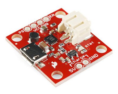
The Powercell board can serve many purposes. The board is a single cell LiPo battery charger, along with an efficient regulator, that can supply 3.3V or 5V power to your project. The Powercell can also be permanently connected to your system, so that you will never need to remove the battery from your project.
This guide will go over how to charge your battery and how to add power to your system, as well as cover some of the configuration options for the Powercell.
Requirements
Here are a list of supplies you will need if you want to use the full features of this board.
- Soldering Iron w/ Solder
- micro-B USB Cable
- Powercell
- single cell LiPo battery
- Arduino or any other system that needs regulated power
- Break Away Male Headers - Right Angle
- Jumper Wires Premium 6" M/F Pack of 10
What it Does
The Powecell can act alone as a single cell Lipo battery charger, it can act as a boost (5V) or buck (3.3V) regulator for your project, or it can perform both of these functions. No soldering required, if you are only using the board to charge your battery over USB.
Battery Charger:
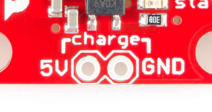
The charger on the Powercell uses the MCP73831 from Microchip and can supply up to 500mA to a single cell LiPo battery. If you charge over the micro-B USB connector, the charge current will be 100mA. You can also externally charge your battery using the pins labeled 'charge' using your own 5V power source, at 500mA.
The red stat LED indicates charge status and is ON when charging and OFF when fully charged.
There is also an under voltage lock out (UVLO) set at 2.6V with a couple of resistors, along with a jumper on the back of the board to disable the UVLO. The UVLO prevents your battery voltage from dropping too low and damaging the battery. Only advanced users should disable the UVLO.
Regulator:
The Powercell uses a TPS61200 switching regulator, from Texas Instruments, with a 3.3V or 5V output. The specifications for how much current you can use from this board are as follows:
- 5V @ 600mA max
- 3.3V @ 200mA max
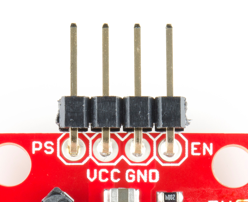
The enable (EN) and power save (PS) pins are broken out and pulled high (enabled), so that you can shut off the regulator to save battery power. If you are permanently connecting your Powercell into your system, you will need to control the EN pin, so that when you are not using the system (all power OFF), the regulator can be shut down as well. You can shut down the regulator by pulling the EN pin low (GND). More information on pin functions in the TPS61200 datasheet (Resources section below).
Note: Pulling EN and PS low greatly reduce current drain on an attached battery but do not completely eliminate it. If you are going to be storing the Powercell for more than a day or two, disconnect the battery to prevent completely draining it and causing damage to the battery.
How to Use it
There are two basic circuits on this board, and each can be used independently or together. I will go over both options.
Battery Charger
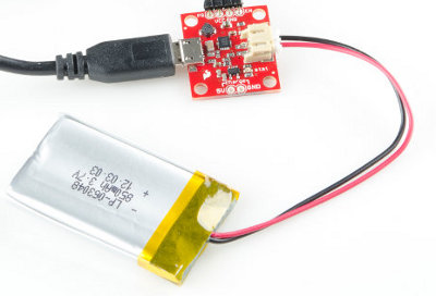
If all you want to do is charge a battery, simply connect your single cell LiPo battery to the JST connector and a micro-USB cable from the Powercell to your computer, no soldering required. You should get about 500mA charge current and the red charge LED labeled 'stat' will light when charging and go off when finished.
You can also use your own 5V supply and charge over the charge pins labeled '5V' and 'GND.
NOTE: When you are finished charging your battery, it is recommended that you remove the battery from the Powercell, since the charge will slowly drain without proper management. Or keep reading and learn how to control the charging and regulator output.
Using the Battery Charger and Regulator Together
If you want to use the regulator and charger as one system, there are a few extra things you will need to do to fully control the board and keep the battery charged. Below, we will outline an example setup. There are many other ways to do this, this is just one:
Step 1
It is highly suggested you solder your connections to the Powercell. Solder headers or wires to the 4-pin header.
Step 2
Select your output voltage.
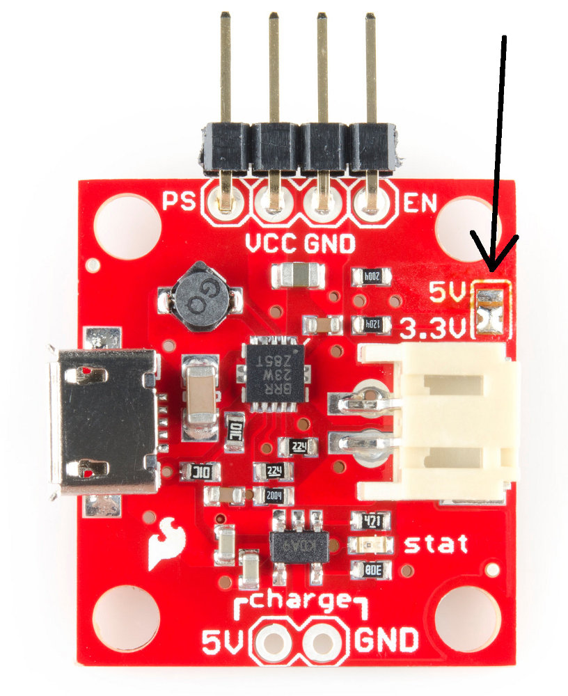
Jumper shown above is selected for 3.3V.
The board comes with 5V enabled (center pad and 5V connected). If you want to use 3.3V, clear the solder blob over the 5V pad and move it to the 3.3V pad (center pad and 3.3V connected). The safest way to do this is with some solder wick, or just turn your soldering iron down to a lower temp and move the solder blob with the iron's tip.
Step 3
When you connect your battery to the Powercell, you can power your system/load/Arduino with 3.3 or 5V. However, there are some control mechanisms that you must not overlook.
There are two main modes you can use (there are other configurations):
Charge Mode:
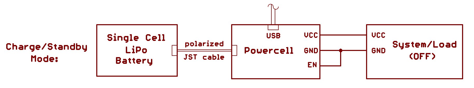
If you want to charge your battery or just let you system standby, with no power draw from the battery, you must pull the EN pin to GND (by default it is pulled high, ON). The EN pin turns the regulator portion of the circuit ON and OFF. Even if you have only your battery connected, you should still connect EN to GND.
Power Mode:

When you need to power your circuit, you can leave EN floating (no connection) or pull it to VCC. If you want to have USB charging as well, that is fine, it won't hurt anything.
Here is an example setup:
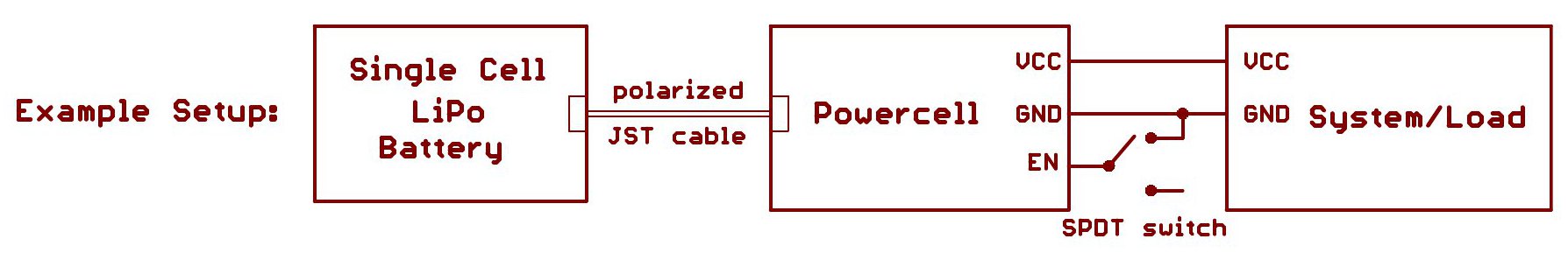
A good way to use the EN pin is to connect a SPDT switch. This way, you can turn everything OFF and ON.
Also, in any mode, you can charge the system, as long as the current draw from your system doesn't exceed the charge current. If your system is drawing more than the charge current, then you battery will just deplete and never charge.
In summary:
EN is high (VCC, default), Powercell is ON
EN is low (GND), Powercell is OFF
Troubleshooting
- If for any reason your battery will not charge and the charge LED is ON and will not go OFF, unplug your battery and plug it back into the Powercell and try to charge again.
- If the above doesn't work, then you might of drained your battery all the way past the cut-off on the battery itself. Please contact techsupport@sparkfun.com
Resources
- Eagle Files
- Schematic
- Datasheet (MCP73831T)
- Datasheet (TPS61200)
If you have any trouble or if something doesn't make sense please drop a comment in the box below.
From the schematic of the breakout board, the EN pin is connected to VBATT through a 10KOhm pullup resistor.
So, when I need to shut down the PowerCell, I draw 100s of uA from the battery through the pullup resistor forcing the EN pin to GND.
How is that power saving?
In comparison, the TPS61200's current drops to 1uA in shutdown mode (EN=GND) from 50uA in quiescence regime (EN=VBATT & IOUT=0A). In other words, the pullup resistor draws many times more current than just letting the PowerCell run with no load.
If you care about power-down current, then it seems you should desolder R2 (the EN pullup) and replace it with your own circuit with a pulldown to ground and an active high. But that's not very beginner-friendly; it forces everyone to worry about the EN pin instead of supplying something which "just works" for most people.
So I agree with the logic of the circuit as provided, although I agree that the tutorial could be more explicit about the fact that "just" driving EN low isn't sufficient to minimize power draw. If they did a revision on the board, I'd suggest replacing the EN pad with a cuttable trace to the pull up resistor to make it clearer that, if you're thinking about driving EN, the first thing you need to do is disable the pull-up.
Could somebody explain when you do and don't want to mess with the PS pin?
Can we get an explanation on the PS pin? When should it be high and when should you pull it low. Provide some example situations please.
I second this question. Is power saved mode enabled by default or does it need to be pulled low or high?
The schematic has it pulled high with a 10K resistor. The TPS61200 data sheet says you pull PS low to make it active.
As for what it does...it looks like it makes a tradeoff between power efficiency and output voltage accuracy. If you pull PS low, you get more ripple on the output, but more power efficiency with smaller (1mA-10mA) loads. The device uses shorter bursts of higher current because it's most efficient between the middle and top end of the operating range.
Hi there, is there any other option which would allow me drawing much higher current? I'm trying to make project with LED strip and my top draw is around 6A. I would like to keep data connection from PC to dev. board while charging battery and operating the LEDs.
-------------------- Tech Support Tips/Troubleshooting/Common Issues --------------------
Current Draw When PowerCell Enabled and Disabled
Using a multimeter, I noticed that the board would pull about ~7.73mA to ~7.32mA of current with a LiPo battery attached and no load. This is normal because the booster circuit is pulling power to boost the voltage to the output pins. There is also, the enable (EN) pin that you can ground in order to turn the circuit off. The TPS61200 IC will still pull about ~0.42mA.
Default Charge Rate and Safely Charging a LiPo Battery
The default charge rate is set to 500mA. If you are interested, here is more information about safely charging LiPo batteries [ https://learn.sparkfun.com/tutorials/lipo-usb-charger-hookup-guide#setting-the-charge-current ]. The LiPoly charger uses the same charge IC and application circuit.
Am I just simple, but rather than deal with pulling EN low, why not just put the switch inline with the LIPO? No trickle current no nothing....
Set to 3.3v via jumper. Output voltage reading as 3.18V. Charging current reading only 50mA and 4.1V. Seems defective to me.
Hi,
A couple of things with this:
The tutorial says that charging over the microUSB port will draw 100mA, and charging via the 5V/GND charger pins will draw 500mA. I've tried both ways using a USB Charger Doctor and it draws 500mA+ through both methods. So it sounds like this can't be used with <500mA batteries using either method. Is there a way to modify the PowerCell to charge at a lower rate?
The 'scale' photo on the product page is too big - this board is definitely not 2x2" :)
would it be possible if I connect 2 single-cell LiPo batteries in parallel , and connect to the PowerCell?
Hi I have been trying to charge the battery using the 5V charge input. The red stat(us) led lights up but there's no output. I've been using these boards with USB and there was never a glitch but charging them using 5V charge input seems to have killed the boards - 2 of them! There's no output on either of the boards used this way. Any advice will help
If the above doesn't work, then you might of drained your battery
I think it should say might have drained.
would it be possible if I connect 2 single-cell LiPo batteries in parallel , and connect to the PowerCell?
I was hoping to get an effective 2X capacity combined battery.
So is en pulled to battery's ground.
The TPS61200 circuit is not working properly. The PowerCell board is brand new, I just unwrapped it. The LIPO is brand new, I just unwrapped it. Both just arrived in the mail from SparkFun. The output voltage is set to 5 volt on the board (the setting it came as). I plugged in the LIPO, its voltage is 3.83 volts. The output voltage (VCC to GND) is 3.17 - 3.19, no where near 5 volts. It's not working, may be defective. This is being tested without any pins soldered to it (bare), using voltmeter probes. The PS an EN are not connected to anything and are at 3.82 V (referenced to ground). It may be defective. I cannot get it to work. Help!
If the prog pin is always pulled down by a 2K resistor, how does this ever limit @100mA (whether or not connected to USB)?
I would like to remove the 10K resistor from VIN to EN and connect it from EN to GND. Following the trace, it looks lite it's the one right next to the big cap by the USB jack. It looks like it is soldered right on top of the via. Could you confirm this? Could you also recomend an iron temperature for the type of solder used to assemble the board?
Could some one post a picture or explain to me how exactly to wire an SPDT switch. What goers where?
Thanks.
When leaving the floating (as in Power Mode), and with a usb power supply connected, does that mean the power supply is charging up both the load and battery? If the battery is already fully charged up, will it stop charging by itself or the battery is actually draining and charging at the same time? I am considering using this as a UPS system for my Arduino, thanks!
As soon as the micro USB is connected, the MCP73831 generates the 4V that feeds the VBAT supply.
So, it charges the battery and feeds the 5V DC/DC converter (TPS61200).
Just wondering... It says above that "[...] it can act as a boost (5V) or buck (3.3V) regulator for your project, or it can perform both of these functions."
But how can it perform both (deliver a 3.3V and 5V output at the same time) if there's only one VCC pin?
I think the "both" refers to acting as a charger, and as a supply. As a power supply it's limited to only one voltage (jumper selectable).
What is the best way to read the remaining battery level? I believe, soldering a wire to JST connector would be the simplest, right?
Hi guys, I need some advice.. The inductor being used on this powercell is 4.7uH, 1.2A Sumida CDRH2D18. May I know if there is an alternative inductor that can be used to replace this?
The powercell board from sparkfun is too large for my project, so I need to replicate the design and integrate it with my PCB design. However, the inductor being used in this device is not sold in my country. So I'm wondering if there is an alternative to this. I tried using a similar 4.7uH, 1.2A power inductor from Wurth Elektronik, but it got burned out after 30 minutes of charging. Any suggestion is much appreciated.
Is that OK to leave the battery attached to the project while charging or is it necessary to remove the battery and place it on a safe surface before charging? Thanks
I have an Arduino Esplora that I'm going to use this with. If I run a 5V line from the Esplora to the 5V charge pin and also to the Vcc pin, will I be ok? I want the power from the Arduino's USB connector which will be exposed to be available to charge the battery and when I disconnect it, I want the battery to take over.
I will have a switch to allow me to turn off the system when it is not connected to USB and know I'll have to disable this board.
Hi!
Two questions -
If there is no system/load connected to the power cell, will the battery still drain or must I install a SPDT switch?
I'm thinking of using it as a solar charger/batterypack.. Can I connect a 8v 310mA solarpanel via the the 5v input?
thx!
I'm using one of Sparkfuns batteries and maybe the under voltage protection is enough to leave it connected to the Powercell (such a pain to remove the JST connector).
Is there a standard way to connect to arduino to use it's usb port to charge the battery so I don't have to expose 2 separate usb connectors? Thanks...
You should be able to use the 5V output from the Arduino as an input to the 5V charge pins on this board. I haven't checked the current requirements or capacity on the Arduino, though.