
Ethernet to Color LED Matrix
Written by Owen Osborn, olde-tyme SFE Hardware Engineer
owenosborn there-at gmail.com
Open-Source methods for embedded TCP/IP networking. This tutorial will show you how to control a full color LED matrix from anywhere in the world using a Java script on the remote computer and an ARM development board connected to a tri-color serial LED matrix listening to a specific UDP port.
Intro
The new Color LED matrix controllers from SparkFun Electronics provide a fun way to control 8 x 8 color (RGB) LED matrices. Connecting directly onto a common cathode RGB 8 x 8 LED array, the controller "back pack" provides a simple serial interface to the LEDs. This eliminates the headaches of switching 192 discrete LEDs on and off.
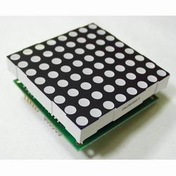
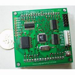
RGB LED matrix controller board. Check the datasheet for more info.
While this is all nice, we still need some way to control the LED controller; something that will send it the image data. This tutorial focuses on controlling one or more LED matrices over TCP/IP using an embedded ethernet board. The LED array becomes a server on the network and may be updated from any computer on the network running a simple JAVA client program. This is a versatile way to control the matrix and it allows for huge expansion. In this tutorial, one LED matrix is connected to the network. But using the same techniques, many LED matrices may be controlled over the network. And if this network is connected to the internet and properly set up, the LED matrices may be controlled from anywhere in the world!
This tutorial is also a good starting point for other projects involving embedded networked devices; the same principles may be applied to any device that needs network connectivity.
The whole project is open source, and does not rely on any proprietary components. The schematics for all the hardware are freely available, as is the source code.
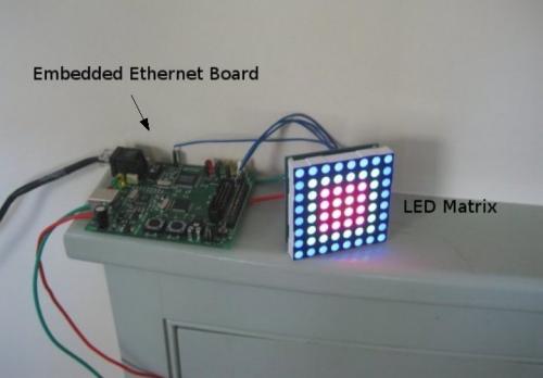
The LED matrix server setup: an ethernet enabled microcontroller board connected to an LED matrix.
Connections, TCP/IP
The most common set of protocols that computers use to communicate on networks is TCP/IP (or the Internet Protocol Suite). The most common protocol in the suite is the Transmission Control Protocol (TCP) which allows two machines to establish a connection and pass data reliably. TCP is the protocol we use to establish a connection between the LED matrix server and the Java client program.
On a network, machines are identified by IP addresses. This is the familiar 4 numbers separated by periods (192.168.1.1 for example). In addition to the IP address, machines have a number of ports which they can establish connections on. The machine is kind of like a large office building, the IP address is analogous to the street address of the building. The individual offices are the ports, providing different services to incoming information. On modern computer systems, many of these ports are standardized. For example a web server application is always on port 80.
In this tutorial the LED matrix server is assigned a known IP address and waits for connections on a specific port (we'll see how to specify these later). This is also called listening on a port. It just hangs out on the network and waits for something to connect. We use a Java program (the client) to connect to the LED matrix server and send it data for the LEDs. The Java client can be run from any machine on the network. Java has lots of functionality for opening and managing TCP connections, which is why we used it, but any programming language capable of opening TCP connections would work. All that the client needs to know is the IP address of the LED matrix server and the port number.
TCP provides a reliable way to send data between machines, but dealing with the data is up to the software on each side of the connection. Once a TCP connection is established, data is literally packets of raw bytes. Further protocols must be written in software to deal with the bytes. For the cause of simplicity, this tutorial has no special protocols on top of TCP. Once the Java program connects to the LED matrix server, it sends packets of bytes that the embedded ethernet board pipes directly to the LED matrix. There is no encoding or anything, the size of the packet is the number of pixels (64 in the case of a single matrix), one byte per pixel. In the end, its as if the JAVA program is connected directly to the LED matrix controller(s); the network connection is completely transparent.
LED Matrix Server
Hardware
The embedded ethernet board is responsible for connecting to the TCP/IP network, and sending data to the LED matrix controller(s). To implement an open source embedded network project we need a board with a microcontroller and an ethernet interface. The microcontroller handles all the TCP/IP tasks (known as the TCP/IP stack), and sends data to the LED matrix controller(s). The ethernet interface is a chip that handles all the low level ethernet signaling (sending and receiving data frames). It is usually connected to address and data lines of the microcontroller.
Many such boards are available, and we choose an Olimex LPC-E2124. This board has a Philips LPC 2124 ARM processor connected to a Cirrus CS8900 ethernet interface. In addition it has a built in ethernet jack and isolation transformer. It also has headers for the IO pins of the microcontroller which are used to connect to the LED matrix controller(s).
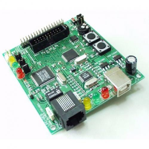
The Olimex LPC-E2124 ethernet board. The USB connects to the LPC UART via an FTDI USB-UART bridge. Using the Philips bootloader, the board can be programmed over USB. Check out the schematic.
Software
The source code for the LPC-E2124 is in the folder LPC-E2124_source of the source code folder.
TCP/IP is not a trivial protocol, and writing a TCP/IP stack for a small microcontroller is not an easy task. Thankfully, there are a number open source TCP/IP stacks designed to run on small embedded processors. We use the uIP (for micro IP) stack written by Adam Dunkle. uIP is a great little piece of software, is very well documented, and may be easily ported to a number of controllers (it has been run successfully on 8 bit micros like the AVR, for example). Anyone trying to work with these tools should really become familiar with the uIP documentation. Check out the documentation for uIP here: html or pdf.
uIP requires a driver for whatever ethernet interface is being used. This is the hardest part in porting uIP to different embedded ethernet boards. Luckily someone has already ported uIP to the Olimex LPC-E2124. Paul Curtis is to thank for this effort, his port of uIP allows TCP/IP functionality on the LPC-E2124 without any driver level coding. The port is available on the Rowley website.
In addition to the TCP/IP stack, uIP provides a bunch of application level functionality: telnet services, an http server with some basic CGI functionality, and even SMTP email. The example above from Paul Curtis is a http web server, allowing any web browser on the network to connect and view some simple web pages. Its worth looking at the web server example to see how an application level protocol like http is coded, although the LED matrix server is actually much simpler than an http server.
uIP provides an event driven API in which an application function is called when a TCP event takes place, such as the reception of new data. So to write a TCP/IP application, all the programmer needs to do is implement a single application function. This function is defined with the macro UIP_APPCALL in the uIP options file uipopt.h (near the bottom). All our TCP/IP application needs to do is pipe the received TCP packet to the LED matrix controller(s), so the function is very simple:
void ledcontrol_appcall(void) {
if(uip_newdata()) { // if new data arrived
uip_send("Packet Received OK ", 19); // sends this back to client
send_led_64(uip_appdata); // send data to LED matrix controller
}
if (uip_rexmit()){ // if a re-transmission is required
uip_send("Packet Received OK ", 19);
}
}
Thats it! Thats the whole application, not very complex, but a good start. In addition to piping the received data packet to the LED matrix controller(s), the function also sends the string "Packet Received OK" back to the client. This function is in the file ledcontrol.c, which also contains the hardware level functions for communicating with an LED matrix controller (such as send_led_64).
You might be wondering about the IP address and port number for the application. This is taken care of during the initialization sequence in the function main(), in file main.c. The IP address, netmask, and address of the default router are set statically as part of the initialization sequence. The IP address must be set so that it doesn't conflict with any other devices on the network that may already have that IP. Remember that uIP does not support DHCP by default, and conflicting IP addresses might cause network problems. Bring up the configuration page for your router (or talk to the network administrator) to see what the DHCP range is set to, and then choose an IP address that is not in that range. For a router IP and netmask, 192.168.1.1 and 255.255.255.0 are common, but double check for your network.
The Port is set in the application initialization function, ledcontrol_init(). The application init function for the LED matrix server just sets uIP to listen on port 3333:
void ledcontrol_init(void) {
uip_listen(HTONS(3333));
}
After initialization, main() enters a loop in which it maintains uIP related tasks like checking for received data. Other general purpose functionality could be put in this loop as well. The yellow status LED on the LPC-E2124 should flash on and off periodically, indicating that the system is running ok.
The source code for this example was compiled using Rowley's Crossstudio for ARM compiler. In the source code folder, there is a project file that you can use if you have Crossstudio (there is a demo version of Crossstudio that will fun for 30 days). The precompiled hex file is in the ARM Flash Debug folder. There is nothing particular to the Crosstudio compiler in the code, so its possible to use the GNU toolchain (or another compiler), although a makefile, linker script, and startup file will still be needed.
Java LED Client
The Java code for this tutorial is in folder Java_Client in the source code folder.
The main purpose of the Java program is to attempt a connection to the IP address and port number of the LED matrix server and, after a connection is established, pass it image data. The example program also provides a graphical front end for controlling a single LED matrix:
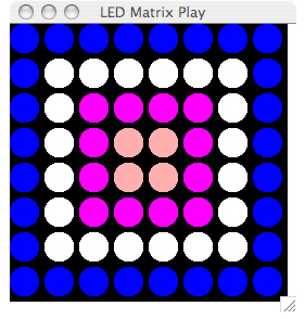
The program is divided into 3 classes: BoardDriver.java, DrawBoard.java, and TCPSend.java. The main() function is in BoardDriver.java. It creates a window and adds some mouse listeners. It also creates a DrawBoard object which is like a virtual representation of the LED matrix. The DrawBoard object responds to mouse events that turn individual LEDs on and off, draws the current LED matrix to the screen, and also establishes a TCP connection and sends data out. To establish a TCP connection it creates an object from the TCPSend class. The constructor for this class attempts to open a TCP connection to the given IP address and port. If a connection is not possible, it shows a warning message, but then runs the graphical part of the program anyway. TCPSend also has a small method writeLED() for sending data out.
The IP address and port number are in the TCPSend class, so it must be recompiled every time these need changing. This is a pain, but could be easily improved so that they can be adjusted at runtime.
To compile the java program, open a terminal if your using Linux or Mac OSX, or a command prompt if using Windows. Move to the directory of the java program and type:
javac BoardDriver.java
Then to run the program type:
java BoardDriver
(note Java must be installed to run the commands javac and java)
You can run the program without an LED matrix server on the network (or even without a network connection) to try out the graphical part. Clicking the mouse on LEDs will turn them on. The color cycles through with each click. Dragging the mouse will set any LED its dragged over to the current color. This behavior can be changed easily in the DrawBoard class.
This java program is provided as an example, and may be changed to suit different needs. For instance, functionality could be added for animation, displaying text, etc.
Expanding the System
Adding More LED Matrix Controllers
The example code with this tutorial is for controlling a single LED matrix controller over the network, but it is very easy to add more LED matrix controllers to the same embedded ethernet board. Each controller needs 3 lines for the serial interface: clock, data in, and chip select. All of the LED matrix controllers may share the clock and data in lines, and all that is needed is an individual chip select line for each matrix controller. There are plenty of extra IO pins on the Easy Web 3 board that may be used for chip select lines to multiple matrix controllers.
Next, the firmware for the Easy Web 3 will have to be updated to accommodate the extra matrix controllers. The same code that sends 64 bytes to the single matrix can be used, all that needs changing is the chip select pin.
The Java program will also have to be updated to send a larger packet (in the method writeLED() in TCPSend), and to display more LEDs in DrawBoard. Keep in mind that there is a maximum TCP packet size, so for a large number of LEDs (more than say 500), multiple packets will have to be used. Then there will have to be some kind of protocol for indicating which packet is for which part of the LED array.
Internet Enabling the LED Matrix Server
Getting the LED matrix server on the internet will depend on how the network is setup, but here are some hints if you are on a small LAN (home or small office).
The easiest way to get the LED matrix server on the internet is to use port forwarding. Most routers can be set up to forward a request for a port from outside the network to a specific IP address behind the router. If the router is connected directly to the internet (via cable, DSL, or some other) the router will have an IP address assigned by the ISP (or you might have a static IP). In either case you can go to some site like www.whatsmyip.org to see what the IP of your router is. If a machine over the internet tries to open a connection to the IP address of your router and the port number of the LED matrix server, the machine will be directed right to the LED matrix server. So the machine thinks its talking right to LED matrix server, as the router forwards the data there:
IP address of router:port 3333 ----> IP address of LED matrix server:port 3333
To use this method, you have to configure your router to do so. This depends on what kind of router you have, but usually it just entails going to the router's configuration page.
Hi JamesHB,
I'm a embedded system consultant in Canada and wonder if I can help with your project. I've helped many local customers with their microcontroller projects and had product manufactured in the US. Send me Email (dngyan@hotmail.com) if you need any help.
As an art project I am looking to make a led message scroller that scrolls a message around a circle that is around 40cm in diameter. This scroller would have 230 x 7 leds, a total of 1610. It would scroll a set message which would go around anticlockwise without beginning or end. Here is a sketch:
http://img210.imageshack.us/img210/2099/diagram2.jpg
I know a bit a microcontrollers but this project is way beyond me...Any help or pointers in the right direction would be greatly appreciated!
Thanks
I have been struggling, trying to get the Java files to compile (os x. tiger). I have tried various methods (netbeans, terminal, via mxj objects in max/msp). Unfortunately it hasn't worked. I will keep plugging away at it. I think it may stick eventually. However, in the meantime I have a specific question:
Once I get this running, will I be able to use this code to communicate to an arduino over usb? If so, what would I need to modify in the code? I am hoping to talk to LED board via max/msp, using their serial object. Any help at all would be really appreciated.
It seems that the two most valuable things I can get from your code will be creating an ear within the arduino/backpack (by changing the name of the device to match my arduino) and having the java app (hopefully converted into a mxj object- whenever I finally figure this out) to interface with, adapt.
Please let me know if this should work or if this approach seems off. I am new to this and I have already put a gross amount of time into it.
Is there any code to program the matrix inPCB?
This looks great, but as a complete novice, how simple would it be to make this a wi-fi rather than wired device?
Thanks
Probably not too hard, but the only WiFi module I see (this one: http://www.sparkfun.com/commerce/product_info.php?products_id=8869) is $70 so it'd be a bit of an investment. All the same, it uses serial which is insanely easy to make use of - take a look at the following tutorial page (http://www.sparkfun.com/commerce/tutorial_info.php?tutorials_id=49) for more info. It uses Bluetooth as opposed to wifi but the module used there is serial as well so you get an idea of how easy it would probably be.