
Port-O-Rotary
Yes, you read it right. Port-O-Rotary. We've gone and hacked into a rotary phone.
I find myself talking about nerd things with my friends and peers who could usually careless. Every once and a while, someone who really doesn't have a clue, says something so crazy, it makes you take a step back. I can't remember who had the idea of a rotary cell phone - needless to say it had something to do with quite a few rum and cokes. They didn't have a clue how to do it, they just thought it would be cool. So did I...
Why wouldn't it be cool to see a rotary phone, ringing, with no wires attached? It might mess with your brain a bit.
Turns out I am very glad there is no such thing as a cellular rotary phone - the dialing takes forever! And here in Colorado - on a 10-digit dialing system - you don't dare mess up the number.
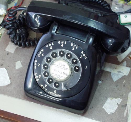
So here it is - a portable cellular rotary phone - in all it's random glory!
We've finished the ringer circuit! View it here.
Want to buy one?
Find the phone on Ebay -
Where do you even buy a rotary phone these days? Oddly enough, there are quite a few phones on Froogle that had push buttons within the faux rotary face. That won't do.
How about the Senior Store! No really - they sell rotary phones for seniors. Cool, but $49.95 is a bit too much. BoldOldPhones is also another great resource for rotary phones. They even have colors!
Where else to look? Ebay of course! You can find anything! There are quite a few people selling rotarys of different qualities and ages on Ebay. Most are ~$20. We got our 1957 'Automatic Electric Company' rotary phone for $10 + $8 in shipping. Not too shabby.
Cool!
Whoops. The auction alluded to the 'original tone ringer' which looks like they meant the phone was upgraded. Oh well - I'll have to find another rotary with the old bell type ringer for Port-O-Rotary v2.
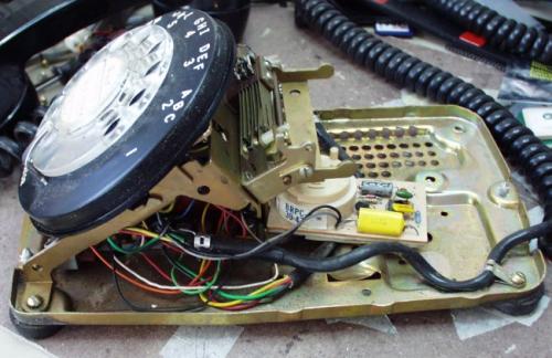
What a mess of wires!
The phone was a bit dirty (not bad for nearly 50 years of age) but was easily disassembled.
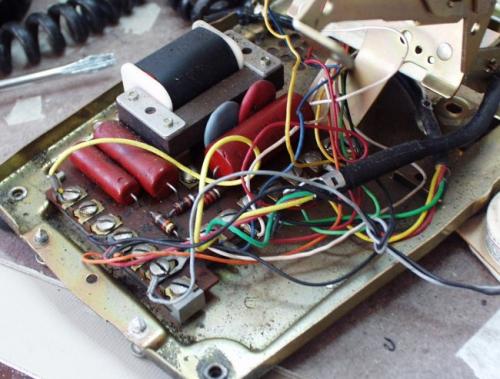
Now those are some components! Time to replace them with technology of the 21st century. I tore the phone apart, wiped everything down with some warm water and elbow grease. On a side note, I think the previous owner was a smoker...
Rotary Decoding -
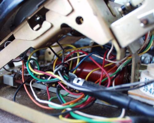
Let's take a look at the actual rotary and how it functions.
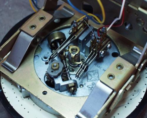
Here's a couple photos of the rotary element up close to help you get an idea of what is going on. Basically, the entire system is just the opening and closing of switches.
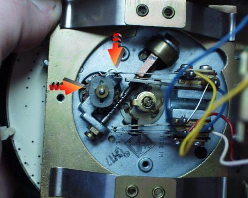
When you twist the rotary around, nothing much happens. When you let the rotary go, the dial starts turning back to its original position. As it does this, the grey oblong wheel spins once for every two numbers. Two numbers? That seems silly. Actually, it makes it very easy. This picture is about as good as it gets and it's still not very good. You can see the top two paddles slightly further apart. There seems to be some nice liquid gel that is protecting the paddles so they never actually have an visible open space. But if you hook up a resistance meter, sure nuf, the thing is toggling on/off. Ok, that seems easy enough.
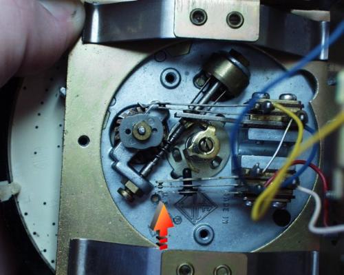
Now this is another important picture. This is the rotary in the finished, or non-turning position. Take a look at the bottom three paddles. When the dial has returned to the finished state, the center brass column exhorts pressure on the black pin, opening the very bottom paddle. Thus, you can tell when the rotary is finished spinning! Ohhh, this is almost too easy! Now we just need a PIC to take a look at the on/off clicks.
Here we have an 18 pin development board with the 16F88 loaded onto it. I used the Bloader/Screamer boot loader pair.
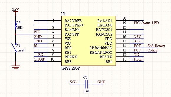
Here are the connections to the various pins. This is a SSOP version that is being design into another PCB but just imagine it's a 18-pin DIP. No crystal, uses the internal 8MHz because at 3.8V on a non-16LF88 part, we'd better be careful.
The minimum operating voltage for the 16F88 is 4V but I was able to run it fine at 3.8V.
'End_Rotary' is connected to the lower paddle. 'Rotary' is connected to the upper paddle. 'Hook' is connected to a similar paddle within the upper rotary mechanism that tells you when the phone is lifted off the hook or not - it's surprising simple... There are two complimentary paddles (one for the hook circuit and one for the rotary circuit) that are connected to ground. PORT B on the 16F88 have internal 10K pull-up resistors. Turn them on and you've almost got the hardware wired up!
So with the internal pull-ups on, 'End_Rotary' will see a '1' while the user has activated a number and the rotary is returning - and a '0' when the rotary is in the normal sitting position.
'Rotary' will see a '0' every time a number passes by and a '1' every other time. Actually, it adds 1 extra click at the end of every dialed number, 7 clicks when rotating from '6', 2 clicks from '1' and 11 clicks when rotating from '0'. This will all be taken care of in software.
'Hook' will see a '1' when the phone is on the hook and a '0' when the user is using the phone.
Now for some firmware!
while(END_ROTARY == 0 && HOOK == 1)
{//Now count how many times the mechnical switch toggles
while(ROTARY == 1) if(END_ROTARY == 1 || HOOK == 0) break;
delay_ms(10); //Wait for switch to debounce
while(ROTARY == 0) if(END_ROTARY == 1 || HOOK == 0) break;
delay_ms(10); //Wait for switch to debounce
dialed_number++;}
This is the loop that decodes the clicks from dialing. We always need to be on the look out for when the user hangs up the phone so there are a lot of conditionals. I guess you could call it a state machine, but it's just C code to me.
We wait for the switch to open and close. Throw in some delays to ignore the bouncing and we've got it! Once END_ROTARY = 1 dialed_number will contain the number dialed + 1 (remember the extra click on everything?).
dialed_number--; //Rotary always has one extra closure that must be taken off
if (dialed_number == 10) dialed_number = 0; //Correct for operator call
if (dialed_number < 10) printf("%d", dialed_number);
else printf("!", 0); //Error condition
if (counter == 2 || counter == 5) printf("-", 0); //Fancy - easier to read
Here we are manipulating the dialed number (subtracting 1) and the zero/operator case. Then we clean things up a bit for printing.
You can download the firmware here:
It works very well! You dial 3035551234 and hyperterminal will spit back "303-555-1234". The firmware took a surprisingly small amount of time. Who know this old hardware would mate so nicely with something 50 years later?
GM862 Interface -
Now let's talk about the actual cell phone part of things. The GM862 is a fantastic fit for this project. It can be directly connected to by the PIC running at 3.8V and the PIC can control the phone dialing by simple AT commands.
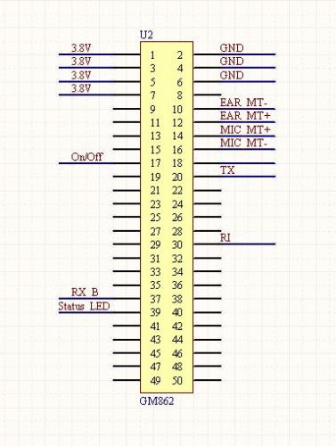
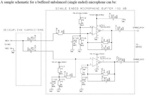
Here are the pin connections to the GM862. If you read into the 1000+ pages of datasheet for the GM862, it can be a little discouraging. The designers provide/recommend all sorts of circuitry to interface an electret microphone and speaker to the module. I had no idea what I was up against.
Ugh. And I didn't even know the characteristics of the 50 year old phone handset. What to do?
Well the speaker dry-tested at 60Ohm. That seems reasonable. And the datasheet states that the module can drive most small speakers directly. So I stripped the four handset wires and traced them to the speaker and mic. I hooked up the handle with the speaker attached to EAR MT +/- and phoned home. Holy smokes. I can hear me!
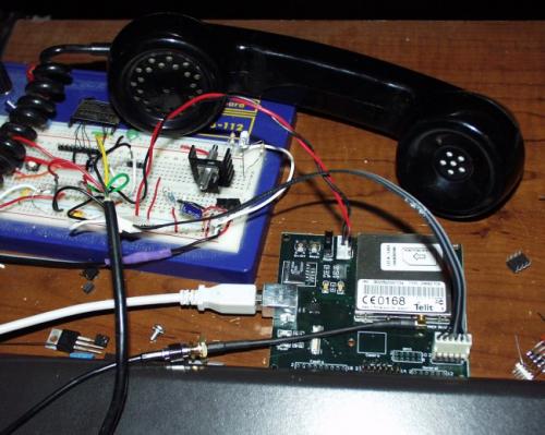
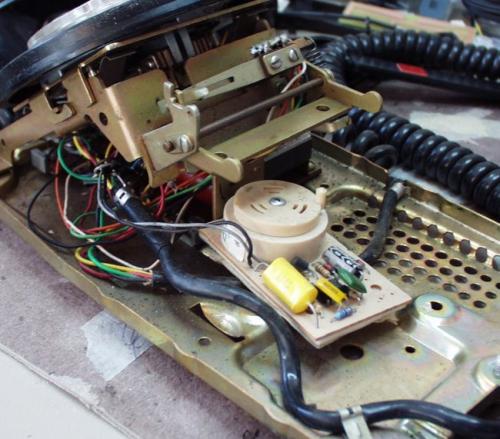
Here we have the GM862 attached to a custom breakout PCB and the handset. No kidding - it worked!
Next trick was to get the MIC kicking. I was taken back to the old Opamp days of audio. I should be able to amplify whatever is coming out of the microphone and clean it up, blah blah blah. So I hooked up a simple 30 gain Opamp with a trimpot and scoped the output. Sure enough, I was getting some nasty ringing, but I could see the signal was 0-5V - I was basically railing the opamp. Ok, that's some amplification. How much does the GM862 need?
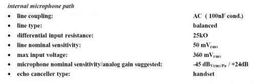
Wait a second - 360mV Peak to peak? But, that's like nothing. So I disconnected the opamp and probed the microphone on the handset directly. I biased the (what I assumed to be) electret mic with a 4.7k resistor and a 10uF electrolytic decoupling cap:
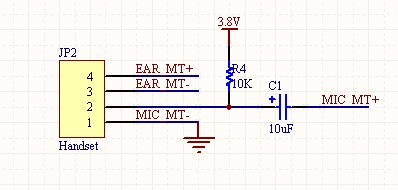
I got 300mV P-P! Yep. I circumvented an entire layout with a cap and a resistor. This just proves my theory that you should think less and wire more. While this solution has some noticeable quality issues, that's not the point - it just has to work!
So I wired up the MIC very carefully to the GM862 along with the speaker and I placed a call. It was the ugliest phone I've every seen with an antenna laid out across the room near the window, a 1950s style handset, and a bunch of wires and boards. But I called! I called my other cell phone and talked to myself, but that's besides the point... My girlfriend probably didn't want a call at midnight just so I could ask her "Guess what I'm calling from?"
Battery Power -
The GM862 needs 3.8V at a peak of 2A. This is really screwy because most linear regulators can't handle these peaks and give off a lot of heat when regulating 10-15V from a wall wart down to 3.8V. Besides, the entire thing was supposed to be portable. Time for batteries!
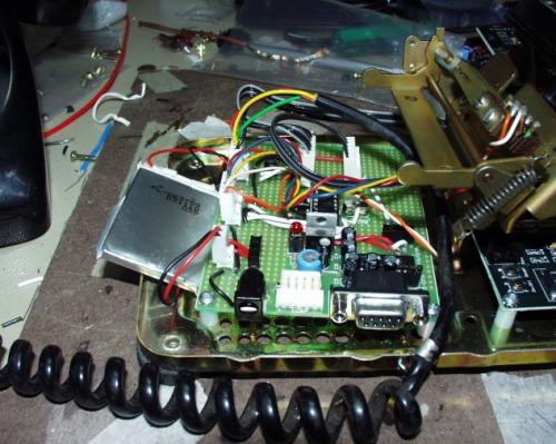
You can see here, I have a Polymer Lithium Ion battery off to the left. These batteries are extremely small, light weight, juicy (this one is 750mA), and run at 3.7V. Perfect! I also have a few 2000mA cells which, in parallel, could run the phone for a good two weeks! So I run the entire system directly off the battery with no voltage regulators and no heat worries! Just a simple on/off switch and we're set to go.
We've got system powered, the rotary decoded, now all we need to do is send this decoded phone number to the GM862.
I used the PIC's onboard UART to interface both the debugging/programming and the GM862 communication. This posed a problem in that the MAX232 IC would compete with the GM862 if both RX lines were tied together (GM862 and MAX232 would both try to drive this line high or low - it's called bus contention and could fry stuff). So I isolated the RX bus with a toggle switch connected to the PIC - one position for the MAX232, one for the GM862.
//Once we are here, we have the number, time to send it to the cell phone
printf(" atd ", 0);
for(counter = 0; counter < 10 ; counter++)
putc(phone_number[counter]);
putc(';');
putc(' '); //The number should now call
while(HOOK == 1); //Wait for user to complete call
printf("ath ", 0);We've got the number, all the PIC does is send a serial string to the GM862. ' ' is the C command for return. So the PIC hits enter, and then sends 'atd ##########' and then hits return again. If received correctly, the GM862 will dial the number and place the call. The PIC doesn't check anything. So if the GM862 is not connected to the network, or can't get a signal, or just plain off, the PIC doesn't know and assumes all is well. This type of error detection/correction is simple enough, but I left it out for simplicity's sake.
Once the PIC detects the phone is back on the hook (HOOK == 1), the PIC sends the 'ath' command to hang up and hits enter. The GM862 should kill the call and all should be well...
Boxing it up -
Now we've got to get this thing into its new home!
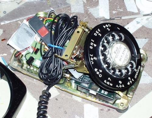
The Tri-band Cellular Antenna has 10' of RG174 cable that could be trimmed off, but I left the cable intact for future projects. I am going to try an etched antenna with a short 4" cable very soon.
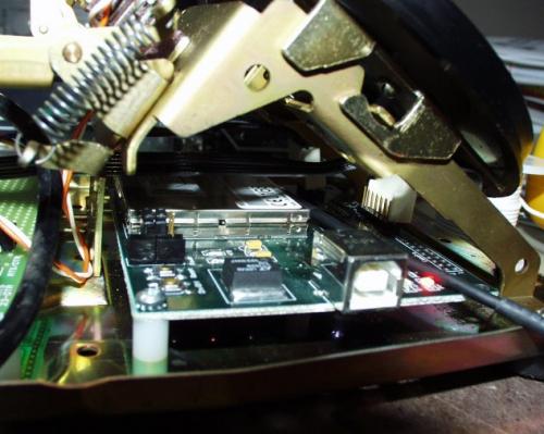
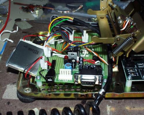
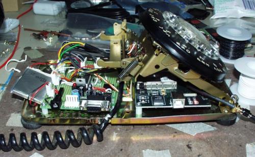
There's the GM862 breakout jammed underneath the rotary. I used two 6-pin ribbon cables to make the connections to the PIC board.
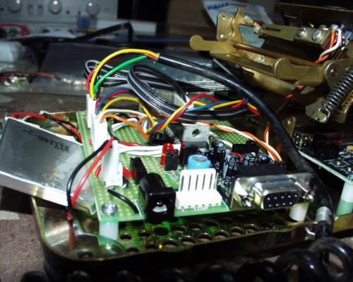
There's the PIC board and battery.
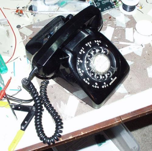
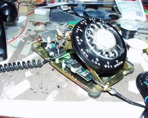
The final product!
The functionality is there and it only took a days worth of work! The phone can dial out and call any number you want. It's really a trip. But the sound is a little scratchy (go figure), and the dialing doesn't always work. I think there is a bug in the firmware and a problem with my cellular plan - it always seems to be on roaming. Once I get a good cell connection, things should improve dramatically.
The next version calls for a single PCBs with a smaller, PCB antenna. This will make room for the large bell ringer. The next version has GOT to ring!
As usual, let us know what you think.
-NES
January, 17th 2005
We've finished the ringer circuit! View it here.
Custom units are now available for sale.
Is there a parts/equipment list for this project? I've read through this tutorial several times but want to be sure I have everything I need. I want to order everything at once so I can be sure not to mis anything.
Is there any special/expensive equipment I would need?
Actually most old phones used carbon granule microphone capsules. They needed a bias voltage to operate (being more like a variable resistance than anything else) and were inherently a little noisy. Also in prolonged use the carbon granules used to pack down and the microphone would produce less and less signal (the fix for which is to whack the handset hard on something solid to break up the packed granules... needless to say its anti-social to do this during a call!). Given that most people will want the bell and dial aesthetic more than the crappy microphone, I'd replace it with a nice, well behaved dynamic or electret module.
Great project though. Well done.
This is just So-Cool !
I will put one on my Christmas list.
This is such an awesome project. I have created something similar. I used a (power hungry) raspberry pi, Python script and an old Nokia 6301. I enhanced the phone with an LCD display. Unfortunately there wasn't room in the case for the ringer I built. But it doesn't matter as the Nokia has a realistic ring tone! Everyone loves it, although the battery life is a bit short with 6xAA. I have also added a programmable phone book which makes dialling a lot quicker. My next version will use a PIC as per this project and a new/old red phone :)
Uhmm.. about Port-O-Rotary, do you have a kit to connect the old Port-O-Rotary to modern land lines... they provide less voltage for ringer, and calls usually drop if you connect one of those phones to new land lines. A circuit to deliver the proper voltaje from a POT should be cool
We sadly don't have a kit for that, as our Port-o-Rotary phones were designed to be wireless. However, you may want to check out Instructables. I seem to remember seeing a hack on there for modifying a port-o-rotary to modern land line connections.
This is awesome. This idea came to me a couple days ago, only my idea was a little different.
My idea is to install a raspberry pi in the bottom and attach a Bluetooth receiver. I would like to be able to use the handset to make or receive calls. Maybe I could even use the dial as a speed dial. Example: I pick up the receiver which activates a program in the Pi, I dial #1 and the Pi sends the proper signal to call the person in position 1 in my phones speed dial program.. I don't know if this can be done but I don't think I'm the man for the job after reading this tutorial..I would certainly buy it though!
What you're describing is the Port-O-Rotary Bluetooth. See https://www.sparkfun.com/products/9803
Has anyone tried using a rotary phone with the built in indicator light on it? Maybe having a way to toggle the ringer and use just the light whenever you choose. Kinda like silent/vibrate mode on a normal cell phone. Or even put some type of vibrating module inside the phone for jokes.lol
Rotary phone with indicator light on it.
http://postimage.org/image/1ids7bysk/
"When the dial has returned to the finished state, the center brass column |||exhorts||| pressure on the black pin"
Come on, pin!!! You know you wanna help us out!
Hi, I'm a beginner in tinkering with electronics and I found a few rotary phones fully functional being thrown out so I decide hey I want to do something cool with them. I got a few ideas and searched google and found your project. It's very interesting and I wanted to take it a step further, I wanted to use a rotary phone as a house phone, I would need to make it digital but also I want to make the handset wireless so that you must return it to the base to hang up and dial at the base but having the freedom to walk and talk. I was thinking of using bluetooth, any suggestions?
Ya'll are currently working on my beloved port-o-rotary. I can't wait to get it back. I'm even wondering if there were any updates to the insides since I first purchased in back in '08.
Only time will tell. And once again, the Sparkfun team rocks for taking the time to fix my phone!
-Chris
You would be best to email techsupport@sparkfun.com.
A small optimization: I think you could have done this without the PIC -- the GM862 has quite a few GPIO pins, and is programmable (in Python), so you could probably have done the rotary sensing etc directly from the GM862.
Also, in the UK version of these phones, I think the microphone was resistive, do you think that's what you've got here? I'm not that hot on analog stuff myself but I think your circuit would work with a resistive microphone.
Totally! Is this no longer common knowledge? Maybe it's a codger vs. youngster thing (already? I'm only 45!) but when I was a kid, the reason we liked playing with old phones (real Western Electric ones) was that they all used carbon mikes, so all you have to do is hook the earphone, mike, and a battery or two (dry cells last forever and have nice binding posts on top) and you can hear what's being said. No active components at all. But that means the mike on its own has NO output.