
Robot Building!
Some people (like my brother) have seen the robots on TV (Battlebots, etc.) and have suddenly gotten a 'bug' to build a robot. Not me. I've been putting off building a robot for years now. But that all changed when my brother pointed me towards the Robothon robotics competition (www.robothon.com) held in Seattle every year. Time to get building....
I rarely endorse or recommend books/companies. But I am going to make huge concessions in this tutorial.
If you want to know the nitty gritty 'how to' of robotics, take a look at Dave Cook's book Intermediate Robot Building.
If you need a quick and easy chassis, checkout Pololu's disc chassis with gear boxes and truck tires.
Get to it!:
Page 1 : Main Page
Page 2 : Assembling the Chassis
Page 3 : Soldering the Motors
Page 4 : PWMing via Timer2 ISR
Page 5 : Final PCB BotSchematics: Main board, Motor Controller
This tutorial will shoot you through the basics of assembling a Dirty Bot: a small robot controlled by a PIC 16F88 using a Pololu chassis and Pulse Width Modulation techniques to control the motor speeds.
Some people (like my brother) have seen the robots on TV (Battlebots, etc.) and have suddenly gotten a 'bug' to build a robot. Not me. I've been putting off building a robot for years now. But that all changed when my brother pointed me towards the Robothon robotics competition (www.robothon.com) held in Seattle every year. Time to get building....
I rarely endorse or recommend books/companies. But I am going to make huge concessions in this tutorial.
If you want to know the nitty gritty 'how to' of robotics, take a look at Dave Cook's book Intermediate Robot Building.
If you need a quick and easy chassis, checkout Pololu's disc chassis with gear boxes and truck tires.
Get to it!:
Page 1 : Main Page
Page 2 : Assembling the Chassis
Page 3 : Soldering the Motors
Page 4 : PWMing via Timer2 ISR
Page 5 : Final PCB BotSchematics: Main board, Motor Controller
Let's face it, I am not a mechanical person. I can't tell you a worm gear from a fly wheel, and I certainly can't build a gear box. There are a huge number of DC motors out there. The really cheap ones (<$0.50) work great, but spin very fast with not much torque. That's why we went with a Pololu setup: http://www.pololu.com. The Mazer uses a 203:1 gear ratio which means for every 203 turns of the super fast motors, the wheels turn once. Also, the thing that attaches your wheels to your motors (called shaft couplers) can be very tricky to make. Pololu makes it easy with the Tamiya Twin-Motor gear box and Truck wheels.
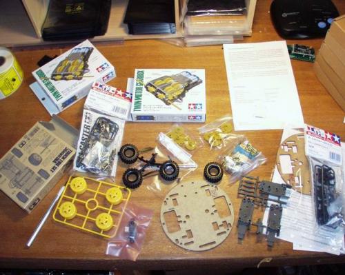
I am a kid in a candy store!
I was superbly happy with the setup. It's like building a model airplane but without needing all the patience or talent! Cutting out the parts, reading the instructions (sort of). It took about an hour to get the chassis assembled. Don't be confused by the picture, I bought enough parts to build two complete robots. One for my brother and one for me. Comon' sumo wars!
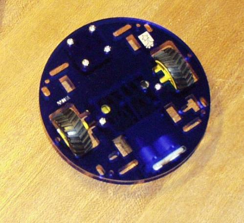
The bottom side of the Pololu standard chassis
Not bad for an hour's worth of work! Anything else would have taken me days. And I don't build mechanical stuff, I just like doing the electronics end of things.
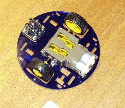
Top side
I imagine there's a way to get rid of all the brown protection paper that covers the plastic, but I'm far too lazy. Besides... It's time to add the electronics!
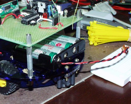
6V Battery Pack
Pololu recommends driving the motors with a 3V-6V battery pack. The higher the voltage, the higher the torque - so we decided to go with a AA 6V pack! Besides, we had a ton of 1800mAh Nickel Metal Hydrides (NiMH) sitting around. Make sure you attach a polarized connector to the pack to prevent you from connecting the pack in reverse to your main board (SparkFun, right?).
Another idea: Mark on your batteries with sharpie. The date, a nickname, anything. This way you can tell what batteries have lived together and how long they have been in use. I've got some batteries from 2 years ago that are rather short lived and I'd hate to mix them up with my good ones. Otherwise you may be hard-pressed to tell the difference between the good, the bad, and the leaky.
The chassis from Pololu is also a bit motor heavy and will tip, nose up, on its own. To prevent this from happening we positioned the battery pack towards the caster end of the bot. A stick'um piece of Velcro would have been a nice addition as well to hold the pack in place, but I am still trying to figure out where to place the batteries for the best weight distribution.
Time for motors!
Some people (like my brother) have seen the robots on TV (Battlebots, etc.) and have suddenly gotten a 'bug' to build a robot. Not me. I've been putting off building a robot for years now. But that all changed when my brother pointed me towards the Robothon robotics competition (www.robothon.com) held in Seattle every year. Time to get building....
I rarely endorse or recommend books/companies. But I am going to make huge concessions in this tutorial.
If you want to know the nitty gritty 'how to' of robotics, take a look at Dave Cook's book Intermediate Robot Building.
If you need a quick and easy chassis, checkout Pololu's disc chassis with gear boxes and truck tires.
Get to it!:
Page 1 : Main Page
Page 2 : Assembling the Chassis
Page 3 : Soldering the Motors
Page 4 : PWMing via Timer2 ISR
Page 5 : Final PCB BotSchematics: Main board, Motor Controller
Next was the electrical connections to the motors.
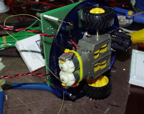
Here you can see the dual DC motors tight and happy in their gear boxes. Pololu recommends soldering a .1uF cap on the motors to reduce electromagnetic emissions (http://www.pololu.com/projects/prj0001/). I've also had a friend who plays with RC cars recommend the same thing. I had some 50V .1uF Mylar caps sitting around. Solder on the cap and the wires to the flimsy connectors on the motors.
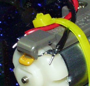
If you tear off the lead to the motor, you're screwed. So I used two skinny cable ties to keep the wires in place - it's very robust. If I ever need to pull the motors, I'll have to cut the ties and re-strap it. No big worries here.
So we've got the chassis, motor assembly, and battery. Now we need some control of these motors.
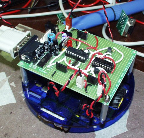
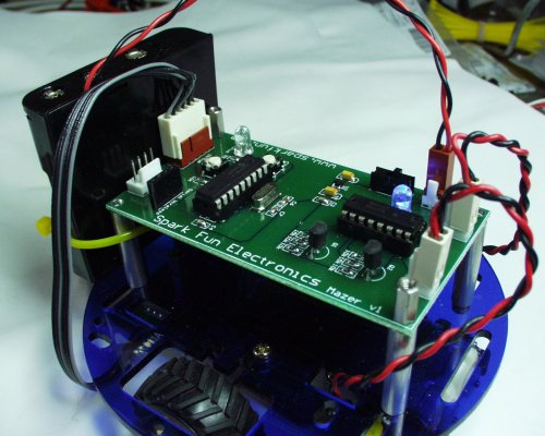
The PIC-P18 fitting nicely on top of the chassis
Here we've got the PIC-P18 development board that has been dissected quite a bit. The main chip is the 16F88 running the Bloader boot loading system with a pull-up resistor and reset switch installed. The battery is attached near the power jack and is controlled by a power switch. There are a couple rows of black female SIP connectors (3 of them, 4 holes wide) around the board that are there from a previous project - they don't serve a purpose here. I kept the MAX232 circuit intact for communication to my Tablet PC for downloading of new firmware via Bloader. Finally, you can see the magical H-Bridge chip (L293DNE Datasheet) with a couple 2N3904 transistors. The PIC just talks to the H-Bridge, while the H-Bridge is the chip actually responsible for driving the motors.
If you're not quite up to building this H-Bridge circuit from scratch, take a look at Pololu's Serial Motor Controller. It's a fully contained solution, all you have to do is speak to it via serial commands. The unit is based around the Sanyo LB1836 DC motor driver. Much like the L293DNE, but it comes in a handy surface mount package. The LB1836 can handle up to 1A per motor and has an internal thermal shutdown feature that keeps it from destroying itself if things get toasty.
BTW: If you want to know how the big boys control the 150lbs. kill-you-instantly robots, read Mr. Cook's book Intermediate Robot Building. It will fill you in on all sorts of high-voltage, high-power drivers using MOSFETs and the likes. I highly recommend the book - Mr. Cook is an easy author to read.
So we need to control the H-Bridge. Get the full PDF schematic here. Here's a snippet of the schematic:
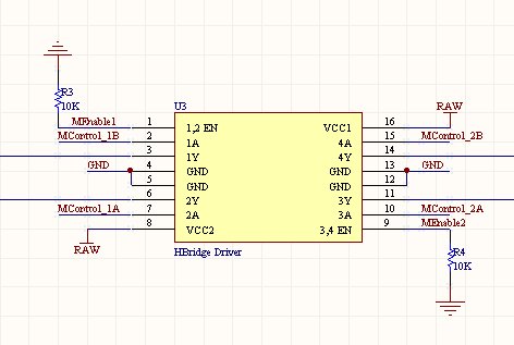
The H-Bridge and its various connections. Things to note:
-
Tie both enable pins to ground through separate resistors. This insures the motors will not turn while the PIC is not actively controlling the enable pins - translation: the bot will not spin out of control while the PIC is in reset mode.
-
Be sure to connect VCC 1&2 of the H-Bridge directly to your power source. The motors use a good bit of current (0.5-1A each) and you don't want to limit their appetite in any way (no diodes, no voltage regulators).
The control pins (MControl 1A, 1B, 2A, 2B) are the logic interface pins. The PIC attaches to the H-Bridge through these pins. To get the left motor to go forward, MControl_1B must be logic high (5V) and MControl_1A must be low (0V). Summarized:
-
Left Motor Forward : MC1B(H), MC1A(L)
-
Left Motor Reverse : MC1B(L), MC1A(H)
-
Right Motor Forward : MC2B(H), MC2A(L)
-
Right Motor Reverse : MC2B(L), MC2A(H)
There are ways to brake the motors and coast and stuff (by taking both MC1B(H) and MC1A(H) for instance), but I don't need any of those. And I wanted as many pins on the 16F88 as free as possible so...
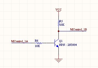
The inverter circuit
Here's the trick to control the motor direction with only one pin. When MControl_1A goes high, it forward biases the 2N3904 transistor (Q1 turns on) and MControl_1B is effectively connected to Ground (0V). So that's the 'Left Motor Forward' state. If we tell MControl_1A to go low, the transistor is left open and the MControl_1B line is pulled high by resistor R5. Thus we have the other state 'Left Motor Reverse'.
It takes a little additional wiring and parts. But what used to need four control pins now only needs two! Sweet!
So now we need the connections to the PIC 16F88. Take a look at the Main Board schematic here.
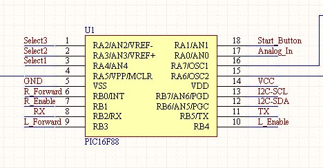
Nothing too exciting here. You can attach the H-Bridge control pins wherever you like really. Remember, VCC and RAW are two different power buses. If you attach the PIC directly to the battery pack, you are going to have some serious problems. The 6V nominal voltage on the battery pack is too high for a PIC, and the voltage spikes and sags due to the turning motors will cause havoc with the system. The PIC needs a nice regulated 5V supply.
To make matters more complicated, the LM7805 5V regulator on the PIC-P18 development board has a 1.5V voltage drop. This means you have to put in at least 6.5V to get 5V out. We are only pumping 6V max (from the battery pack) into the 5V regulator, so the PIC is going to run at 4-4.5V. It's a little dirty, but it worked just fine! On the Main Board schematic, you'll see the TPS76350 regulator we used on the PCB version of Mazer. This is a very small, surface mount 5V regulator that has something like 150mV of voltage drop. It's much smaller and much prettier.
Some people (like my brother) have seen the robots on TV (Battlebots, etc.) and have suddenly gotten a 'bug' to build a robot. Not me. I've been putting off building a robot for years now. But that all changed when my brother pointed me towards the Robothon robotics competition (www.robothon.com) held in Seattle every year. Time to get building....
I rarely endorse or recommend books/companies. But I am going to make huge concessions in this tutorial.
If you want to know the nitty gritty 'how to' of robotics, take a look at Dave Cook's book Intermediate Robot Building.
If you need a quick and easy chassis, checkout Pololu's disc chassis with gear boxes and truck tires.
Get to it!:
Page 1 : Main Page
Page 2 : Assembling the Chassis
Page 3 : Soldering the Motors
Page 4 : PWMing via Timer2 ISR
Page 5 : Final PCB BotSchematics: Main board, Motor Controller
Alrighty! So the PIC 16F88 can now drive the left motor forward/reverse (via the L_Forward pin) and turn on/off the left motor (via the L_Enable pin). Same goes for the right motor. The Pololu chassis is nice in that the wheels are situated to allow you to complete 0 degree turns. By driving the left motor forward, and the right in reverse, the bot will turn in place.
Now if you hook this setup up and tell the PIC to drive the motors forward and enable both motors, you will see a very cool little robot eat shit as it launches itself off your lab bench, and worse, into your lap.
How to alleviate this? With Pulse Width Modulation. Imagine yourself turning on and off the motors really fast. The robot will move forward, but not completely fast, not at full throttle. PWMing the motors will allow you to control the speed at which the motors turn, it's up to you to figure out at what speed and what direction.
How to setup the PWM Motor Control:
There's a few different ways to do pulse width modulation.
-
You can do it in software. That is to say, every time you go around the main loop you increment a counter. Once that counter has reached a certain amount, reset it to zero and turn on or off the motor. While this is ok in principal, there may be parts of your 'main' loop that will very in the length of time they take to complete. Translation to nerd speak: The various logic branches of main are non-deterministic. Your motors will spin at varying speeds depending on the input the bot is receiving - not really in control.
-
So then we look at hardware. The 16F88 has some PWM hardware built into it (see the CCP section of the datasheet), but it's limited to only one Pin. We need two PWM outputs for two motors.
-
So that leaves using a hardware timer interrupt. Right...
I've setup a really handy way of doing PWM for two motors using the TMR2 interrupt. Timer2 increments every time an instruction is completed, so at 20MHz (125ns), an instruction is completed every 4 clock cycles (or every 500ns). Timer2 is an 8-bit timer that rolls over from 255->0. Since the TMR2 interrupt fires every time this roll-over occurs we can expect our ISR (interrupt service routine) to happen every:
500ns/instr * 256instr = 128us
Let's put a post scalar of 8 on Timer2 so that the ISR will fire every
128us*8 = 1.024ms
I want to setup a Pulse Width Period of 30mili-seconds. Therefore, every 30th time the ISR is run, I want to restart the period (T) and I want to vary the length of (t) to vary the speed of the turning motor.
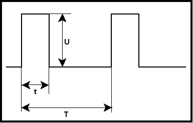
Google stolen without permission from here
Here is the ISR code written in CC5X:
if(TMR2IF) //TMR2 Overflow Interrupt
{iteration_counter++;
if(iteration_counter == 30)
{iteration_counter = 0; //~30ms pulse width
//Start your motors!
Right_Enable = 1;
Left_Enable = 1;
}
if(iteration_counter == drive_right_time) Right_Enable = 0;
if(iteration_counter == drive_left_time) Left_Enable = 0;
TMR2IF = 0; //Clear INT Flag}
Here you can see that the right motor will run until its drive_right_time variable is equal to the iteration_counter at which point it is switched off. Same goes for the left motor. No matter what, both motors are turned back on after 30 iterations or ~30ms have gone by.
Now all we have to do is load drive_right_time and drive_left_time with appropriate values and the motors should run. By experimentation, a minimal setting of 4 or 5 started the motors turning. This could vary as the pack voltage drops and the torque goes down.
Now there is some programming considerations here. If the interrupt is firing every 1.024ms, that means the PIC is doing this little ISR routine 1000 times per second which can be some serious overhead if you are running some closely timed routines. It all depends on your application. You can reduce this by increasing the prescalar and postscalar on Timer2, but there is a limit. At some point, you will start to notice that the motors are jerky or perform oddly. Strike a good balance between a high refresh rate for the motors and as few interrupts as possible.
The other routine you'll find in the source code, called motor_control, just takes input from the user and increases or decreases the motor 'on' times accordingly. It also takes care of the forward and backward considerations. It's actually a lot of fun to drive the little guy around wirelessly in my kitchen...
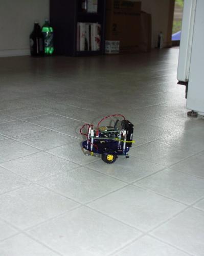
Where's the cat?
Some people (like my brother) have seen the robots on TV (Battlebots, etc.) and have suddenly gotten a 'bug' to build a robot. Not me. I've been putting off building a robot for years now. But that all changed when my brother pointed me towards the Robothon robotics competition (www.robothon.com) held in Seattle every year. Time to get building....
I rarely endorse or recommend books/companies. But I am going to make huge concessions in this tutorial.
If you want to know the nitty gritty 'how to' of robotics, take a look at Dave Cook's book Intermediate Robot Building.
If you need a quick and easy chassis, checkout Pololu's disc chassis with gear boxes and truck tires.
Get to it!:
Page 1 : Main Page
Page 2 : Assembling the Chassis
Page 3 : Soldering the Motors
Page 4 : PWMing via Timer2 ISR
Page 5 : Final PCB BotSchematics: Main board, Motor Controller
Now what?
After wiring up the 'proof of concept' bot, we of course had to go from a through-hole prototype to a PCB!
Before
After...
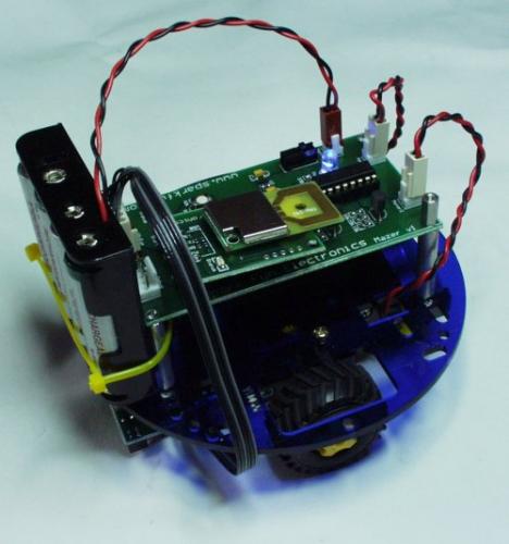
Mazer v1 with the SMiRF wireless link plugged in
What's the SMiRF?
The SMiRF is the wireless link we created because of a couple projects that cropped up. Mainly, I couldn't run the tests on Mazer with the serial cable attached. And while I could implement the RF-24G unit into the Mazer main board, I didn't want to dedicate the resources or the pins of the main controller to handle the interface. So we created a 'black box' of sorts to handle the serial stuff. All you do is setup the PIC to output serial communications at 9600bps and connect the TX and RX pins correctly to your microcontroller. It can be powered from 3-10V and requires only 20mA for duplex (both TX and RX), serial communication.
We can even boot load over the wireless link! Just imagine programming your robot on the fly without ever needing to touch it... Nifty!
It works great! And you can hassle your cat by driving the robot 'round the kitchen....
Ant chance you would have some samples or tutorial for the AtMega168 for our little friend here?
I have ordered all the parts and am intending to use the AtMega168 and a 2.4 MhZ wireless cam to build a security drone.
Also I would love to publish a tutorial here if that is at all possible.
Just curious as to why you chose a pic uC when most seem to be going to AtMega chips?
PICs are what I first used/learned. The 16F84A was expensive, and painful to program, but that's what all the tutorials and books referred to circa 2002. I've since started drinking the Atmel koolaid and very much like the ATmega line.