
Audiophile Heaven
Over the last year or so, we?ve received emails asking for 6DOF sensor boards and controller boards to be made available independent from each other. So when we recently revised the 6DOF v4, we decided to make the separate boards as stand-alone as possible.
So what? What do you do with them apart? Well, the sensor board is pretty obvious: it?s a bunch of sensors, so you sense things with it. But the controller board?you can do just about anything with it. It?s not limited to sensing applications by any means. It?s an LPC2138 with everything it needs to run (plus Bluetooth? connection onboard), free compiler, source code, all in a tight little package ready to go. Not that we don?t like Olimex. To the contrary, we love Olimex. But for the example I?m about to present, I needed something smaller and simpler than the LPC2138 dev board.
Now to the meaty bits.
One of my extra curricular pursuits is tube audio. Not guitar amps (though I?ll likely build one of those sooner or later), but stereo amps. I just think they sound great. And tubes pretty much rule as far as I?m concerned. But before I get too far into this, let me address some of the inevitable questions/comments that my audience may have:
-
Yes, you can still buy tubes. Many places, many types.
-
Yes, solid state tends to be more linear. But sound amplification is not necessarily about linearity. It?s about the sound and what?s pleasing to the ear. Solid state technology certainly has its place, but I don?t want it in my audio path.
-
Yes, I could almost certainly achieve the same sound for less money and effort if I used solid state. That would be cheating. And it wouldn?t be nearly as cool.
Here?s what I?m working on:
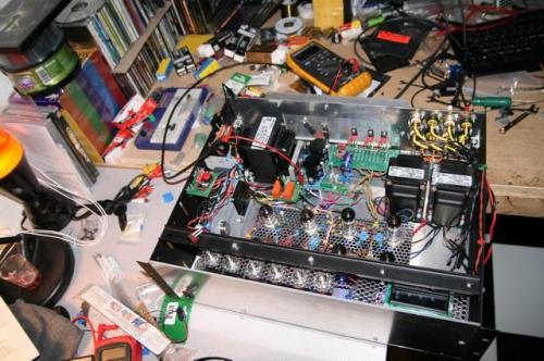
Where's Waldo? Ok stop. There is no Waldo.
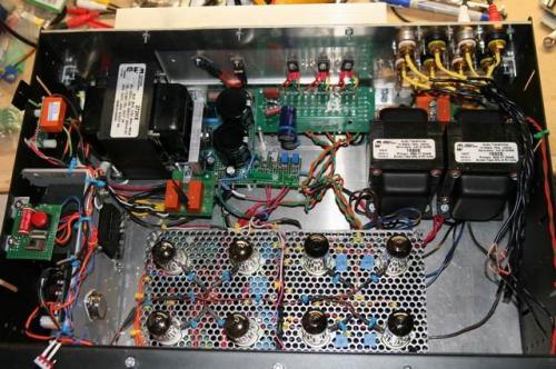
This is the first of many tube amps I hope to build. The high-voltage and heaters transformer is in the upper left. The regulator circuits, both for the high voltage (320V) and heaters for the tubes (6.3V) are at the top middle of the picture, with the hot bits mounted on a heat sink. The audio transformers are top and right. There?s also a 5V Condor linear supply at the bottom left that runs the control system (more on that in a bit). The tubes are, right to left, (4) EL84s in push-pull ultra linear configuration, (2) 6922s as a gain stage and concertina phase splitter, and (2) 12AX7s as the input section with bass and treble boost/cut. It makes about 12W per channel, and there?s no global negative feedback. It sounds like a million bucks.
So what?s the 6DOF controller board for? Tubes run at high voltages. Coincidentally, I?m afraid of dying by electrocution. When something fails in a high voltage circuit it?s not usually a trivial event. And I?ve had a few failures that served as motivation for installing the control system that I?m going to talk about.
Let me say a little something about tube circuits and safety. When there?s power to the circuit, I don?t put my hands in the chassis. Ever. It only takes one absent-minded moment to kill a guy working on this stuff, so I choose not to take any chances. I?ll set up my meters where I want them, make sure I?m not going to be messing with any of the leads by placing them carefully, and power up slowly with a variac while watching the voltages. Or, at least, I power up that way until I know the circuit is stable. When I power down, I disconnect from line voltage and watch all the meters go down before I touch anything. Simple rules to follow. The guy that doesn?t follow them is the guy that?s going to win a Darwin award.
Here?s the basic topology of the amplifier power supplies. As I mentioned, there?s a 5V supply that serves the control system and supporting electronics. In theory, that one?s always on. Then there?s the transformer that supplies the heater voltage and the high voltage. That transformer is switched on by relay, coil current for which is supplied from the 5V. The high voltage is also switched on by a pair of relays (2 to effectively raise the relay?s voltage rating) on the ground line to the transformer. So nothing can be on if the 5V supply isn?t on first, and the high voltage can?t be on until the heaters are on first. Cold tubes don?t conduct, so you have to run the heaters for a minute or so before applying high voltage.
All of the difficulties I?ve had with this design revolve around the high voltage regulator, which supplies 320V at 200mA. I didn?t have to do it that way. There are plenty of designs that don?t regulate the high voltage; I just didn?t want any 60Hz in the audio. Before I installed the control system, my only means of a quick shut-off was a switch on the variac that I run the thing on. It worked well enough to keep me alive, but it wasn?t fast enough to save my nerves. Nor was it particularly helpful in sorting out what failed in the first place because it allowed enough time for everything in the circuit to tank before I could shut it off. And it would send some crazy-loud 60Hz to the speakers that served to freak me out to biblical proportions.
The first order of business was to get the speakers off-line during power up. I set up the transformer outputs on relays and dummy loads. The relays are manually actuated with a switch, but it would be a simple thing to do to set them up on the control system to come on when the High voltage stabilizes. The picture shows not very well at all how I jammed them in there.
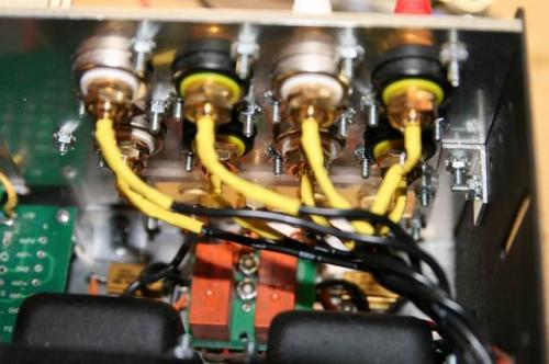
The two orange guys are the relays, and the big fuzzy gold-looking resistors to the left and right are the dummy loads. It?s a bad thing to run a tube amp without a load. And while it?s unlikely that any audio will be going through the thing during power up, you never know. Better to be safe.
Now on to the main event. I needed to set up the control system to shut the high voltage off in the event of a failure, so I have to monitor the 320V. That?s simple enough: just set up a resistor divider to scale it down and monitor the voltage with the 6DOF controller board. Then put a transistor inline with the coil current for the transformer. If the voltage goes too high, set one line on the controller board to interrupt the coil current by shutting off the transistor. The code then goes into an endless while loop to keep it off.
But fear and paranoia are the co-mothers of possibly needlessly complicated inventions, yes? I?ve gotten pretty good at code, but I?m not likely to trust my life to it. The last thing I need is for some unforeseen feedback mechanism to cause the controller board to reset and re-energize the circuit. With my luck it would start to oscillate, send me back in time to fight dinosaurs, maybe zombies?you just never can tell. Anyway, to keep my bacon out of the fire, I send the coil current through another small relay so the thing can?t be actuated without somebody manually pushing a button. In fact, the big red one you see here.
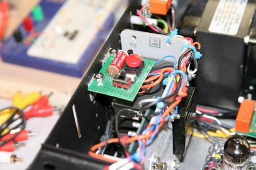
Does this look like a hack? You bet. A lot of this got put together with parts from the local electronics surplus store.
I had a few extra lines on the controller board, so I?m monitoring a few more things, just ?cuz I can. Specifically, I monitor the bias points on the EL84 output tubes. Bad bias makes for hum in your output, so it?s worth watching. Then I hooked up one of our serial LCDs to the controller board so I could actively watch. Have a look at the next few pics.
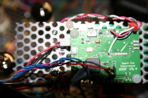
The picture above shows the controller board (it?s a v3, not a v4 ? that?s what I had lying around) mounted to the back of the plate that the serial LCD is mounted. The Bluetooth? connection is removed for this application.
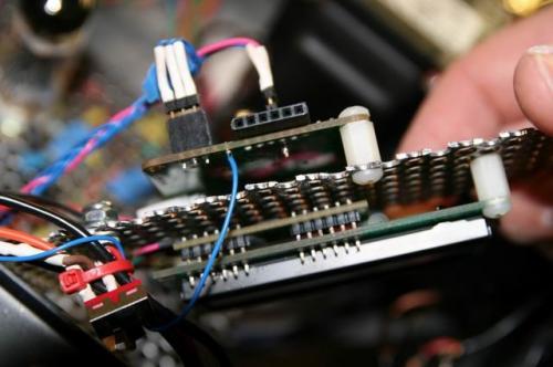
This picture (above) shows a side view of the controller board and the LCD mounting.
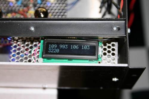
Mounted to the chassis and running. I didn?t have floating point in the printf function I was using, so no decimals. The top four numbers are the output tubes, but they?re not quite warmed up yet (they?ll all be 11V when they?re warm). They each have 3 significant digits, so we?re seeing 10.9V, 9.93V, 10.6V and 10.3V. The bottom number is the high voltage, has four significant digits and it?s reading 322.0V. My Fluke meter says that my accuracy is within 0.5V, and that?s close enough for me. The numbers displayed are averaged and refreshed every second, but the shut-off condition is from sample to sample and the loop is microseconds. If any given sample of the high voltage is 330V or greater, the whole audio section goes off. Sometimes shutting off the fluorescent light on my workbench will trip it, too. I must have finally got the regulator design right, though, because it hasn?t tripped due to a true failure.
Now for some eye candy. This is SparkFun, after all. We love our blinky things.
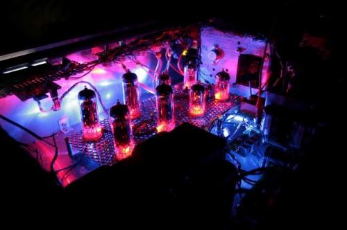
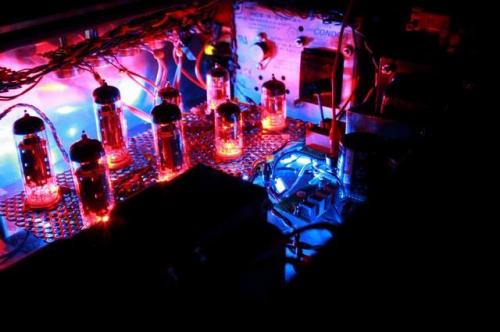
OK, tube amps don?t normally look like that. I?ve installed blue LEDs under the main mounting plates that come on with the heater voltage, and I?ve installed a red LED at the base of each tube that comes on with the high voltage. The effect is pretty amusing if nothing else.
As of the time of this writing, this amplifier has been sent off to my pal Dave in Virginia. He?s going to give it a front end like no other, with a web interface, automated controls and streaming audio over WiFi. In the meantime, a new design is on the table that uses EL34s for the output section. That should give us an output of close to 50W. And yes, it will still have all the LEDs. Maybe some lasers, too.
Pete (dokter at sparkfun.com)
Some guitarist's swear that a tube amplifier is the best country amp. I have a fender twin reverb. I hope to see the post on the amplifier soon!
FYI, I have a KNIGHT amplifier that runs a pair of EL84s (Actually, 7189s) push/pull at 400V to total 20Watts.