
SMD How To - 2
Getting X onto board Y
First, start by getting some SMD device you'd like to solder. 0603 sized components are easy with a little practice. SOT23 packages are relatively large and are common with voltage regulators. SOIC packages are also a really good place to start as well because the pitch is large and the connections are easy to inspect.
Example video showing the soldering of a SOIC IC :
<
p align="center">
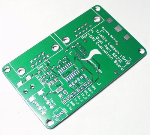
Here is the board we are going to demo on. It's a very simple 3.3V Lassen iQ GPS serial to RS232 serial breakout board. We will show how to solder the MAX3232 SOIC 16 IC.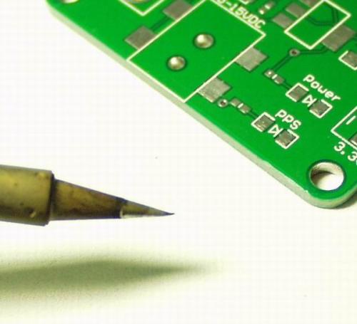
A shiny tip is a happy tip. No really. ALWAYS clean your tip. Every time you pull the iron out of the holding stand, swipe it quick on the WET sponge. Get off your ass and wet the sponge before you start. If you don't the iron won't heat correctly and the tip will be toast in a day.
A small solder tip is recommended but not required. The important thing about your iron is not getting some microscopic tip, but how evenly the heating is. A soldering iron that does not have a temperature control is not acceptable. That $10 iron that you got in your freshman engineering kit is completely worthless. However, you do not need to spend more than ~$80 for a good iron these days. I touched a $500 Metcal once, but they're really overkill for 99% of soldering. Get a good, variable temperature iron from anyone who will also sell you replacement tips. Tips wear out, and you'll be really mad if you've got a perfectly good iron but no where to get a $10 replacement tip.
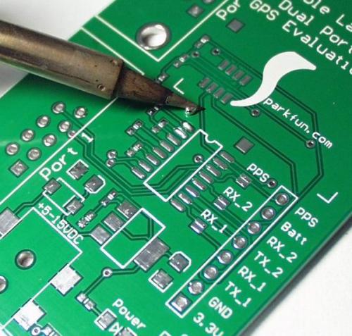
There is no magic here. Add solder to the first pad on the footprint making it dome a bit.
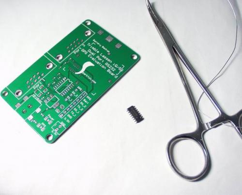
Now take your package with hemostats in your off-hand. Heat the domed pad with the soldering iron, liquefying the solder on that one pad.
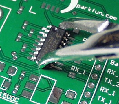
Slide the component into place and you heat the domed pad. You'll need to orient the package so that the other pins line up with their respective pads.
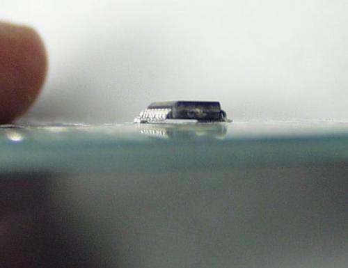
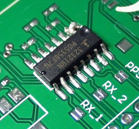
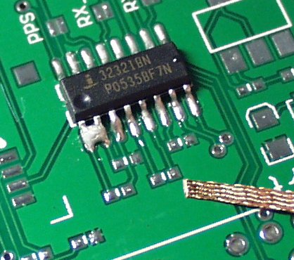
Here's my first attempt at soldering. I haven't soldered in about a year so I'm a bit rusty. I accidentally domed two pads. When I tacked the chip down, I didn't seat it all the way. Make sure the IC and as flat against the PCB as possible. This will help prevent open disconnects (nearly as bad as a jumper and more difficult to detect).
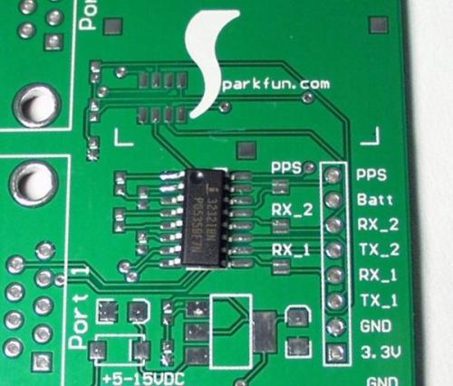
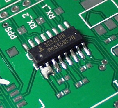
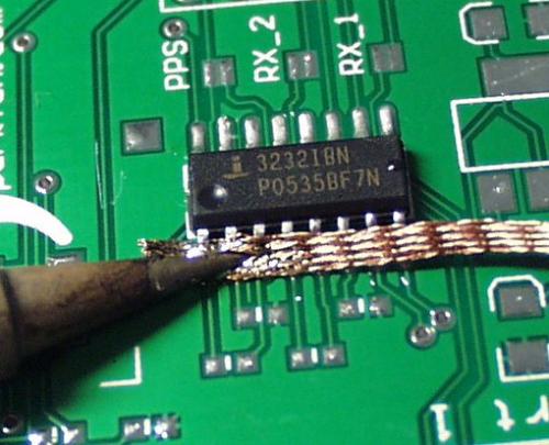
This is the second attempt, IC is flat against the PCB, but now you see the theta is tweaked a bit. Could you solder the IC successfully with this placement? Yes, of course. But as the packages get larger and the pin counts go up, your alignment has to improve as well. Do the best you can with 2 to 3 heat-reheat alignments.
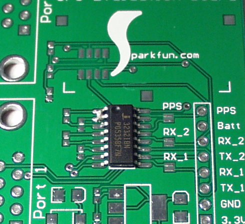
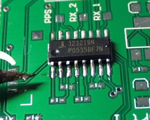
Nice and straight.
Once the package is aligned, remove the soldering iron from the pad holding the component still (applying a little downward pressure helps). If the pad solidifies and the package alignment is wonky, just re-heat the pad, re-align, hold still, and remove the iron. The initial heat-slide-align process takes a fraction of a second with a little practice. Do note: heating and reheating pads stresses them. It's totally normal for a beginner to 'lift' a pad on your first or second soldering project. 'Lifting' a pad is bad thing. It occurs because the exposed metal surface pulls away from the FR4 PCB material underneath (also called delaminating). Basically the pad and trace are toast, but you can always green wire from the pin to a local via or same-net pin. More on that later.
Okay, so once you've got the component soldered to the single pad and aligned, you can then solder to all the other pins. Start on the opposite side of the package away from your anchoring pad. If you start soldering from the anchor pin, you run the risk of reheating the pad and the component will slide around or stick to your iron tip. Tip: I usually like to have a small puddle of solder on the tip before I start soldering so that the heat transfers easily from the point of the tip to the pin/pad you are soldering to.
Once you've added solder to a few pins, you'll probably notice the solder can fill in between pins. This is ok. Solder that is connecting two (or more) pins together is called a jumper. Most of the time, this is bad and can cause problems. To remove solder between pins, you can use solder wick. Solder wick is composed of small copper strands braided together with some chemical additives that have been formulated and manufactured in such a way to attract the solder. Basically, you're playing with surface tension. With a little practice you can take a ball of solder on the end of your iron and run up and down an IC without ever creating a jumper - using only the surface tension of the solder ball and the incoming solder/flux to move things where they really should be.
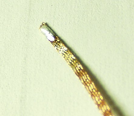
Since this is nearly impossible for, well, everyone, companies have created solder wick. We like size #2. We buy it in 50' rolls but we also use it like it's Kleenex so 25' should be sufficient for multiple small projects of your own. You can get solder wick here.
If you've never played with solder wick before, take the end of your iron and add some solder to the tip - get a good blob. Now take the tip and touch it to the solder wick. After a few seconds, the solder wick will heat up and the solder will migrate from the tip to the wick, spreading quickly - hence 'wicking' away the solder. Solder wick can't be re-used to my knowledge. Once the wick turns silver, you cut off the offending bit and throw it away. Well, try anyway. I usually cut off a 1" hardened piece that goes skittering off behind my desk or onto the carpet. Once you start using solder wick, you'll find bits hidden all around for years to come... But you've got to have it!
<
p align="center">
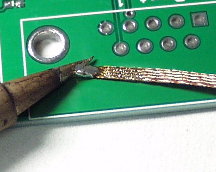
Now let's see what wick can do for us. If you're Mr. Fancy Pants and don't already have a jumper on your IC, make one - jumper two pins together. For the humans in the group that already have a few jumpers, take the end of wick in your bad hand. You'll want to hold 2-3 inches back from the operation because copper loves to transmit heat! I like to use clean, virgin wick so cut off anything that's already been used. Clean your iron tip and add just a smidgen of solder to the end of your tip (this will aid in heat transfer between the parts).
Place the wick length-wise over the two jumpered pins and push the wick down with the side of the iron-tip. Quick note: the very tip of the iron (such as the last 1/10th of the iron shown above) is not as useful as the length of the shiny area. Whenever possible, use the side of the tip rather than the point. You'll find that it is much easier to use and transmit heat with.
After a split second, the wick should come up to temperature and the solder on the iron and the solder in the jumper should wick into the copper braid! Now, keeping the iron touching the wick, move the wick away from the part. This entire process should take 1, maybe 2 seconds. Don't get crazy with the heating and re-heating or else you'll stress the pad and the IC. If you're just starting out, you'll probably pull the iron away first. Guess what happens? The wick solders itself to the pins. Just be cool. You've got a very strong metal to metal weld. If you go pulling on the wick you'll tear all sorts of things apart. Instead of pulling like a mad-man, add a bit of solder to your iron tip, apply the tip to the wick, and you'll see everything become molten again. Now remove the iron and wick together and you'll be ok!
But wait! When I wick away solder, won't that remove solder that connects the pin to the pad? Effectively removing the good connection? No actually. Back to the surface tension thing, solder wick is not strong enough to sneak solder out from under a pin and pad, only from solder that is floating without a pad to adhere to. This wicking process removes only solder jumpers or bad solder. Good solder connections are left in place.
Practice practice practice. It's not hard, it just gets easier with time.
Some fun tricks:
1) If you've got a jumper or part with solder hiding in a hard place to reach, add more solder! Adding solder to a jumper causes more flux to be added which helps heat flow. If you've got a bit of solder in a hard to reach spot, adding molten solder can be the microscopic hand that sneaks in, heats up the problem bit, and then you've got a much larger bit that can be wicked away.
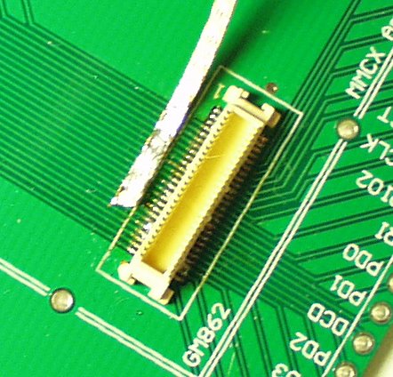
2) Smash and grab. If you've got a large number of pins to solder on a tight pitch SMD part (think 50-pin molex connector for the GM862), don't fret. Follow the same steps of adding a dome to the anchor pad, lining up and tacking the anchor pin.
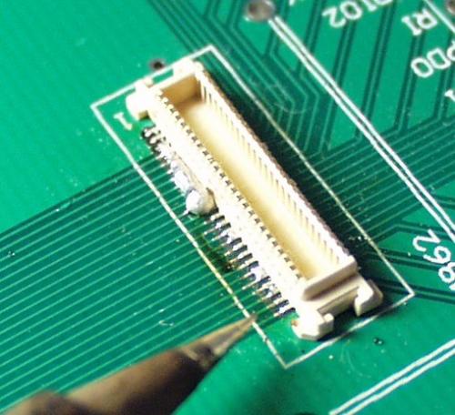
Now instead of trying to solder each pin, add solder and heat to groups of pins. Don't worry about jumpers, concentrate on getting proper solder on each pin/pad interface. If you don't properly heat each junction, cold joints and intermittent connections may occur later!
Once you've got the entire thing sufficiently jumpered, you go back with wick and carefully wick the extra solder away.
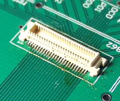
No microscope, no special tools required!
<
p align="center">
Here is a video demonstrating the use of solder wick and the 50 pin connector.
That's it! No magic tricks. Just a good iron, solder wick, and some practice. But what do you do when things get really screwed up?
Page 3 - Trying to reworking with an iron
Very good tutorial. I have been building pcbas since I was 12, but always through-hole. One question - what are the best temperatures for soldering various devices. I assume there are different temps since and temperature-adjustable iron is so important. Everytime I encounter an adjustable temp soldering iron I end up cranking the temp up to nearly max - I figure better to get the solder to flow quickly before the board has a chance to absorb a lot of heat and delaminate.
What tip size do you recommend? Great tutorial, thank you!
The video has no sound, every JPG is duplicated, but worst of all - you mention the absolute necessity of using a temp-controlled soldering station but neglect to mention what temp to set it at. But don't get me wrong - I still appreciate that you made this tutorial.
Could you add a how-to on hand soldering a micro usb SMD receptacle?
I have on my board a 100-pin connector with 0.5mm pitch. I see how the technique works above. In my case, I will order a Kapton stencil for the whole board, including the 0.5mm connector, and I will reflow it. I am worried that I will have trouble reflowing the connector. I followed the manufacturer's recommendations regarding the pcb layout and paste mask (you can see those on page 9: http://pewa.panasonic.com/assets/pcsd/catalog/p5k-catalog.pdf). However, the stencil manufacturer told me that it will be difficult to avoid bridging with this small pitch. Instead, he recommended to replace the paste mask (i.e. 100 cuts for each of the pads) with two thin lines perpendicular to the pads, one on each side of the connector. The idea is to reflow it and then rely on the surface tension to do its trick.
I am not sure what to follow. Has anybody any experience on reflowing 0.5mm connectors, and any opinion whether I should try the connector's manufacturer recommendation or the alternative suggested by the stencil manufacturer.
Thanks, Panos
Great tutorial but I'm seeing every picture twice
What those guys said.
I'm trying to view this tutorial, but none of the pictures are working.
Same here.
I also like flux, and I prefer the used portion of the solder wick.
Pin the part as above, then add flux to the pins and follow up with a loaded solder wick. The solder will flow out of the wick and into the pins at more or less the right amount, pull back the wick and inspect.
note - add electronics cleaner to your shopping list if you use flux.
Agreed. I always add some extra flux before removing the solder with the wick. It needs some extra cleaning after, but the solder joint is always perfect.
When you do decide that you really need the wet sponge, (you really do need it), the question becomes where to put it. One of the best receptacles for a soldering sponge is a cat food can. They are made out of aluminum, dirt cheap, and will contain the water just fine. The best approach is to get a packet of sponges from the dollar store. Look for something about 3"x5". Fold a couple of these sponges in half and insert them into the cat food can so the ends stick up. The ends will be about 3/8" higher than the edge of the can. The edges do a great job of wiping the tip of the soldering iron, much better than the flat area of the sponge. Fill the sponges with water from the tap and you are good to go.
Just a thought,
Dr. Spiff
I recomend the larger tuna fish cans, cut the center out of the sponge, that way the solder and stuff stay off of your desk. also more water = happy sponge.
So nice to see recommendations to put a bit of solder onto the tip to get good heat transfer. Tutorials I used to read never mentioned that. There used to be mortal fear of carrying solder to the work on the tip. If you're quick, and need to do so, you can, but normally you apply solder to the work (or work and tip together).
I've had good luck on closely-spaced solder connections by flooding the work with liquid flux; it's wasteful, but it prevents any oxidation, and solder bridges (that's what we called them) are less likely to happen, because surface tension stays healthy. Unless it's no-clean flux, you really ought to remove it; try alcohol.
Fwiw: I'm a retired tech; soldered surface-mount gold-plated ribbon-lead flatpack ICs (Westinghouse 930 DTL, $50 for a J-K flip-flop) around 1964 or so. These were before DIPs...