Member #435647
Member Since: May 6, 2013
Country: United States
-

I agree with others, this is an excellent set of articles on a subject I've been following for many years. Obviously a tough problem (although I think autonomous driving is one of the ultimate important tough problems in this space these days). Just wanted to mention that one company I first ran into doing this stuff back in the 90s was KVH. I was in on an eval of their driving system back then so they have been at it for a while. I remember it was pretty good "considering" but expensive then. Anyways, here's a link to some of their tech in case it helps: https://www.kvh.com/fog-and-inertial-systems/autonomous-navigation. The problem I have had myself with the reference point and triangulation systems is that, like GPS, they aren't consistent enough in terms of signal propagation. I'll be interested if anything new comes up in your search as you have clearly put in some good research
-
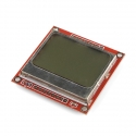
I just bought/received the "kit version" of this product (RTL-10773). The hookup and examples as shown here don't work with that product because the pinout for it is different. I don't know if at some point the breakout board the LCD is mounted on was respun with different hookups or if things were always wrong. Anyways, if you orient the display so the top is "up" (meaning the wider part of the metal bezel is up) then the pinout left to right on my card is: VCC - power, 2.7 to 3.3 volts GND SCE - Chip select (active low) RST - Reset (active low) D/C - Data (1) or Command (0) select SDIN- Serial data in from computer (SPI signal) SCLK- Serial clock line (0 to 4MHz) SLED- Powers 4 LED backlights but draws 80mA This DOES match the silkscreen pin labels on the back of my board. The wiring pictures shown above show the signals going to the following Arduino pins: pin 7 - SCLK, pin 6 - SDIN, pin 5 - D/C, pin 4 - RST, pin 3 - CSE
The Adafruit_PCD8544 library code which is the "library" referenced by the "SOFTWARE" section above is at:
github.com/adafruit/Adafruit-PCD8544-Nokia-5110-LCD-library That library has a constructor declared as: Adafruit_PCD8544(int8_t SCLK, int8_t DIN, int8_t DC, int8_t CS, int8_t RST); The pcdtest.pde example code in the library calls the constructor as: Adafruit_PCD8544 display = Adafruit_PCD8544(7, 6, 5, 4, 3); And unfortunately, that's broken. With the way the wiring connections are shown the call should be: Adafruit_PCD8544 display = Adafruit_PCD8544(7, 6, 5, 3, 4); Meaning the last two parameters are reversed. I hooked things up the way they are shown in the picture above and changed the example constructor call as shown and things worked just fine. But it would never have worked with my board as delivered.I just have to say that I'm new to this Arduino platform but have been writing embedded SW for decades. Even with my experience it took me a while to figure out how to set things up. I was worried that maybe the silkscreen pin labels on the board were wrong because the silkscreening on my board and which of the pins has a square pad vs all the other round ones didn't match the pictures either. Once I determined the pin labels were right it was an easy fix for me but someone less familiar with HW would probably have a lot of problems. I just hope that the people putting up these pages can double check them so that it will be easier for everyone to use these interesting products. I do realize a lot of good work goes into these products but any mistakes can make a user's job harder since my motto with SW is that "details matter - it's either perfectly right or it's broken".
No public wish lists :(