
MTaylor
Member Since: February 12, 2015
Country: United States
Tsunami looping firmware is released, and connectable by MIDI. And why not MIDI BLE? It's done with the nRF52832 this week.
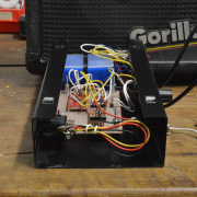
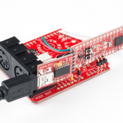
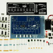
The serial controlled motor driver is stripped of its firmware and reprogrammed to function as an amplifier. Then it's surrounded with circuits that turn the whole shebang into a portable guitar amp.. but it won't win any awards.

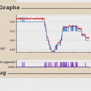
A look into how to decide when a knob has moved, so that your program can take an action.
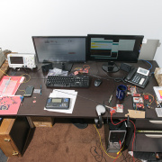

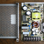
Here I've got 60 USB charger power supplies wired in parallel, just to see what happens.

This post explores how to use the power control features of the Battery Babysitter to make a product with the features we expect from portable embedded electronics.

The process of using open-source designs to get to a final product, featuring KiCad, PJRC, and Advanced Circuits.

This post highlights my method of creating the control system for our AVC battle arena.
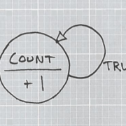
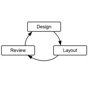
A look at implementing the Arduino blink.ino sketch as an explicit state machine. To further explore state machines, an alarm clock state diagram is drawn and implemented.
Qwiic 6DoF (LSM6DSO) Breakout Hookup Guide
May 20, 2021
A hookup guide for the Qwiic 6DoF (LSM6DSO), which features a 3-axis accelerometer, 3-axis gyroscope, temperature sensor, and FIFO buffer.
Raspberry Pi 4 Kit Hookup Guide
March 14, 2020
Guide for hooking up your Raspberry Pi 4 Model B basic, desktop, or hardware starter kit together.
MIDI BLE Tutorial
February 22, 2018
Developing a bidirectional MIDI-BLE link with the nRF52832 Breakout.
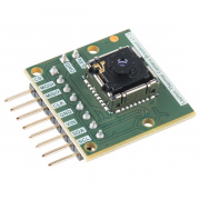
ESP32 Thing Motion Shield Hookup Guide
November 16, 2017
Getting started with the ESP32 Thing Motion Shield to detect movements using the on-board LSM9DS1 IMU and adding a GPS receiver. Data can be easily logged by adding an microSD card to the slot.
SparkFun 5V/1A LiPo Charger/Booster Hookup Guide
September 28, 2017
This tutorial shows you how to hook up and use the SparkFun 5V/1A LiPo Charger/Booster circuit.
CCS811 Air Quality Breakout Hookup Guide
April 27, 2017
This tutorial shows you how to get data from a CCS811 breakout board with the I2C interface.
Ardumoto Kit Hookup Guide
April 14, 2017
Learn how to assemble and drive DC motors using the v2.0 Ardumoto Shield.
TeensyView Hookup Guide
March 16, 2017
A guide to using the TeensyView OLED board to display text and graphics.
LIS3DH Hookup Guide
December 29, 2016
A guide to connecting the LIS3DH to a microcontroller and using the Arduino library.
Serial Controlled Motor Driver Hookup Guide
November 17, 2016
Hookup guide for the Serial Controlled Motor Driver
Proto Pedal Chassis Hookup Guide
September 22, 2016
Prepare the Proto Pedal Chassis by drilling holes for controls and painting it.
Beefcake Relay Control Hookup Guide
June 2, 2016
This is a guide for assembling and basic use of the Beefcake Relay Control board
Shapeoko Assembly Guide
April 21, 2016
A guide for attaching the Stepoko Add-on kit to a Shapeoko Mechanical kit.
Raspberry Pi 3 Starter Kit Hookup Guide
April 11, 2016
Guide for getting going with the Raspberry Pi 3 Model B and Raspberry Pi 3 Model B+ starter kit.
RedStick Hookup Guide
January 28, 2016
Learn about the SparkFun RedStick, a USB thumb drive-sized Arduino-compatible development platform.
Shapeoko Coaster Project
November 20, 2015
A step-by-step guide to cutting and engraving a coaster with the Shapeoko.
Raspberry gPIo
October 29, 2015
How to use either Python or C++ to drive the I/O lines on a Raspberry Pi.
SparkFun BME280 Breakout Hookup Guide
October 22, 2015
A guide for connecting the BME280 sensor to a microcontroller, and for using the SparkFun Arduino library.
SparkFun Line Follower Array Hookup Guide
October 15, 2015
Learn how to connect the RedBot Line-Following Sensor Bar to an Arduino-type microcontroller. Use the example sketches to read data from the bar, and try out a simple line-following algorithm.
LSM6DS3 Breakout Hookup Guide
August 13, 2015
A hookup guide for the LSM6DS3, which features a 3-axis accelerometer, 3-axis gyroscope, and FIFO buffer.
Getting Started with the Teensy
June 18, 2015
Basic intro to the Teensy line of products, with soldering and programming suggestions.
Teensy XBee Adapter Hookup Guide
June 18, 2015
Getting started with the Teensy 3.1 / Teensy 3.2 and XBee. Establishing a serial link.
-

FYI, the babysitter in the post uses high to disable rather than low to disable.
-
This is a pretty basic circuit, I've found that projects I make have a variety of needs so I have to get a bit creative depending on how I want the circuit to operate.
If you want the load to automatically be disconnected, use a small N type mosfet to pull the enable pin low with the gate connected to the USB in rail through a resistor.
If you require the load to stay active (and can tolerate a 0.5v drop) do the above but also put a pair of schottky diodes ORing the USB rail and the output rail to your load. That way the system will redirect power through the supply while pulling the booster offline. If there's too much of a gap in power, build an RC filter on the gate to delay the disconnection.
One project I built has a button wired to turn on the system (microcontroller) when held, and the microcontroller can then power itself off. So in this instance I simply shut the device down before charging. See this Enginursday.
Thanks for the bump
-
Chris is correct. Pulling the enable pin low disconnects the load from the battery -- I can't remember now but it draws something in the order of microamps during disable.
Alternately, I've found that minimal loads (<10mA) will still allow the battery cycle to complete. So if you can put your device to sleep or disable all of its peripherals, that's probably good enough.
-
Sounds great! Sorry if it was confusing.
As for that inductor, it shouldn't be chipped like that but it probably won't effect operation -- if the whole top comes off then maybe. It's part of the boost circuit anyway. If it fails you'll have poor (or no) current output capacity but the charger will still work.
Good luck with your project!
-
Good question. While the PAM has current limiting capacity through that resistor, the current limiting factor here is actually the inductor (as well as the source's current capacity). Let's say the thing is 100% efficient, 5W out = 5W in. If the output is delivering 1A at 5V, that's 5W power output. If the input is at 2.5V, and 5W is required going in, it needs 2A of input current. The winding of the inductor has resistance which can get in the way of the operation at high currents. See more including some graphs in the hookup guide connecting a load section. All boosters have this property-- the lower the input voltage, the higher the input current.
I designed this such that it can deliver 1A over the entire input voltage range of a LiPo. I actually took my measurements up to 1.3A on the output, but I'd rather provide something with a healthy margin that to call it a 1.3A booster.
-

That is fun! Thanks for posting. I'm curious, do you know when that was?
-
Hey Casey! I'm glad you enjoyed. I'm pretty sure it scales waaay up, to the limit of DC power supply and mosfet cost. It's a similar technique to one some robot builder I know is investigating.
-
That's kind of an interesting problem, you want to continue to boost but not charge, all while leaving the charger connected. There's no shutdown pin on the charger IC. I would investigate using a mosfet to switch the charger in and out of the circuit.
-
Thanks!
My main concern when designing this was to make sure the voltage was very noise-free on the output. I can't stand supplies that whine! With that in mind, output capacitance required is a based on the transient load characteristics, which I don't have any control over. a single 22uF may have been fine, but two is better here! And yes, I was considering that less specific components on the board means less work to build, even if it's only a single reel in a machine.
The diodes allow the boards to be used in series -- see the hookup guide for more info. If one goes dead in a chain, the current will be passed by.
-
The booster is regulating to 0.6V on the feedback pin (FB). Adjust the voltage divider made by R1 and R4 using 0.6 and your desired output voltage as constraints, and it should be OK. I solved R4=600k (with R1=100k) for 4.2V output... maybe there's something else going on here.
The inductor value is not critical to regulation voltage.
Also, R4 is stuffed with 750K from the factory so I'm not sure what's up. I'll let you know if I discover anything.
Keep in mind you can't buck down from a larger battery voltage! The PAM2401 only boosts.


