3D Models of SparkFun Parts!
Find out how and why we're modeling our products in 3D... and how you can help!

Computer drafting technology has come a long way in just a short time. That makes sense, I suppose, because computers haven't been around for very long. Even the mathematics to describe curves in a computable way is fairly young. Only a few decades ago you had to use CAD (Computer Aided Design) software without a mouse, typing every coordinate and describing every curve. By the time I started using CAD, it was a click-and-drag sort of operation. Some math was still involved but getting an idea from your head to the page was a lot more intuitive. You were still limited to flat cross-sections, though, if you wanted to describe a 3D surface. The first time I saw 3D CAD software, it blew my mind.
Now? Now you can go download any number of free 3D CAD programs and start virtually prototyping. My personal favorite is SketchUp, which was developed at Google and recently acquired by Trimble. I don't know what you do on a long airplane ride, but I like to get out my laptop and fire up SketchUp. It satisfies my urge to create while I'm stuck in a decidedly "screwdriver free" environment. Modeling something in 3D has become an integral part of the design process for me. Often it helps me figure out whether or not to pursue a project in real life, sometimes it's satisfying enough just to model something.
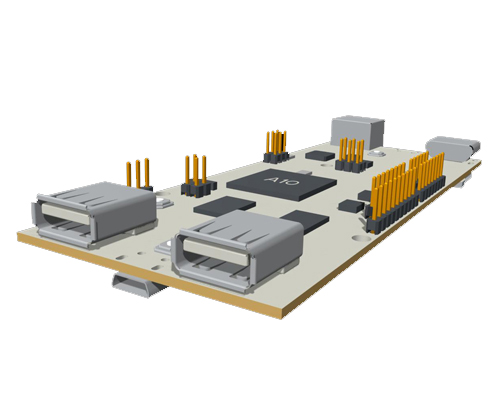
Paul's awesome pcDuino model... wait a second... is that pcDuino about to engage warp drive?
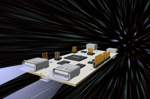
I knew it!
One use that I've found for it is in modeling an enclosure for my electronics projects. If I can make models of the different boards and sensors, I can experiment with different layouts without ever cutting holes in a real enclosure. And with the advent of desktop 3D printing, you can even design a custom enclosure specific to your project and have it in your hands within a few hours!
It turns out that more and more of you are either doing this or are interested in doing it, so we decided to help out by providing 3D models for some of our products that we think need them most. Right now, we're a small team: Paul (Our Minister of Machinery), Nic (Graphic+Motion Design Extraordinaire) and myself. Nate (our fearless leader) sprung this idea on us a few weeks ago and since then we've been working on ways to approach it. We have a lot of questions: What file types are most universal? What software are people using? Are people using these for 3D printing or virtual prototyping? Can we get some help?
So we figured we'd just ask.
Of course, we need structured feedback, so here's the plan: We've set up a GitHub repository for 3D models. Check out the guidelines below and if you think you've got a model that we need then clone the repo, add it in and send us a pull request! As we go forward, every product that has a 3D model will get a special icon (like the OSHW or RoHS icons) as well as a link to the model.
The things that need models the most are the items that are likely to be mounted in some way: switches, breakout boards, LEDs, Liquid Crystal Displays, anything that pokes out of an enclosure. Pay special attention to the dimensions of mounting holes, headers and connectors (get out your calipers!) If you submit a model to the GitHub repository and we pull it in, we'll give you a shout-out in the readme file so people know you contributed!
The basic guidelines for submission are:
- STL or SKP File Type
- 1000x Scaling (EDIT: We've heard some convincing testimony that 1000x is the de facto standard)
- Enough identifying text or logos to convey the orientation
Also, before you start working on a new model, check the "bare components" folder in the repo. We're putting together some basic component models for generic ICs, capacitors, etc. which will help all of our models look uniform and also save us all a lot of time. If you end up having to model a component, send that to us too!
There are already a lot of you making 3D models of our boards (we've seen your work) and hopefully we can all help each other do less redundant work by pulling our resources into a shared repository. So what do you say, give us a hand?
In the comments, let us know if you're using a 3D modeling program to prototype and, if so, which one? Oh yeah, and if you've got a 3D printer we'd love to see your projects that incorporate 3D printed parts made from our stuff!
Update: It looks like a lot of you (and some of us) have vouched for 1000x as the new sizing standard! We'll re-scale the models that we've already made to keep the repository consistent. So if you want to submit a model to us now, make it 1000x life-size. We won't change this again, promise!


EagleUp? (http://eagleup.wordpress.com/)
Love Eagle + Eagleup + Sketchup an invaluable tool for checking a board fits in a box or just reviewing it.
I wish people were as excited about spice circuit analysis as they are about 3D modeling programs. My last project which admittedly needs a good writeup, was designed entirely in LTSpice. No prototypes. If that didn't sink in: NO PROTOTYPES. Just design, model, and make the final circuit board in one shot. Worked perfectly the first time.
This sounds awesome!
I would suggest that whatever format you settle on as the default, you also collect and make available files in the native format for the CAD program that they were created in. For example, SolidWorks or Rhino or whatever in addition to the STL. That way, others who have the same software will be able to update or adapt the model.
See if you can open either the step or igs file and let us know!
Like Nick said, I am using Cinema4D for the models i create. Its not a "CAD" program persé. Its more for animation. Is there any interest in my .C4D files? My guess is that there are little to no people interested in this file type, but I might be totally wrong. Is there any interest in having these posted as well?
I use C4D for my CAD work as well. I will usually just export the models as OBJ or STL files. I for one would certainly like straight C4D files, if possible.
Awesome! i was out of the office on friday when we have our 3d meetings, but im guessing we will be putting all the original files up too. :)
I like that idea a lot.
I've been working on some Ruby gems for procedurally generating geometry and then exporting it to all of the various file formats. It's like OpenSCAD or ImplicitCAD, but using a Ruby DSL instead of a custom language. The idea is to be able to write the code once and then generate whatever file formats end up being needed so that you're not locked into one format, or vendor. It also makes it easier to manage the files in a version control system. So far, I can only export to SketchUp and DXF. I'm working on STEP next.
If anyone wants to give it a try, let me know and I can help you get started.
Edit: Here's the toplevel repository on GitHub: https://github.com/bfoz/engineering I know, I know, the documentation is terrible and I have a lot left to do. I'm happy to answer questions and help anyone give it a go.
I second http://www.3dcontentcentral.com.
If y'all can get added as a "supplier" then they'll host all of your files in an easy-to-download and easy-to-preview structure. I use them religiously when dealing with 80/20 and they're my go-to source for stock 3D components.
I'll definitely help you model stuff, on a grand scale. Seriously. Hit me up.
Great idea! I'm using SolidWorks but I think that step files would be versatile enough to port between different platforms.
See if you can open either the step or igs file and let us know!
Paul Smith, after seeing this comment on every other post, I figured I would go through the simple task of checking. Both files refuse to open. The step file says: "Incomplete file" and the igs file says "Unable to read IGES file. File was truncated or contains invalid data."
I hope this makes you feel better, that someone finally responded. Also, this was performed on: SolidWorks Premium 2011, because you can't always get the newest release when strapped for money.
-Steve from NSL
Try this link
I have no problem opening the .stp file in SolidWorks 2013. The components are all there, neatly arranged in an assembly. Only the nice color is gone and the whole board is grey.. ;) The .igs file is only 22 bytes, I did something wrong trying to download it from github ,let me try that again.
The .stp file does not have color encoded into it, but it could and Creo supports the capability. When there are no colors in the STEP file, some systems like IDA-STEP Viewer assign different colors to different parts and geometry. Other systems leave it grey, like FreeCAD and apparently Solidworks.
Try this link, there seems to be an issue with downloading an individual file that is large. This will download the entire repo.
Github often corrupts files if you don't download them using the "download as zip" feature. Eagle libraries from the sparkfun repository don't load in eagle if you downloaded them individually. It's weird. No errors given, they just don't work. Haven't looked at a diff yet.
Ok, thanks. The IGES file looks great, but SolidWorks crashed after moving around some components.. The .stl model loads really fast, and seems stable. The holes are noticeable polygons and the reset button has a diamond shape, but for making a housing this may be good enough. Is there a way to increase the resolution?
From my experience, in industry, the .stp are most popular (CNC machining, 3D models) because they are versatile and accurate. But from this small test, it seems now that .stl is more versatile, albeit less accurate. I think I could live with that. But.. wouldn't it be nice to have different formats?
Thanks for the feedback, I'll try and see what's up.
I prefer EagleUP for quick model generation, and it has a decent library to start. The author is responsive to feedback, so I'm surprised it hasn't captured more interest in two years: http://eagleup.wordpress.com/warehouse/
Models need to be scaled to 1000x for EagleUP. What's Sparkfun using that requires 100x? It would be massively helpful if models were interchangeable between scripts/software.
EagleUp is great, we're going to use it a lot for the boards that we design in house.
We chose 100x somewhat arbitrarily. The reason EagleUp uses 1000x scaling is because of SketchUp's reluctance to work at small scale (there's a lower limit to feature size, which I find odd but it was developed for modeling buildings so... there you go) But Paul, our mechanical engineer, uses Creo to generate his models and claims that it's a pain to scale things down when we give them to him at 100 or 1000x. We figured it was worthwhile to accommodate SketchUp users but decided to compromise and only scale to 100x.
Our models don't have to be precise down to the legs on the ICs, so even at 100x there shouldn't be any features that are too small for SketchUp. But when importing the model to another program like Creo, hopefully 100x causes less of an ordeal than 1000x.
We're open to discussion on this point, though, what does everybody think makes the most sense?
I'd push for 1000x. That way, your 3d model's dimensions in meters are the same as your real object's dimensions in mm, no decimal scooting required.
Anyone else have thoughts on this? Non-Sketch-Up users? Is a larger model harder to deal with or are you just as happy with 1000x as you would be with 100x?
If we're gonna change it, we should probably do it yesterday before people start sending us pull requests, lol
So as a professional CAD modeller I can say I've never heard of doing this, but I understand a lot of people use Sketchup which needs this. I've only tried sketchup once and never looked back - solidworks is my tool of choice, and it would actually be pretty bad in solidworks to do this, since it doesn't use generic "Units" but actually uses mm, inch, etc units internally (unless you're exporting STL).
Also, for file formats STL is horrible. Can we encourage IGES or STEP if possible? Does sketchup support that?
+1 for 1000x so that we can use the models in EagleUp as well.
1000x it is! Better to change now than later!
I've used Creo for 5 years now, both professionally for a large semi truck manufacturer and for education/hobby. We've always used 1 to 1. There was never any confusion and mistakes were rare when generating large 12GB rendered models.
I hear ya on that one!
Right, obviously 1:1 would be ideal but SketchUp, which is a popular software for this kind of thing, won't work at scales that small. There is a lower limit to feature size that precludes modeling things like SMT components 1:1
+1 for SketchUp. I've been using it since 2006 to aid in prototyping projects.
Just want to share what I discovered: An amazingly easy way to get 3D STEP (and more) from my EAGLE brd file. And: It's free !! http://www.pcb-pool.com/ppus/order_productconfiguration_js.html (No - you do not have to order anything from them ;-)) Enjoy
I know this is a fairly old post but I was wondering if 3D models of parts are something that is still desired? I'd like to improve my SketchUp skills and do something useful/help out in the process.
Absolutely! Check the repo. That's going to show you what parts we already have versions of and which ones are blatantly missing still. If you want to contribute, we'd love the help!
Can anyone recommend a good Github tutorial? I'm very into this product model idea, and I can make the files in skp, or step, or dwg, or whatever, but I have no idea how to use Github, even after reading the help. Perhaps there is another way one could submit models, like a Thingaverse collection? I also think it would be sweet if we could add confirmed printed enclosures for products.
Git Reference and the Git book helped me out a lot. They are aimed more at git in general, but understanding that helps with using GitHub.
You want models? I've got 250 students ready and waiting to model stuff in 3D! Right next door to you in fact, CU Boulder Mechanical Engineering. However, I strongly suggest that files be made available in STP or IGS. STL is not useful because it seriously degrades the quality and also is not importable into SolidWorks. I don't know much about the SketchUp files but I think that the professional world is more likely to be interested if you have STEP or IGS.
SketchUp was NOT developed by Google! It was developed by @Last software, of BOULDER COLORADO! For shame, Sparkfun! Not only are you simply wrong on the facts, but you have failed to give your neighbors credit where it is due! Nick, correct this post post-haste! Further, invite them over for a beer! They deserve it! XD
This has been already mentioned in the comments, and like Brennen I used to walk by their offices quite often. In Nick's defense he's a relatively recent arrival to Boulder, but he's making a big splash here; stay tuned for his latest adventures.
Following funkathustra's three points, I need to add another:
Many vendors will have STEP files available for download or by request (I have yet to encounter one that didn't provide me a STEP file for the component I was interested in.) I use FreeCAD to open that Step file and export a mesh. From there I open the mesh in MeshLab and export it as a COLLADA .dae file which I can then import into SketchUp. I'll save that file out into my SketchUp parts library so the next time I use it in EagleCAD and export it through EagleUp, it will pick up that component. Yes it's a process to get that component in SketchUp format but it sure beats having to draw it from scratch.
Three things to note:
1) No one uses anything other than STEP / IGES for 3D EDA design. So, if you really want to set up a component repository, I'd suggest you make sure those formats are available.
2) I guess I'm trying to figure out why you're setting up a repository in the first place? Everyone in the industry I know uses 3D Content Central. It's already established, has tens of thousands of parts, is free, and allows user uploads. Why reinvent the wheel?
3) The fact that you have 50 posts discussing which arbitrary scaling to apply to components or which file formats to support (what the heck is an SKP file?) is a good sign that you're not doing it right.
+1 on 3D content central
+1 on your +1
EDIT: SCALE is the most important thing to sort out.
Dickering of over the "export" format is going to create a library of mess. Each model should have the source program's native file format, a bunch of exports of different filetypes and any textures in a non-proprietary format. A REAME is also a good requirement: It could have a boilerplate that could be used to generate a library "listing". The README should list the version of the source program. The README should list the scale (eg. 1" X1000)
EDIT: I have converted a LOT of models (literally 1000's) from all kinds of sources. You do not want to clean a model in some crappy format. Getting the source files is your best bet to having something useable. As a couple of people have pointed out, most formats have versions that had compatibility issues, which is why I suggest having a number of options. Compounding the format choice is the exporter implementation in any given source package. It all adds up to more is better in the case of exported models.
Tried the step and igs files in AutoCAD 2013. Both imported, but the igs file had some big tubes floating around by the hdmi port.
STEP was designed to replace IGES. IGES has not been updated since 1996, and IGES implementations have incompatibilities, as you discovered.
I did not know that. Thanks!
I have just upgraded to SolidWorks 2013, but the step and igs files keep crashing. Anyone else having this problem? I tried saving back to SolidWorks native, but it only delayed the crash.
The step has not crashed yet.
step and IGS working fine in solidworks 2012. Sorry can't help much on the '13
For anyone attempting to open the .igs file for the pcDuino, Try this link. There seems to be an issue with downloading an individual file that is large.
I tried opening your example STEP file in both Altium 12 and 13, and it refused to import then threw up a bunch of errors...
Checked the STEP file for pcDuino with a validator, the free IDA-STEP Viewer Basic, which was able to view the geometry and get the assembly information. FreeCAD loads it much faster because it does not validate the file to the STEP schema, and was able to view the geometry. FreeCAD does not have assembly capability yet, but it can convert the STEP file to STL. Don't know what the issue Altium has with the STEP file.
You can find a listing of vendor's STEP translator coverage here http://www.cax-if.org/vendor_info.php Many other mechanical CAD packages like Solidworks, Solidedge, Autodesk Inventor, Spaceclaim, Rhino, etc. can handle STEP files. However, they or their STEP technology provider may not keep up with advances in STEP if they are not a CAX-IF participant, so I recommend validating their STEP exports. Can you post an Altium export to a STEP file?
The STEP models from McMaster-Carr will import into Altium with out a problem, if that information is any help.
Adding my two cents. I have been doing 3D PCB design for 5 years now in Altium, which does 3D board design and mechanical constraints really well. All parts come in as .STEP files which most parts vendors now supply.
I vote STEP files please over .stl Leave the STL files for the Makerbots and Repraps.
Sketchup's format is tessellated, so it does not natively support NURBS/BREP for exact geometry and topology like mechanical CAD tools. Sketchup also does not support the ASME or ISO standards for Product Manufacturing Information (PMI) annotations. Sketchup was intended for architectural modeling, but it is suitable for some mechanical concept modeling applications. The free Sketchup version is convenient, but you can get NURBS/BREP and tessellated file format support with FreeCAD.
I confess that I am slightly unclear what this has to do with the comment it is in response to.
Good point, my bad. Probably should have been posted somewhere else since the comment regards what Sketchup is capable of, and why. FYI, I talked to the Sketchup folks about a year ago in terms of adding PMI features for mechanical CAD, but they were more interested in adding features for architects. Now that Trimble Buildings bought Sketchup and Vico (also from Boulder), they will likely continue to focus on the Architecture, Engineering and Construction industry where they make money. The free Sketchup can be used for things other than it was intended, like mechanical CAD concept modeling, generating tessellations for additive manufacturing, etc. But if you need precise geometry, mechanical assembly data management, and Geometric Dimensioning & Tolerancing (a subset of PMI), you need mechanical CAD tools. FreeCAD can do the first, and is working on the second. Commercial mechanical CAD tools like Solidworks and Creo mentioned in this discussion can do PMI to varying degrees. Sketchup (and Blender), cannot and probably will not ever be able to do any of them.
Freakin' sweet! I've just tutorialed my way through Sketchup and discovered Eagleup. This will be incredibly valuable for getting my projects to another level of professional! Thank you, thank you, thank you!
Google+ Post and Comments https://plus.google.com/u/0/106084846822083498483/posts/Cy8CM647AMY
Would a V1 beaglebone be useful in the repo, I did an altoids tin and a tin that came with the v1 beaglebone a while back. The adafruit cape for beaglebone as well. source
Submit it and I'll check it out!
I'd recommend to utilize some soft of cad data management system. The pitfall with many of the free to share locations today, is conformance to managed metadata, bom structures and parent child relationships.
If you could deploy a CDM on the back end of your site that maintained this data, someone could selectively download the entire assembly, simplified reps, drawings, etc of an upper level assembly in a single click (ex the pcDuino). It makes finding common library parts significantly less painful and much more efficient. Further, all future designs use the same base component parts as reference designs/ sub assemblies.
I haven't told you guys that you're awesome lately...
YOU'RE $#!$@#)@%@$$()@#(@!)$# AWESOME!
Any suggestions on good tutorials for SU? I've been wanting to learn for a long time but just haven't gotten around to it. Now that I have my own printer, I need to learn to use some sort of CAD software. I know there are some basic ones built into the program. Is that sufficient? I do know a little bit of OpenSCAD and that's fine for some things but difficult for some others so I wanted to pick up SU to know both and take advantage of each one.
+1 for real CAD formats... In case you did not See it on hackaday you should have a look at eagle2freecad https://github.com/ch-aurich/Eagle2FreeCad
See if you can open either the step or igs file and let us know!
I just wanted to echo the sentiment of using FreeCAD. Sketchup is nice, but is definately not intended for this sort of thing, it is also proprietary software whereas FreeCAD is FOSS.
FreeCAD has the potential to become the defacto OSHW standard, I would love to see that happen. /$0.02
Thanks! I'll check it out.
For MCAD programs, STEP/STP and IGES (though STEP/STP is becoming more popular) are the standard interchange file types. STL is used for 3D printing, but is not a very clean geometry when importing everything into a standard MCAD program. All the surfaces are represented by triangles.
Yeah, we explored IGES but had trouble importing and exporting clean models between our applications (SketchUp, Creo and Cinema4D) We found that STLs did maintain their grouping, though, which we thought was important. Also, SketchUp (and I suspect other modeling programs as well) has a tool for smoothing coplanar faces which I use to convert STLs into cleaner and more manageable files when I import them.
You can export a DXF file of the board from Eagle cad and import it into a Solid Modeling program. This will be a lot more accurate then a caliper =)
We already do that! And as far as accuracy goes, there are always inaccuracies introduced by the machine routing the board, the pick and place machine dropping the parts, and cutting apart a PCB panel. So whether you use the eagle file or measure by hand, the end result is going to be the same - pretty darn close. No two boards are truly identical.
Thats why they created tolerances =)
Seconded on the tolerances; please include tolerances in the completed drawings; even "hand sanded" should have specified tolerances.
+1 for something Solid-works friendly. .SLT files are not very Solidworks or Pro-E friendly at all. .STL is great for a 3D printer but most CAD/CAM software will not accept it as a format and allow you to do much with it. If i want to cnc an enclosure around the board an .STL is no good either as most CAM companies don't support it. On a side note Solidworks has an educatioal version you get get for like $150 bucks.
Try this link, there seems to be an issue with downloading an individual file that is large. This will download the entire repo.
IGES and STEP are both cool with Solidworks 2012. I can open either one fine and work with them for machining as well.
Great! Thanks for the feedback!
See if you can open either the step or igs file and let us know!
I use Creo (Pro Engineer) and have no problems with stl files at all. Although I do prefer igs over everything else. It maintains colors and individually assembled parts.
Personally, I use Soliworks or 3dsmax.
See if you can open either the step or igs file and let us know!
I tried to open some of the models and the .skp files don't open with SketchUp 8.
Can there be links to the 3D models of the part on the part page?
There will be, we're working on it!
You say that models should be exported with '100x' scaling, but you don't specify units. I think it would be more useful to specify units (m, cm, inches), since they're directly measurable.
I'm not sure I understand. 100x tells me something about the model's size relative to the measurable size of the object. Units should be interchangeable and describe the size of the object. Am I missing something?
EDIT: In other words, I personally don't care what units the model is in because I can import it in metric or imperial. What I care about is that if the original part is 1 foot across, it's now 100 foot across (or if it was .305m it's now 30.5m)
As far as I'm aware, STL doesn't include units, so any exported models have to specify both the scaling and units. Specifying units and scaling is redundant, particularly if you're working in metric, because units of meters with 100x scaling is equivalent to specifying units of centimeters.
When using Solidworks, I prefer to use actual units rather than 100x units. This makes it easier to measure and verify things in my model, esp since solidworks understands and models units, not just values.
I suggest adding a file naming convention so that it's easy to associate parts with their solid models. For those of us making models in other formats, I think it makes sense to include both the source file and the exported STL in the repository.
There is a naming format, I can't believe I didn't include it in the readme. I'll go add that now. Thanks for reminding me. As for the source files do you mean that if you generate a DWG or an IGS, you think that it should be included with the STL? Interesting, why do you say that?
It could be helpful, as more information is typically available in native format.
I talked to our 3D crew and it sounds like source files are a good idea. It might allow people to fix models that they're not satisfied with and re-export them. I'll put a note in the readme!
My thoughts exactly. I do all of my modeling in Solidworks, so I've included my source Solidworks files in my pull requests. There's more information available in the solidworks files, and including them will make it easier to improve models that are already in the repository.
+2 for Sketchup. Been using since 2008 and no complaints about its functionality and versatility. Perfect for modelling. There are also some tips found on the sketchup blog / newsletters on what to do and add-ons are available to get the right output for 3D printers, although getting this right is a little trickier.
Ha! I helped. Very glad this is happening. Thanks SFE!
I use SolidWorks, but that doesn't meet your needs/scope. I have it at work and use it regularly. One free source for 3D files is http://www.3dcontentcentral.com/default.aspx. They do have a few Arduino boards as well as comon components. I applaud this effort and while I'm not familiar with the software or stl or skp files, I am now going to look into it. Thanks!
See if you can open either the step or igs file and let us know!
Why do you feel SolidWorks does not meet our needs/scope? I'm doing all of my drawings in Creo.
I think it is a very powerful tool. I see the cost as a limiting factor for many interested here. I would imagine whatever you end up using must function for SolidWorks users, but be accessible to those without a college/company/deep pockets to pay for the software... more open sourcey.?!
Ah gotcha. We are aiming to post universal filetypes. For right now, .stl is what we are going with. If you create something in SolidWorks and export is as an stl, anyone can open it up in other CAD programs, like sketchup.
Just for clarity, step files is NOT the SolidWorks native format. I am suggesting this because it is so interchangeable between different platforms. But I am not familiar with Sketchup or popular 3D printing applications. Anyone experience with converting .stl?
Correct, sldprt is a native SolidWorks filetype, not step. stl files are a very common file type for lots of 3D printers. I can import/export stl from Creo and the same can be said for Sketchup. Github also has a built in stl viewer. It's a very universal format.
Just for the record STL files do not preserve native geometry. STL files break a part down into small triangles based on how fine the resolution was set when the STL file was created. One of the issues with STL is that if the part is very small, has lots of compound surfaces, etc, some of that detail can be lost.
STEP files preserve the original CAD geometry as surfaces and solids with no native resolution.
STEP or IGS are considered the preferred formats for exchanging CAD data, and as a Mech-E I prefer them, but anything is better than nothing.
See if you can open either the step or igs file and let us know!
That was my concern with stl too. Being that you can change these settings upon exporting, there is no 'one setting' that fits everyone's needs. If there was a way to make igs work for every program, I would love to use it.