
I've always been curious about how things work. As a child I took a lot of things apart - clocks, toasters, even a discarded IBM Selectric typewriter (which turned out to be full of solenoids!). As I got older, I reached the point that I didn't just want to see what was inside, but I also wanted to put them back together, perhaps even improving them in the process.
So I learned to keep track of the screws as they came out (a muffin tin is really useful to keep them in order), and to use the right tools on the fasteners, so I didn't strip or destroy them in the process. This coincided with the rise of the internet, which is extremely useful for tinkerers/hackers/makers. We can connect with other people with similar interests to compare experiences, trade techniques and share our discoveries. It's also a great research tool - whereas before I might have gone to the library and looked up a cursory article in an Encyclopedia, today I can find a much more detailed article on Wikipedia, watch a lecture on Youtube, or simply be inspired by all of the projects other people are working on.
From that basis, I'd like to present an ongoing project of mine.
Background
It seems like cameras are everywhere now. On any given day, I've got two or three devices in my pocket that include cameras among their many features. They shoot acceptable photos and video, and they're always with me. But I'd heard some people grumble about the quality of the optics, and even seen people modifying them to accept different lenses. I was intrigued - this was an area I knew almost nothing about, but was eager to learn more.
The little cameras are usually set up so that nearly everything in the image is in focus. While this is convenient for a point-and-shoot pocket camera (just pull it out and snap pictures - no need to focus or set the exposure), it's not always desirable. When everything in the frame is in focus, it can be hard to draw the user's eye to the proper details. If you can selectively focus on a specific region, the viewer's attention will be drawn to that.
When I first became aware of this, I noticed that it's extremely prevalent in recent movies. Filmmakers keep the actors in focus, but the background blurry. They may even "rack focus" in a shot, shifting the perspective in the scene. In optical terms, the region that is in focus is known as the "depth-of-field." Images with everything in focus are said to have a large or deep depth of field, where images with more selective focus are said to have shallow depth of field.
Doing a little research yielded a number of online sources describing the equations that govern depth-of-field. It actually comes down to a few factors:
- The focal length of the lens - Longer lenses exhibit shallower focus on near objects.
- The relative size of the aperture - Wider apertures will also have shallower focus.
- The distance to the object - The field gets deeper as objects get farther from the lens. Eventually, the far limit of the depth of field essentially extends to infinity.
- The size of a dot that is considered "sharp" - the size of the chemical grains in analog film, or the size of a pixel on a digital sensor
Therefore, a longer focal length with a wider aperture, pointed at a nearer object, will exhibit a shallower field.
First Try
I'd seen several projects where people grafted large lenses onto pocket cameras to obtain selective focus.
It looked like something I could try at home, so I picked up a little Kodak pocket camera and a couple of old television camera lenses from Ebay. My approach was going to be to remove the stock lens from the camera and replace it with one of the television lenses so the camera's image sensor was located in the image plane of the lens - a lens transplant, as it were.
The camera came apart easily enough. A few tiny screws to get the case apart, and a few more to get the PCB loose. The factory lens was also easy to remove - it may have just been held in with doublesided tape.
The lens I got was a 25mm f/1.4 manual focus C-mount television camera lens. The aperture of f/1.4 is pretty wide - I was hoping it would work for the shallow field effect.
C-mount lenses are common in many disciplines - television cameras, security cameras and some motion picture cameras all use them. C-mount lenses fit a 1-inch 40 TPI threaded hole, and the image is formed 17.52mm behind the mounting surface.
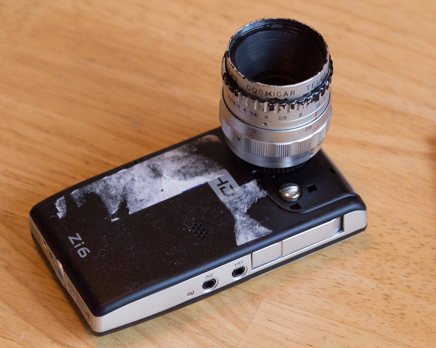
I carefully drilled a 1-inch hole in the case, then reassembled the camera and measured the distance from the surface to the sensor - it was about 12mm, not the needed 17.52mm. Thankfully, there are C-mount extension tubes, which come in 5mm increments. I screwed in one of those, as seen here.
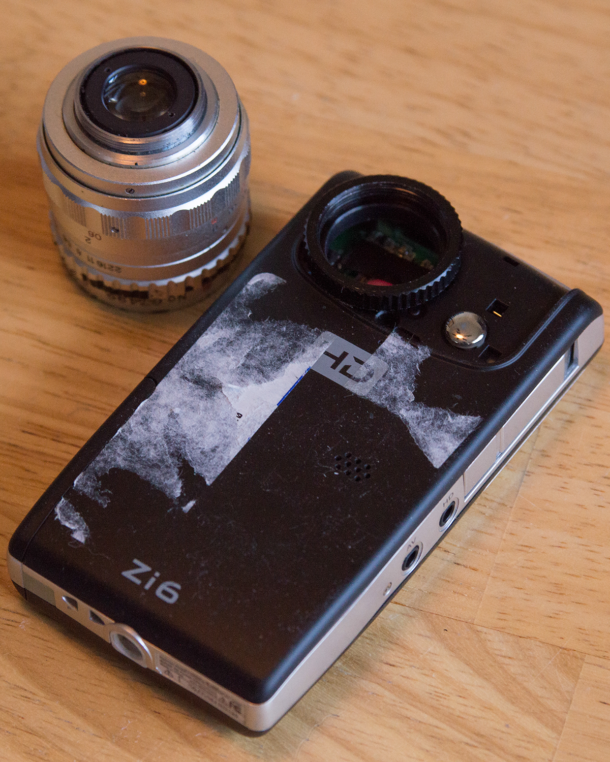
Then I screwed the lens into that.
The initial results were shocking and disappointing - everything came out overly red.
It turns out that there was an infrared blocking filter in the original lens assembly - a tiny piece of irridescent pinkish-blue glass between the lens and the sensor. I was able to pull it out of the lens assembly, and tape it on top of the imager.

It built on a lesson learned from previous tinkering - always save the parts you're removing!
So did it work? I'd say it was a mixed success. I was indeed able to obtain a shallow focus, as Shorty and Blockhead below can attest to.
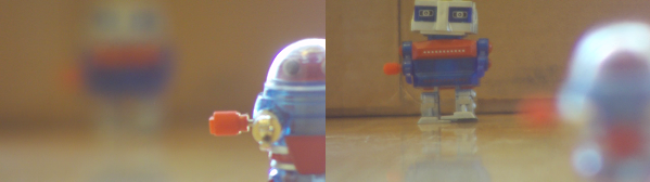
Near/Far Shallow Focus
The imagery was somewhat successful, but there are several aspects of this hybrid that make it rather hard to use.
- When focusing manually, you need to be able to see the image clearly enough to know what was in focus. The screen resolution is low enough that it is very hard to tell what's in focus.
- The sensor in the camera is tiny. It's only using a small portion of the image coming from the lens. The result is that a 25mm lens acts like a telephoto.
- With the telephoto-like behavior, the stability of the camera becomes important - it needs to be held still, because it will show even the tiniest movements. With a glass and metal lens on the front of a flimsy plastic box, it was very front-heavy. The plastic tripod mount also turned out to be somewhat flexible.
- The camera was designed to provide everything the user needs automatically. The factory focus was deep and fixed, and the camera managed its own exposure levels. In adding the manual lens, the camera sometimes worked against the operator's lens adjustments. For instance, if I tried to fade to black by closing the iris, the camera would compensate by boosting the sensor data, resulting in a really noisy, pixelated black.
So the Kodak got put aside for a while, and I worked with other, more fully featured cameras.
Since then, it seems like lens swapping on pocket cameras has become more commonplace. I see several commercial offerings that allow lens interchangeability, particularly for the GoPro cameras.
Second Try, Part A
The first hacked camera sat in a box until I was inspired by my colleague Joel in his Enginursday post three weeks ago, coupled with a couple of his older posts, about using the Raspberry Pi camera.
A different apporach to adding external lenses to a small camera is to build a camera obscura using an SLR lens. Rather than putting the image sensor in the focal plane of the lens, it places a translucent screen there. The lens focuses the image on the screen, and the digital camera focuses on the screen. This is known as a Depth-Of-Field (or DOF) adapter. I hadn't yet built one because the translucent screen seemed like it would be hard to locate and mount.
In Joel's Lunchbox Laser Show, he was using an Actobotics wheel as a spinning diffractor. The lightbulb over my head came on - maybe I could use one as a screen to build a depth of field adapter. And I could use a more open, hack-friendly base system using the Raspberry Pi and Pi Camera.
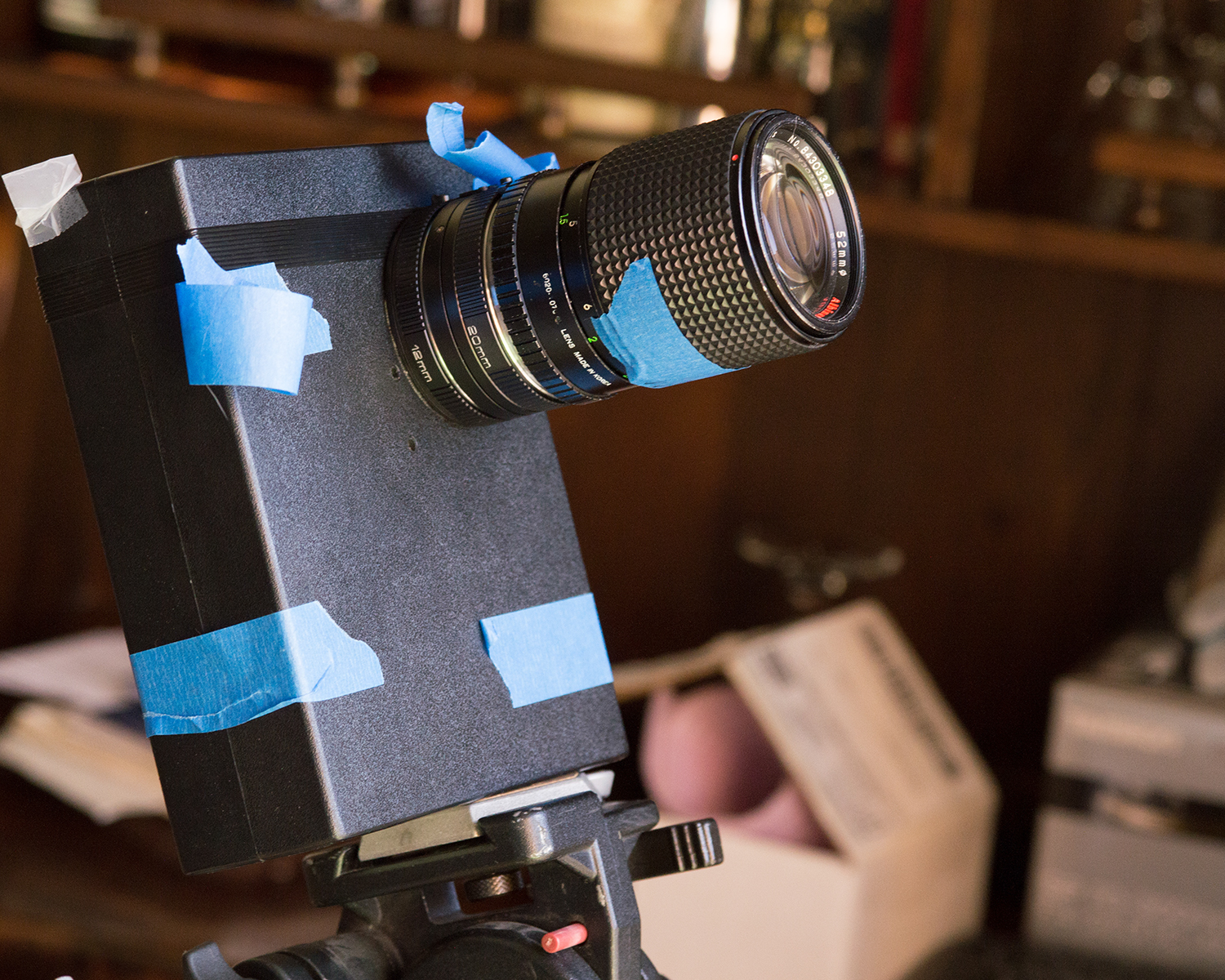
My local camera shop has a bin of old, cheap lenses for $7 each. I pulled out a moderately fast lens - a 135mm f/2.8, with the old Minolta MD mount, bearing the Albinar ADG brand. I also picked up a set of Minolta macro extension tubes to use as the lens mount.
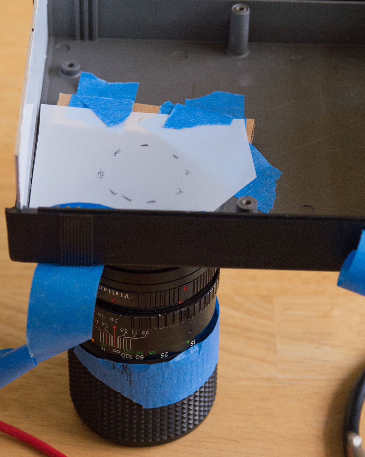
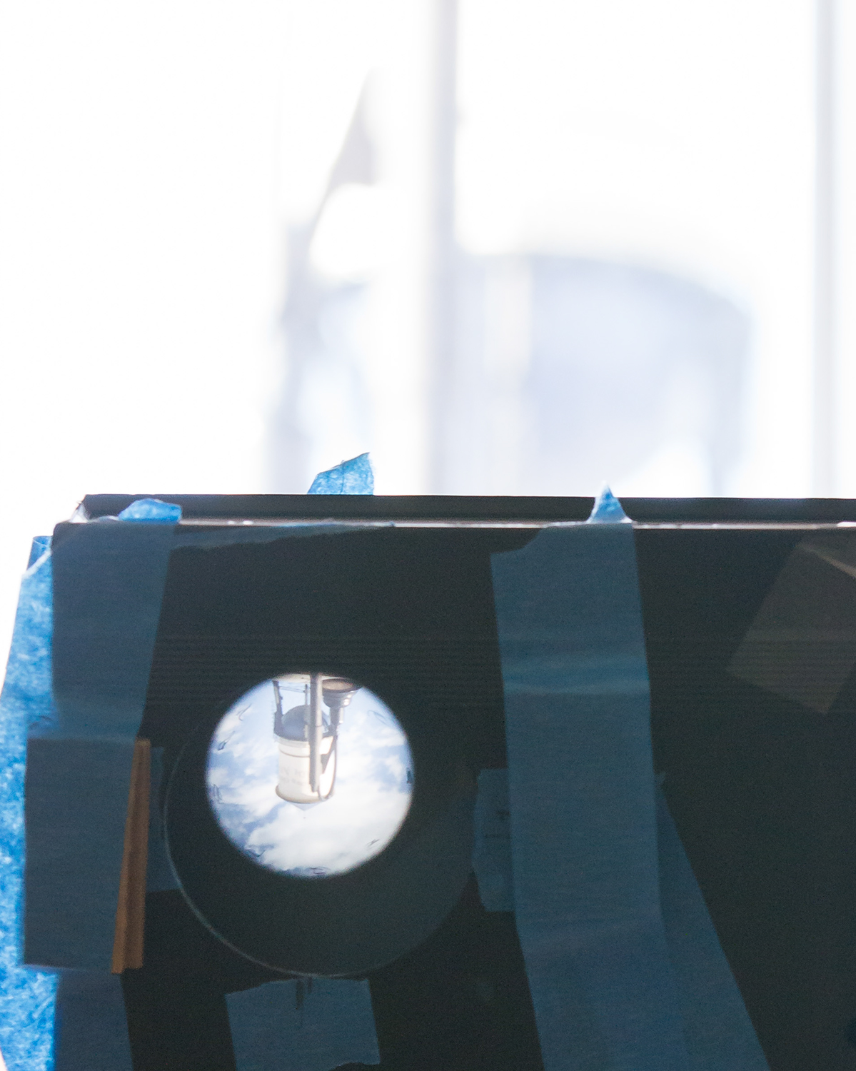
I used a plastic project box as the foundation for the system. A 2-inch hole saw made a hole that would accommodate the back of the extension tubes, which I set in place with a liberal application of hot glue.

The focus screen was a clear 5" Actobotics wheel. It took some experimentation to get it right. I'd initially sanded it down with progressively finer grits of sandpaper, scratching one of the surfaces, but leaving the other smooth. The progressive grits actually worked against me - with each successive grit, I was polishing it, making it more transparent. As it got polished, the image projected on it became less distinct. So I wound up falling back to 80 grit, and really tearing the surface up.
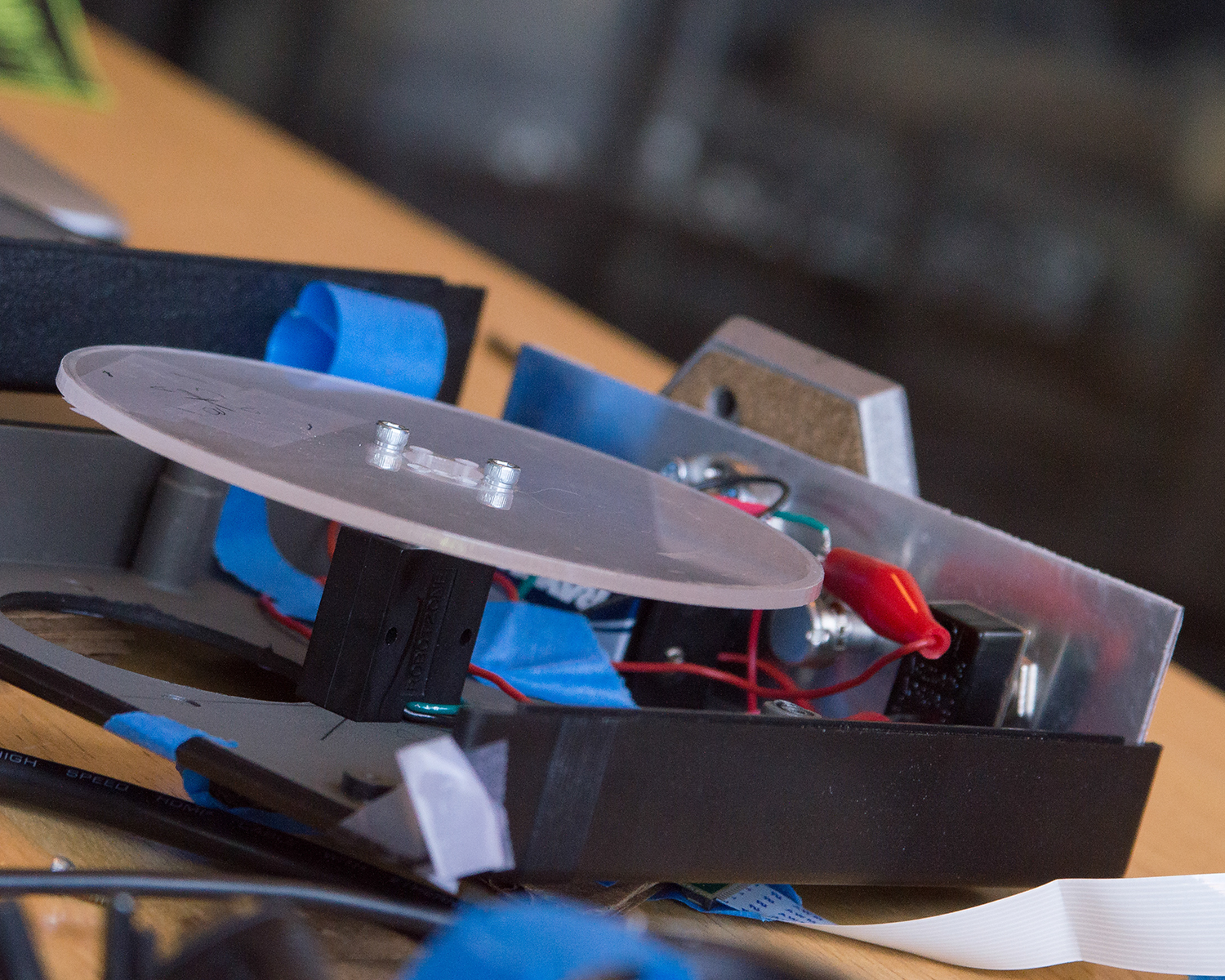
I mounted the disc on a small gearmotor, so it could spin. If the projection screen is turning, then the imperfections in the surface are blurred as it spins. It also lends an interesting old-time effect to the picture. The video below starts with an example of the wheel spinning up to show the difference.
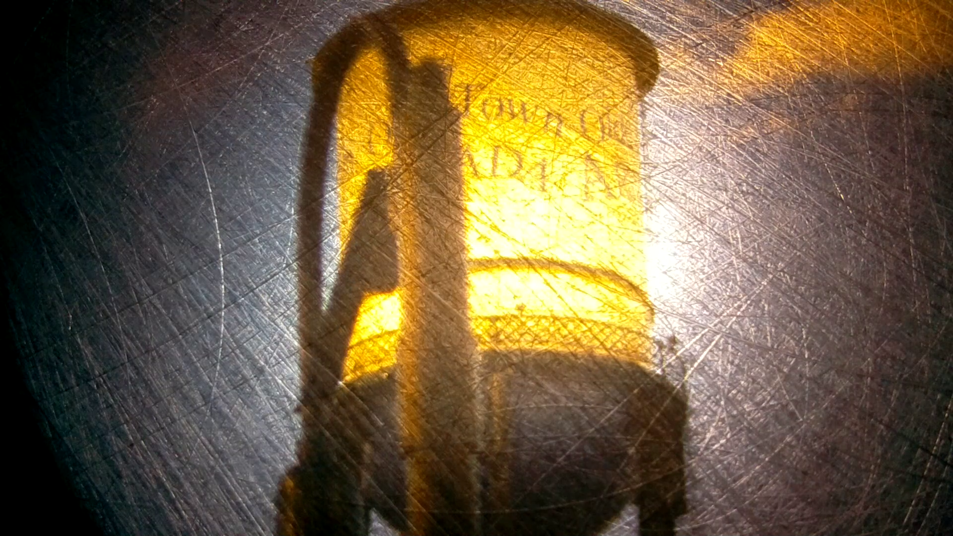
There are actually two systems that need to be focused at play here. The SLR lens focuses its image onto the wheel, which should be about 45mm behind the lens flange. The Pi Camera is then focused on the screen. I'd assemble the screen and lens, and use a star-pattern chart to set the focus. Then I'd add the Pi Camera, and run it in preview mode to get the field of view and focus adjusted. The scratched surface of the disc was actually fairly easy to focus on.
Out of the box, the Pi Camera is shipped with a hyperfocal distance of about a foot - everything farther away will be in focus. But some online research told me that the lens is actually threaded. Unscrewing the lens allows it to focus closer. If you try this, it takes two pairs of pliers - use one to hold the little box that the lens is mounted in (which is only attached to the PCB with doublesided tape), and the other to carefully grab and twist the lens. It took a few tries to get it into focus, and a few more tries to get it mounted at a suitable distance from the screen. I wound up with a stack of cardboard shims.
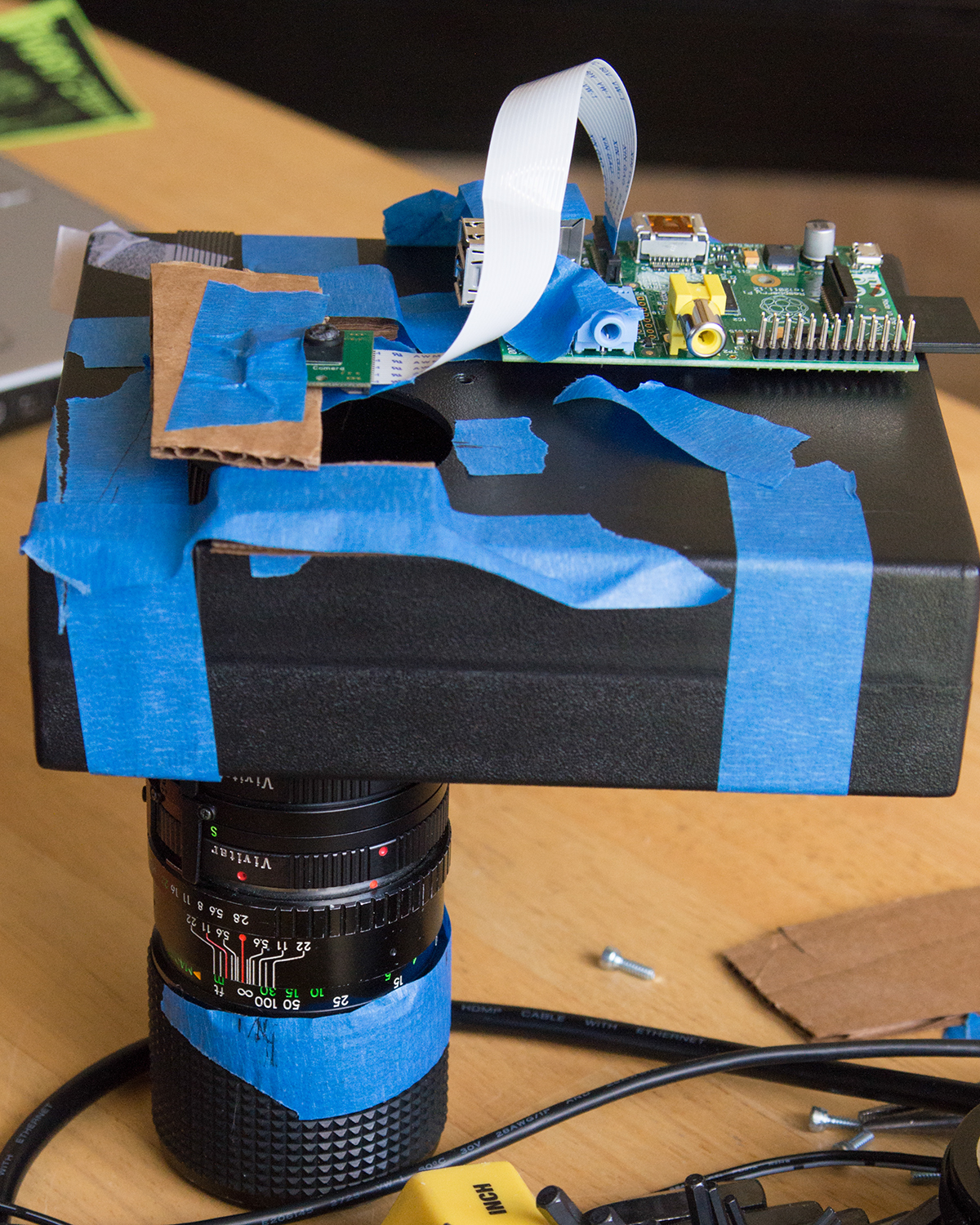
Forget duct, the universe is actually held together with blue tape.
It wan't pretty, but it was somewhat functional. The image still left something to be desired, though.
Removing the camera, and looking at the screen, I could see that my image was about 1.5" in diameter, and it seemed fairly evenly illuminated. But the image from the Pi Camera was heavily vignetted - the center was bright, but the edges were dim. I had a hot-spot problem.
I'm still not entirely sure what was causing the problem. It may be that the wheel was polarizing or collomating the light such that the sensor wasn't receiving it correctly, that all of the cascaded stages we just too dim for the sensor, or that I had a problem with the chief ray angle that was reaching the sensor. Whatever it was, I thought I'd keep experimenting.
Second Try, Part B
I'd been using a small scrap of vellum as a handheld focus screen while I was playing with the lenses. I decided to swap the wheel for vellum, to see if the results were any different.
Peeking into the box showed me that the image was about the size of a 35mm frame.
But the vellum still vignetted, though not as severely as the wheel.
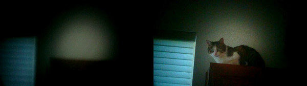
Spinning wheel (left) vs. Vellum (right)
Even with the vellum, the whole thing requires a lot of light - it was good in direct sunlight, but if even a few clouds went by, it was a lot less usable. If I can figure out the cause of the vignetting, that may change.
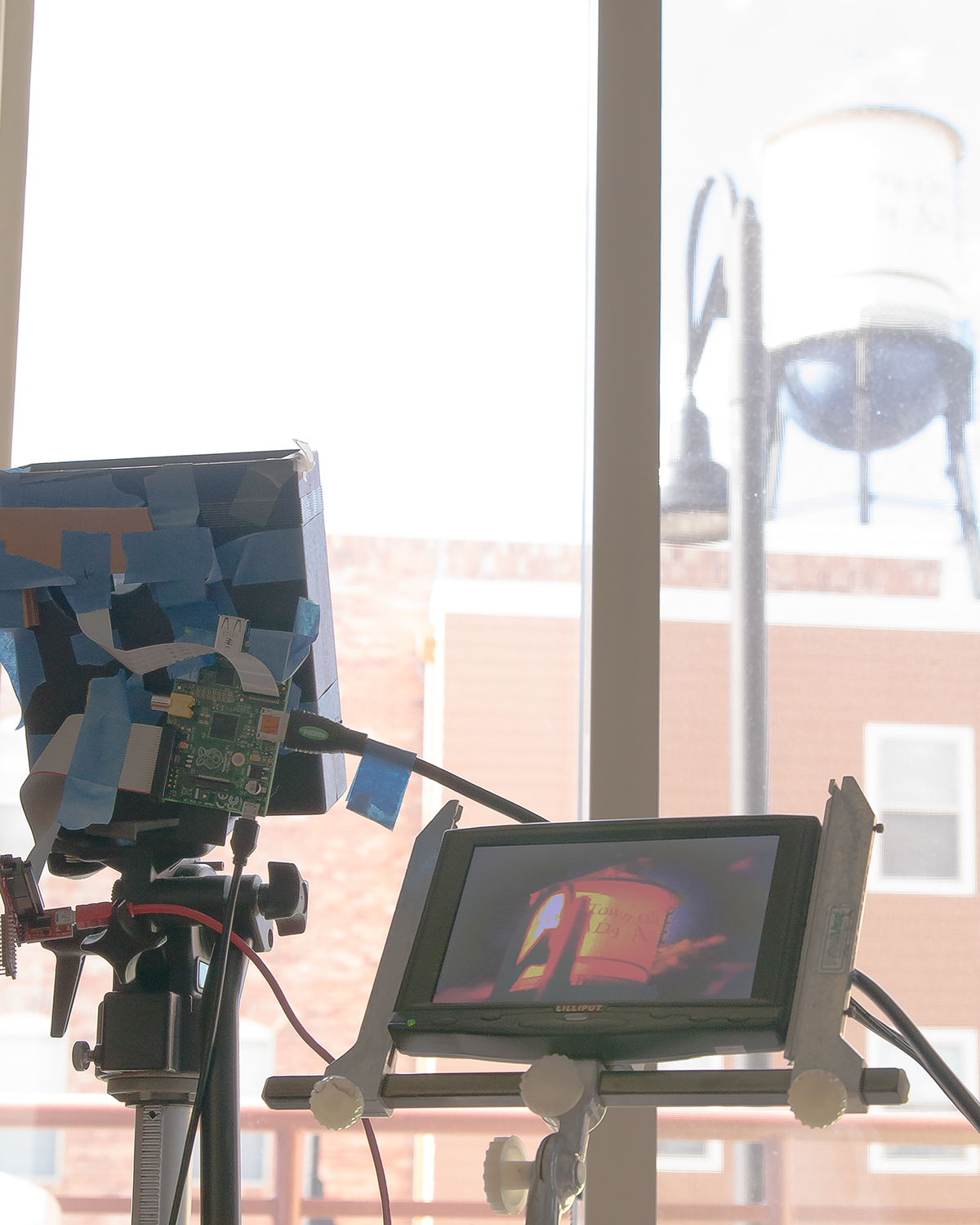
As it is, it's still a work in progress. I've been working with the command line versions of raspistill and raspivid, which are pretty cumbersome, but allow for a lot more control over the image than the little Kodak did. This isn't something that you're just going to pull out and start filming. I was hoping to get time to get Pi-Vision working, but I had a blog post to write...
Demo Reel
Here are a few clips that demonstrate what I was getting from the Pi Camera + DOF Adapter combo.
ReplaceMeOpen
ReplaceMeClose


I used to have a selectric with a bunch of solenoids added to the works to allow it to be used as a printer. There were a few companies back then that did those modifications, and IBM itself built consoles for some minicomputers (definitely the 1130) that used selectric mechanisms.
I didn't know that even we can customized a camera. I would like to have a reliable camera for my service office in Singapore (http://www.landedcondopro.com/). Can I used this for this purpose? Or I need to buy a new one..
"In optical terms, the region that is in focus is known as the “depth-of-field." Not exactly, but that's how people learn it. Depth of field should be more accurately referred to as depth of acceptably out of focus. Only one plane is ever in focus, the subject plane. Everything else is out of focus. There is a parameter called the circle of confusion, it is how large a circle a point is rendered. Somebody picks a COC based on what most people would consider "sharp". The COC for 35mm is smaller than for 4x5" film, since 35mm is usually enlarged a greater amount. But all this is splitting hairs.
For a given aperture, depth of field varies only with magnification. If you fill the frame with a flower using a wide angle lens, or use a telephoto lens and still fill the frame, the depth of field will be the same. What changes is the distance to the subject, and the angle of view (how much background you get). Again, just splitting some hairs.
I don't know what kind of typewriter you took apart as a child, but if it was full of solenoids, it wasn't an IBM Selectric. The Selectric 71, 1, and 2, were purely mechanical. Not electromechanical...just mechanical. And they make electronic engineering look like Lego's.