The Great Ceramic 3D Printer Experiment: Part IV
Follow along as I attempt to build a ceramic 3D printer using OS plans I found online.

Well friends, it’s been a minute since my last ceramic printer update. Today we’re going to continue on the extremely slow journey. Before we jump in, let's do a quick recap of where we left off. Feel free to also catch up on your own by checking out parts I, II, and III.
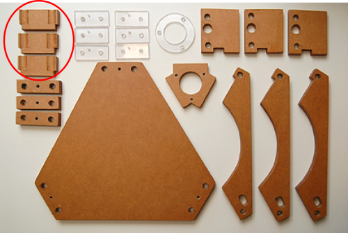
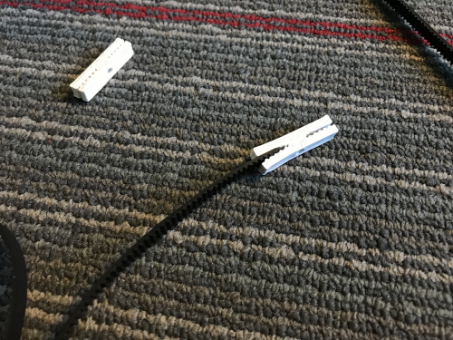
As a reminder, this project is based on Jonathan Keep’s OS Delta Ceramic 3D printer, and his documentation has been the main source of guidance as I move through this build. Last we spoke, I had completed the basic structure and was beginning to making things move. First and foremost, I needed to figure out how to make my own linear bearing attachments, which are circled in red below. Keep claims to have developed a custom tool to create that part, without much more information about it, so I knew I was pretty much on my own figuring this out.
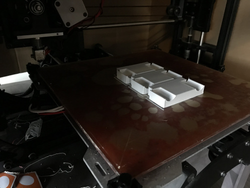
Given that I didn't have access to Keep's tools, I decided to 3D model and print this part, which is straightforward enough.
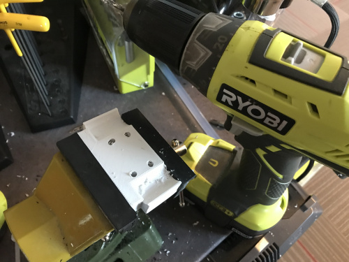
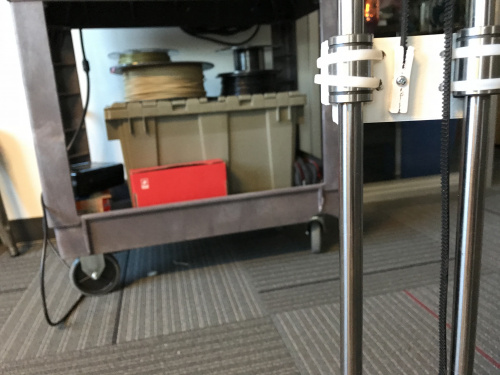
From here I needed to attach those fresh prints to the bearings, as well as to the belt for movement. I completely forgot to consider this in my model, so I drilled some holes in the prints to accommodate my zip ties.
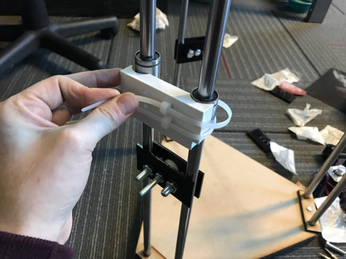
That worked well, and it was time to attach the belt. I realized that my belt is not already in a loop, and I had to find a way to not only clamp it into a loop, but also attach it to my linear bearings to create the movement I need. The solution I attempted, a 3D printed belt clamp, did not work very well. The grip on my belt was not strong enough, and it was awkward to attach two 3D-printed parts to each other manually.
That about brings us up to speed. In catching myself up on the project, I took a look at my 3D-printed parts, which I both drilled through and screwed together, and decided that my best bet is probably to re-model and re-print that part with more consideration to its function. Time be damned!
The beauty of 3D printing is that you can make a truly customized part; there’s really no need to start drilling holes or attaching parts together unless you are working against a deadline and literally do not have the time, which I am not. So it was back to the Tinkercad board.
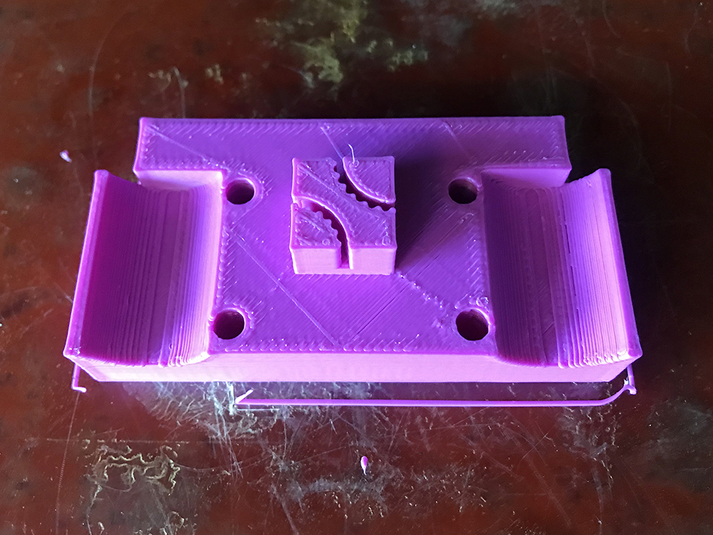
I decided I would model my belt clamp directly on the linear bearings attachment, eliminating the need to connect to parts together manually. I went to Thingiverse for some inspiration and was pleased to find that there are tons of GT2 belt clamps available for download, and the one I was using was not the only option. I found this really nifty square clamp and printed it out to test its strength.
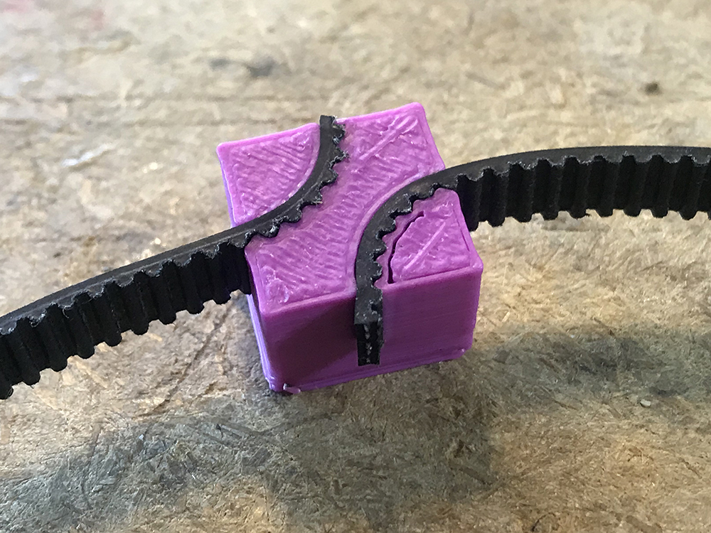
It proved to be a much more effective clamp than the one I was working with previously. With this knowledge, I decided to just pop that clamp on to my linear bearing attachment, and then add some holes for my zip ties as seen in the image below.
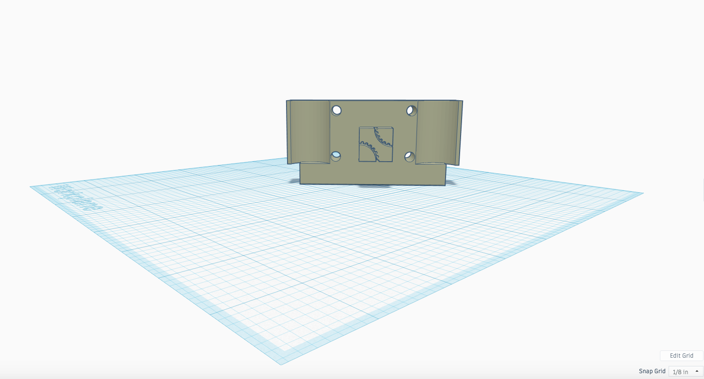
I was quite pleased with this because it solved three problems:
1. I now have room for zip ties; no need to drill through this print.
2. I now have a belt clamp, which will effectively turn my GT2 belt into a loop.
3. The clamp also effectively attached the belt to the linear bearings, allowing for movement.
In conclusion, I killed three birds with one print. Go me.
Previously, I attached these guys to the linear bearings right away. However, in reviewing Keep’s video, I noticed that before he zip-tied these into place on the linear bearings, he connected them via rods to the extruder holder in order to moved it using the belts on the motors (check out 2:21 in the video linked above). This led me to start looking at the base of my extruder holder more closely so that I could prepare it for the rods.
My initial attempt when I made the structure was cut out of two pieces of MDF, which I sandwiched together with wood glue. Upon further inspection, I noticed that Keep uses a second fabricated part to hold the extruder in place – a ring-like object, connected to the base of the holder via standoffs.
Keep's printer:
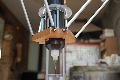
This is what I overlooked when I made my initial cuts, and I ran into a problem right away. My MDF was too thick for my longest standoff screws. I realized that I should just make these parts again to my own specs and decided to 3D print these parts too.
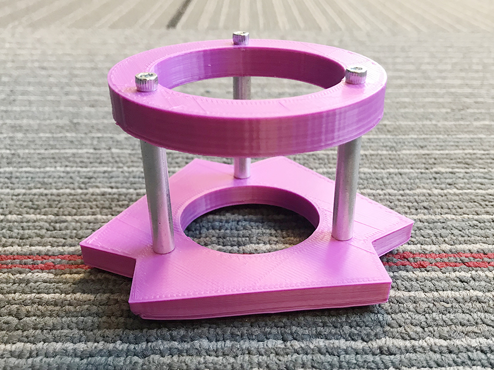
This worked really well. I was able to put together a little holder than keeps my extruder in position without wobbling, which I assume is the desired affect.
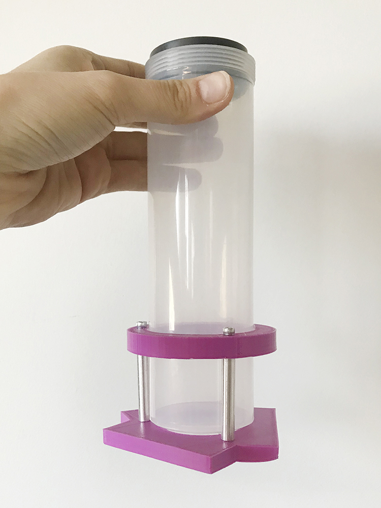
Now I can begin to work out connecting the rods. This is where I got stuck. In Keep's video, he uses small nails, making a secure but flexible connection between rod and MDF. Nails probably make a heck of a lot more sense if you are using MDF, but I printed my parts and I am concerned that the printed plastic won’t work quite the same way. Now I am pondering a way to move forward.
On one hand I feel like I should make the base of the extruder holder in a thinner MDF and drop the print, but that doesn’t solve how I’ll manage the linear bearing attachments, for which I am pretty committed to my 3D printed parts. Therefore, my next step will be to figure out how exactly I plan to work around that. I’d love to hear any suggestions you may have for this predicament in the comments below!
Before I close this post I want to mention that taking on a project well outside of my comfort zone has been a truly interesting experience. While I knew this would be a bigger project for me from the get go, I think I underestimated just how slowly I need to move through each step to figure out how to make this beast a reality. In the case of this project, I don’t have an intuitive feel about how to solve the problems I run into, but I am figuring it out as I go and learning so much along the way. I appreciate you sticking with me for the ride!


Since you are building a delta printer, you may find some insight looking at others out there. I have a Dagoma Neva 3D printer and it attaches the head using magnets. This might not be strong enough for the weight of your extruder but maybe it will give you some ideas. You can find the manual for it here: "https://dagoma3d.com/apps/help-center#!neva-user-manual"
Oh, that's a great suggestion! Thanks for the tip! :)
Hi Feldi!
As for taking on a big project outside your comfort zone, good for you! I grew up during the Space Race. When President Kennedy set the goal to land a man on the moon, there was a lot of technology that we needed that just plain didn't exist. For instance, integrated circuits were hardly a gleam in a scientist's eye. Today, we have things like the Raspberry Pi and the laptop computer I'm typing this on because we took on President Kennedy's challenge.
Thirty years from now, you'll look back on this as a wonderful learning experience. Regardless of whater you succeed or not in actually getting this thing to work, it's well worth the effort to try because you will gain a lot, both in knowledge, and in the confidence that you can face big challenges.
At the end of the day, that's what it's all about!
To connect your rods to your extruder holder (and also possibly the linear bearing holders), have you thought about bearings? I just checked at McMaster and they do have ball bearings that go mighty small (granted the price is inversely proportional to size...), even down to 40mil ID. I was thinking about the ball-joint rod bearing ends (they go down to 6-32 rod w/ 1/8" ID attachment), but you probably want to constrain the range of motion to one axis...
Nails are definitely not going to work in a printed part. My suggestion would be to add a hole that terminates in a slot that you can slip a nut into. This would be a form of captive nut design.
Just a thought if you are going to the trouble to 3d print the holder for the bearings why not 3d print something for the back side to hold them on instead of using zip ties? You could easily 3d print another piece that bolts on that would give a better hold than zip ties and would have a cleaner/more professional look.
I have a frame I can send you that should help with some of your issues.