Mathematical Color Fading
Chances are, you may never use all 16 million colors available to you with your RGB LEDs. But whatever colors you use, you should know how to smoothly fade from one color to another. And thanks to the wonders of math, now you can!

Color and Light
As a kid, I’m sure that we all learned about colors, the color wheel, primary colors and mixing colors, and most of us learned this with paints of some kind. But paint mixing is different than light mixing, in that paint is subtractive, while light is additive. The primary colors in the subtractive color mixing system are red, yellow and blue (known as the RYB set), and the primary colors in an additive color mixing system are red, green and blue (known as the RGB set). This is because those colors are found in the photoreceptors of the human eye.
If you really want to become a super color nerd, you could look into the work of James Clerk Maxwell, or, to dig a little deeper, even the work of Thomas Young and Hermann von Helmholtz.
So what all of that means is that when you paint a surface, for example red, the paint is actually absorbing all of the colors hitting it except for red. The same with blue paint, or yellow or green. Which is why, when you add all of the paint colors together, you get black. Your mixture is absorbing every color.
Conversely, with light, you are hitting a surface with color, so the surface simply reflects that color back. Shine a light with a wavelength of 700nm against a surface, and the surface will reflect that light, and you will see red. Which is why, when you add all of the colors of light together, you get white.

Pigment color wheel on the left; light color wheel on the right.
The concept of color changing
Now that you've read up on the Young-Helmholtz trichromatic theory of color vision (and I'm sure you have), you should have a little better understanding of how we can paint with light. It really just comes down to adjusting the percentages of the three colors - red, green, and blue - between 0% and 100%, to achieve the desired color. It would seem to be pretty straightforward stuff, and there are sites that will easily give you both the HEX value (which would look like #FF9999), and the DEC value (expressed as an integer of each color between 0 and 255, like (255, 153, 153)).
Since each of the three colors uses 8 bits, that is how we wind up with 256 possible values for each. While creating any of the 16,777,216 possible colors (256 x 256 x 265, right?) is easy, what happens when we want to smoothly fade from one color to another? There are a couple of ways to do this, so we're going to look at two options.
Sure it seems simple...
The first method is color fading at its most basic. We take our initial three values - red, green and blue - and adjust the numbers to our second values, so that they start at the same time and finish at the same time. As a simple example, let's say that your color fade was moving red by +120, green by +15 and blue by -40. Red would start to fade up, then once it got to three, blue would fade down by one; and once red got to eight, green would fade up by one. Back in 2007, Clay Shirky wrote a nice Arduino sketch to do just that. He used percentages of each color, and then converted them to the necessary 0-255 range. And this makes sense; we all get that we can adjust our LED outputs from 0-255.
/*
* Code for cross-fading three LEDs, red, green and blue (RGB)
* To create fades, you need to do two things:
*  1. Describe the colors you want to be displayed
*  2. List the order you want them to fade in
* DESCRIBING A COLOR:
* A color is just an array of three percentages, 0-100,
*  controlling the red, green and blue LEDs
*
* Red is the red LED at full, blue and green off
*   int red = { 100, 0, 0 }
* Dim white is all three LEDs at 30%
*   int dimWhite = {30, 30, 30}
* etc.
*
* Some common colors are provided below, or make your own
*
* LISTING THE ORDER:
* In the main part of the program, you need to list the order
*  you want to colors to appear in, e.g.
*  crossFade(red);
*  crossFade(green);
*  crossFade(blue);
*
* Those colors will appear in that order, fading out of
*    one color and into the next
*
* In addition, there are 5 optional settings you can adjust:
* 1. The initial color is set to black (so the first color fades in), but
*    you can set the initial color to be any other color
* 2. The internal loop runs for 1020 interations; the 'wait' variable
*    sets the approximate duration of a single crossfade. In theory,
*    a 'wait' of 10 ms should make a crossFade of ~10 seconds. In
*    practice, the other functions the code is performing slow this
*    down to ~11 seconds on my board. YMMV.
* 3. If 'repeat' is set to 0, the program will loop indefinitely.
*    if it is set to a number, it will loop that number of times,
*    then stop on the last color in the sequence. (Set 'return' to 1,
*    and make the last color black if you want it to fade out at the end.)
* 4. There is an optional 'hold' variable, which pasues the
*    program for 'hold' milliseconds when a color is complete,
*    but before the next color starts.
* 5. Set the DEBUG flag to 1 if you want debugging output to be
*    sent to the serial monitor.
*
*    The internals of the program aren't complicated, but they
*    are a little fussy -- the inner workings are explained
*    below the main loop.
*
* April 2007, Clay Shirky <clay.shirky@nyu.edu>
*/

// Output
int redPin = 8;   // Red LED,   connected to digital pin 9
int grnPin = 9;  // Green LED, connected to digital pin 10
int bluPin = 10;  // Blue LED,  connected to digital pin 11

// Color arrays
int black[3]  = { 0, 0, 0 };
int white[3]  = { 100, 100, 100 };
int red[3]    = { 100, 0, 0 };
int green[3]  = { 0, 100, 0 };
int blue[3]   = { 0, 0, 100 };
int yellow[3] = { 40, 95, 0 };
int dimWhite[3] = { 30, 30, 30 };
// etc.

// Set initial color
int redVal = black[0];
int grnVal = black[1];
int bluVal = black[2];

int wait = 10;      // 10ms internal crossFade delay; increase for slower fades
int hold = 0;       // Optional hold when a color is complete, before the next     crossFade
int DEBUG = 1;      // DEBUG counter; if set to 1, will write values back via serial
int loopCount = 60; // How often should DEBUG report?
int repeat = 0;     // How many times should we loop before stopping? (0 for no stop)
int j = 0;          // Loop counter for repeat

// Initialize color variables
int prevR = redVal;
int prevG = grnVal;
int prevB = bluVal;

// Set up the LED outputs
void setup()
{
  pinMode(redPin, OUTPUT);   // sets the pins as output
  pinMode(grnPin, OUTPUT);
  pinMode(bluPin, OUTPUT);

  if (DEBUG) {           // If we want to see values for debugging...
    Serial.begin(9600);  // ...set up the serial ouput
  }
}

// Main program: list the order of crossfades
void loop()
{
  crossFade(red);
  crossFade(green);
  crossFade(blue);
  crossFade(yellow);

  if (repeat) { // Do we loop a finite number of times?
    j += 1;
    if (j >= repeat) { // Are we there yet?
      exit(j);         // If so, stop.
    }
  }
}

/* BELOW THIS LINE IS THE MATH -- YOU SHOULDN'T NEED TO CHANGE THIS FOR THE BASICS
*
* The program works like this:
* Imagine a crossfade that moves the red LED from 0-10,
*   the green from 0-5, and the blue from 10 to 7, in
*   ten steps.
*   We'd want to count the 10 steps and increase or
*   decrease color values in evenly stepped increments.
*   Imagine a + indicates raising a value by 1, and a -
*   equals lowering it. Our 10 step fade would look like:
*
*   1 2 3 4 5 6 7 8 9 10
* R + + + + + + + + + +
* G   +   +   +   +   +
* B     -     -     -
*
* The red rises from 0 to 10 in ten steps, the green from
* 0-5 in 5 steps, and the blue falls from 10 to 7 in three steps.
*
* In the real program, the color percentages are converted to
* 0-255 values, and there are 1020 steps (255*4).
*
* To figure out how big a step there should be between one up- or
* down-tick of one of the LED values, we call calculateStep(),
* which calculates the absolute gap between the start and end values,
* and then divides that gap by 1020 to determine the size of the step
* between adjustments in the value.
*/

int calculateStep(int prevValue, int endValue) {
  int step = endValue - prevValue; // What's the overall gap?
  if (step) {                      // If its non-zero,
    step = 1020/step;              //   divide by 1020
  }
  return step;
}

/* The next function is calculateVal. When the loop value, i,
*  reaches the step size appropriate for one of the
*  colors, it increases or decreases the value of that color by 1.
*  (R, G, and B are each calculated separately.)
*/

int calculateVal(int step, int val, int i) {

  if ((step) && i % step == 0) { // If step is non-zero and its time to change a     value,
    if (step > 0) {              //   increment the value if step is positive...
      val += 1;
    }
    else if (step < 0) {         //   ...or decrement it if step is negative
      val -= 1;
    }
  }
  // Defensive driving: make sure val stays in the range 0-255
  if (val > 255) {
    val = 255;
  }
  else if (val < 0) {
    val = 0;
  }
  return val;
}

/* crossFade() converts the percentage colors to a
*  0-255 range, then loops 1020 times, checking to see if
*  the value needs to be updated each time, then writing
*  the color values to the correct pins.
*/

void crossFade(int color[3]) {
  // Convert to 0-255
  int R = (color[0] * 255) / 100;
  int G = (color[1] * 255) / 100;
  int B = (color[2] * 255) / 100;

  int stepR = calculateStep(prevR, R);
  int stepG = calculateStep(prevG, G);
  int stepB = calculateStep(prevB, B);

  for (int i = 0; i <= 1020; i++) {
    redVal = calculateVal(stepR, redVal, i);
    grnVal = calculateVal(stepG, grnVal, i);
    bluVal = calculateVal(stepB, bluVal, i);

    analogWrite(redPin, redVal);   // Write current values to LED pins
    analogWrite(grnPin, grnVal);
    analogWrite(bluPin, bluVal);

    delay(wait); // Pause for 'wait' milliseconds before resuming the loop

    if (DEBUG) { // If we want serial output, print it at the
      if (i == 0 or i % loopCount == 0) { // beginning, and every loopCount times
        Serial.print("Loop/RGB: #");
        Serial.print(i);
        Serial.print(" | ");
        Serial.print(redVal);
        Serial.print(" / ");
        Serial.print(grnVal);
        Serial.print(" / ");
        Serial.println(bluVal);
      }
      DEBUG += 1;
    }
  }
  // Update current values for next loop
  prevR = redVal;
  prevG = grnVal;
  prevB = bluVal;
  delay(hold); // Pause for optional 'wait' milliseconds before resuming the loop
}
Code by Clay Shirky, 2007
While this method is just fine for many (if not most) applications, it does have its drawbacks. Let's say your favorite sportsball team wears royal blue and gold as their team colors. It would be cool for your LED wall to fade back and forth between the two colors, right? But what happens to the overall color when it gets about halfway through to fade? Using this mathematical formula, at about halfway through the fade you wind up with your LEDs emitting (138, 132, 116), which is about the least interesting gray color possible. Additionally, it drops the brightness of the LED down to about half.
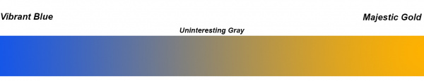
Mathematically accurate at its center, but a visual snoozer to be sure
Solving the issue with math!
Suppose that for your killer NYE party, which is always the most technologically advanced of any NYE party in your area, you want to fade your room lighting from Pantone's 2018 color of the year, Ultra Violet, to their 2019 color of the year, Living Coral (and I mean, come on, why wouldn't you want to do that?). Now you need to create a smooth fade from (95, 75, 129) to (250, 114, 104). We've learned that simply fading each of our three colors directly and simply can return some less than exciting moments through the middle of the fade, so how can we avoid this? By throwing a little trigonometry at it!

Pantone's 2018 and 2019 colors of the year. I think here at SparkFun we're just going to stick with red.
Now I know that even seeing the word "trigonometry" tends to elicit a fight-or-flight response from most people, but stay with me, this won't be that terrible. We're going to be using the sine function, but thanks to sin() within the Arduino IDE, we don't have to do much math at all!
Okay, we'll still need to do SOME math. Instead of using integers, we're going to use floating-point values. In Arduino terms then, instead of using int, we'll be using float, giving us the ability to use decimal points. This is important here, because A) we will be using things like Pi and radians, and will need numbers like 6.283, and B) sine uses a range of -1 to 1.
A quick sine primer
When you input a number into a sine function, you're actually entering an angle. By running the angle from 0 to 359 (remember, in a circle, 0° and 360° are the same, so if we start at 0, we have to end at 359), we complete one full circle, and our sine wave completes one full circuit.
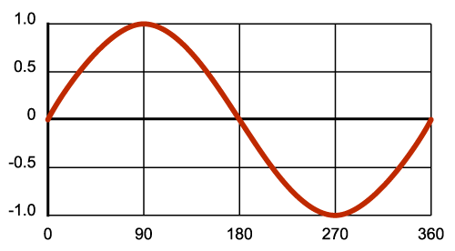
Degrees of a circle, and their corresponding sine wave
I mentioned that we were going to be using radians, and here's why. Sin() doesn't care about us and our degrees of a circle, sin() wants the information in radians. Since we know that a radian is a length on the arc of a circle equal to its radius, and that on any circle that equals about 57.2958°, and that it takes about 3.14159 radians to get halfway around the circumference of a circle, we can redraw our graph depicting radians just as our Arduino wants it.
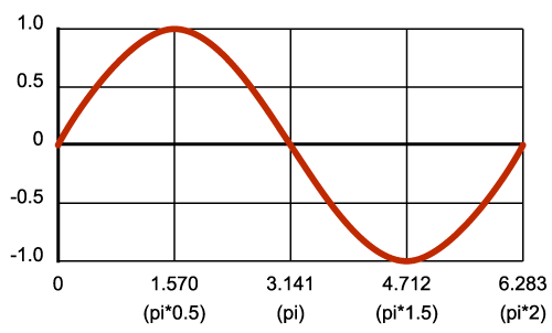
This is what a sine wave looks like in its natural habitat.
And finally, we know that our illumination range is from 0 to 255. We just need to map our output to meet this range. You may be familiar with the map() function in Arduino, but there's a simpler way to do this in our case. The most basic equation for sin() is:
out = sin(in)
We can take our sine range of -1 to 1, and adjust it to anything we want, with this line:
out = sin(in) * range + offset
So if we want want the output of our LED to be 0 (off), we would need an input of 4.712. Or, if we wanted our led at 255 (full power), we would need an input of 1.570. But what if we wanted to go from 0 to 255? Do we need to go backward? Not at all. Since our sine wave is continuous (or cyclical), we can continue counting forward and just add Pi to our starting number. Try running this code:
void setup(){

  Serial.begin(9600); //Setting up our Serial conection

}

void loop()
{
 // do input, etc. here - as long as you don't pause, the LED will keep pulsing
  float out;
  static float in = 4.712;
  if (in < 7.853){ // the sum of 4.712 + 3.141
    in = in + 0.01; // not the most efficient, just keeping it clear for demo purposes
  }
  out = sin(in) * 127.5 + 127.5; // this maps our sine wave, from -1 to 1, to out LED output, 0 - 250
  Serial.println(out); // prints the output
  delay(100); // just to give us a little breathing room
}
By watching the output to our serial monitor, we will see the numbers go from 0, when the input is 4.712, up to 255, when out input gets to 7.853. This gives us a little insight into how, when used for each of the three colors, this can give us a very nice, non-linear fade.
One thing to notice is the "static" modifier in the above declaration of "in." If we didn't use this, "in" would be initialized to 4.712 each time loop() loops, which would keep the LED output permanently at 0. By adding this modifier, you're telling the compiler to not keep initializing that variable every time we go through the loop.
This is just a small peek into color changing by doing more than just moving linearly from one output number to another. If we are really to examine color and how it is perceived by the human eye, we have a lot more digging to do on the subject. Next time, we'll not only play a little more with color changing with sine waves, but we'll also examine playing with HSV - that's hue, saturation, and value - to move through colors. Additionally, we're also going to look into CIELAB color space. Because as our parents learned watching Schoolhouse Rock, knowledge is power!
Interested in learning more about LEDs?
See our LED page for everything you need to know to start using these components in your project.


It is all how you look at it...
CMY are the primaries of printing, but that is based subtracting color of additive mixing. In which I mean, the pigments used are more of a filter, for light to pass thru, and reflect off the white background.
When we use RYB are primaries when you aren't tinting, but painting things.
RGB is when you add light.
Did this article get truncated? Was there supposed to be a part 2? This ends with some code showing how to map the output of the sine function to 0 through 255 (not 250 as the code comment says). But it doesn't say how the h*ck to use this knowledge in order to effect a fade from one RGB color value to another. Use the starting RGB as input to sine? No that doesn't sound right. Use arcsine (what's that?) to convert each of the the starting RGB tuples to radians, use sine to fade from starting values to ending values? Maybe, but how de we know how many steps the sine function will take us through for any two RGB values, so that we get to the new ending R, G, and B values at the same time?
So in simple words with FastLed how do I transition from pure green to blue with minimal intermediate colors? From green to red? I use CHSV(hue, 255, 255) hue increment from 96 to 160, lot of pale un-needed colors in between. Also decrementing hue from 96 to 60 produces unwanted yellows.Any way to avoid that?
I agree that each of the described colour systems are valid, both Rob's and other members'. However, if you're going to describe them as "additive" and "subtractive", then neither supplied diagram is helpful in explaining the two terms.
For "additive", the background should start as blacK (not White), then the Red, Green and Blue circles (adding/reflecting one colour), and where they overlap showing Cyan, Magenta and Yellow (adding/reflecting two colours), with the center being White (adding/reflecting all three colours).
For "subtractive", the background should start as White (reflecting all colours), then the Cyan, Magenta and Yellow circles (subtracting/absorbing one colour each), and where they overlap showing Red, Green and Blue (subtracting/absorbing two colours), with the center being blacK (subtracting/absorbing all three colours).
Note that I capitalised the relevant letters in each colour: the two most common colour systems are RGB (additive) and CMYK (subtractive).
Math and Color = Colorimetry/Color Science. See: www.rpdms.com/grafxscience/ for an easy understanding of the basic development in 1931 and earlier.
Fading RGB LEDs See: www.rpdms.com/ledinfo/ for details of basic rainbow fading development.
Great article. I recommend that your solution use a table of precomputed output values, then you won’t have to bother with floats, or recalculating the same values repeatedly at run time.
A couple of fine points on subtractive colors:
The subtractive primaries are cyan, magenta, and yellow, not red, blue, and yellow. (Hence CMY printers.) These are the secondary colors in your diagram of the additive primaries. Magenta pigments absorb green and reflect blue and red light. Cyan absorbs red and reflects blue and green. So when you mix the two pigments, the only thing that gets reflected is blue. This means the subtractive secondaries are red, blue, and green. Mixing red and blue pigments does not result in a bright magenta as suggested in your pigment color wheel, but in a dull purple. Mixing magenta and cyan pigments gives a nice blue.
This confusion continues in your example of the team colors. The dull gray in the middle would be true if you were mixing gold and blue pigments. The blue pigment would absorb everything but blue light, and the yellow/red pigment would absorb blue leaving nothing left. But if you are mixing LED light, the blue and gold (a mix of red and green light) would have all three primary light colors and would be whiter. Mixing two colors of light always results in a brighter, not a duller color. This will be more clear in your next installment on color spaces.
All of this is a bit tangential to your main point which is additive mixing, but as both artist and engineer, I like to help people better understand this fascinating subject.
The other thing worth noting is that the eye is more sensitive to green and yellow light than other colors. Because of that, as well as because of difference in conversion efficiency, you may need to adjust the current differently for different color LEDs to get a good color mix. In other words, 255 for your green LED may be 10 ma. where for your blue LED it might be better to use 20 ma. Again, this will be clearer in your next installment on color spaces.
While CMYK is used in offset printing and some desktop printers, RYB are the correct Primary colors for subtractive pigments. See: https://en.wikipedia.org/wiki/Color_wheel
gasstationwithoutpumps is correct. The subtractive colors (if, for example, you're printing with ink) are cyan, magenta and yellow. Often black and gray are added (when printing) into the palette, since using black directly is easier than printing all three (cyan, magenta and yellow) to get black.
Red, blue, and yellow are not subtractive primaries: cyan, magenta, and yellow are. Your subtractive Venn diagram is misleading.
https://en.wikipedia.org/wiki/RYB_color_model -
RYB is a valid subtractive color model. The problem is Rob-24601 has the wrong secondary colors. Should be Green, Orange, Purple.