Press a Button; Get Your Coordinates
Looking to get your feet wet with GPS? We've got just the tutorial for you! Accurately display your coordinates on a small OLED with the press of a button using hardware from our Qwiic Connect System (I2C).

 Here at SparkFun, our engineers have been quite busy in the GPS world. Over the last few months we have released some great new GPS Boards, including the extremely accurate GPS-RTK2 Board, the versatile GPS Breakout - ZOE-M8Q and the helpful GNSS Chip Antenna Evaluation Board.
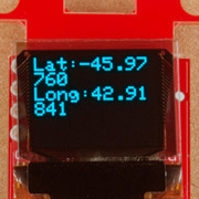
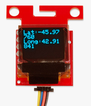
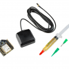
Individual needs for GPS projects can be very focused and specific, but there is one thing in common with all projects that use GPS modules - finding your location - and that's what today's tutorial is all about. Using the GPS Breakout - XA1110 and an Arduino board, 9V battery, push button and OLED display, you'll be able to simply push a button and see your coordinates. Think of this tutorial as a "hello world" for GPS.
Displaying Your Coordinates with a GPS Module
April 30, 2019
This Arduino tutorial will teach you how to pinpoint and display your GPS coordinates with a press of a button using hardware from our Qwiic Connect System (I2C).
Ready to get hands-on with GPS?
We've got a page just for you! We'll walk you through the basics of how GPS works, the hardware needed, and project tutorials to get you started.


Just a quick (pardon the pun) comment on the switch: Based on my nearly 50 years of "doing" computers, and more than that "doing" electronics (hey, back then there was no such thing as an LED circuit, other than maybe Bell Labs or IBM), I'd suggest either having a "pull-down" resistor on Digital Pin 2, OR put the C1 side of the switch to GND, and use mode "INPUT_PULLUP" on buttonPin (and you'll need to invert the logic on buttonPin). A long time ago, I ran into the problem of "floating" input pins not tending to low voltage, at least not very quickly...
There should now be an updated copy of the code with the revisions. Thank you for catching that!
Nice catch. Yeah, floating pins are not ideal and they have a mind of their own. The easiest would be to use the internal pullup resistor by setting the pin to an
INPUT_PULLUPso there are less pins to solder. Speaking from experience, all those pins adds up and can add a lot of time to a project. We'll be looking into it to update the two lines of the example code. =)