A Tale of Two Badges
Check out this behind-the-scenes look at Open Hardware Summit’s two different badges.

Due to official recommendations over coronavirus concerns in NYC, this week's Open Hardware Summit (OHS2020) has evolved into an all-digital summit. As event sponsors, it's a disappointment to miss out on seeing everyone and hearing some incredible talks in person, but we definitely understand, and either way we’re extremely proud of the electronic badges we helped create and assemble for this year's summit. For those who won't be able to see them in person, we thought we'd give you an inside look at how the two badges we helped create - a lanyard name badge and an open source, hackable wristwatch badge - came to be from start to finish.
Designing the Lanyard Badge
First up is the cool electronic name badge Nathan Seidle and Nick Poole designed. Nick describes the process:
After deciding that we wanted to design a name badge for the conference, Nate and I took to the whiteboard to brainstorm. We wanted the badge to be more interesting than a piece of paper in a plastic sleeve, but also not to compete with the wrist badge in terms of hackable features. The badge needed to perform the basic function of an event badge — to put your name in a place that people can see it — in a unique way. We considered various display technologies and design styles ranging from possibly underwhelming to prohibitively complex and expensive.
What we landed on was an elegant layout that resembles a conventional conference badge but also incorporates some fun PCB art techniques and gives us a chance to flex our automated design muscles. The final design would be a stack of three PCBs: A front layer that features the attendee's name as well as a blank space for writing a Twitter handle or URL, a middle layer to space the top away from the LEDs, and a rear layer with a number of battery powered LEDs to backlight the name on the top board.
This design would, of course, require us to customize each and every badge PCB to include the attendees' names: all 200+ of them. The rear two layers can be uniform across all badges but the front PCB needs to be unique to each person. Doing that layout by hand was entirely impractical, so we set out to automate the process as much as we could. I started by creating a prototype layout using my own name and those were ordered immediately to test the mechanical fit. Once the prototype design was verified, I removed my name from the prototype layout file to create a template. That template was saved as a 'design block" in EAGLE, allowing us to easily import the bulk of the layout to a new file as a single object.
Then we started in on software automation: I wrote a javascript tool that would ingest a list of names and return an EAGLE library containing each name as a footprint with the name cut out of the top mask and bottom copper layers. Each footprint also contained the proper rectangular mask-stop on the bottom layer and a central origin. At this point, I passed the baton to Nate, who wrote a series of EAGLE User Language Programs. The first one iterates through the library of name footprints and creates a new board file for each. It places the template design block into the layout and then adds the name block from the library and saves it before moving on to the next. Once all of the files are generated, a second script iterates through each board file and generates gerber files which are bundled into .zip archives ready to send off to the board house. The only part of the process we couldn't automate was ordering, so each gerber file was submitted by hand to JLCPCB. Next time, we'll build a browser extension to automate that too!
As we started to get boards in, I started to experiment with different configurations of LEDs. The original rear PCB design had 8 evenly spaced 0603 LED footprints, each with its own current limiting resistor. The 0603 LEDs seemed to have too narrow a projection angle which caused harsh bright spots in the backlighting. Increasing the current-limiting enough to soften these hotspots ended up making the light too dim to be noticeable in a well-lit room. At this point, we were already approaching the project deadline (because of manufacturing delays due to Lunar New Year and then the Covid-19 outbreak) so Nate ordered a few options for LEDs while I designed a final rear PCB that incorporated a greater number and variety of LED footprints that would accommodate whichever arrangement of LEDs tested the best.
In the end, we found that the CREE warm white J-Series LEDs were cheap, bright and well diffused. The warm color-temperature also made the light more efficient because the yellowish color of the PCB substrate rejected a lot of the light from cool-colored white LEDs. In the end, some hotspotting was unavoidable without the use of expensive, side-firing LEDs or diffuser materials, but we were able to reduce it to a manageable level that leaves the name legible at a distance.
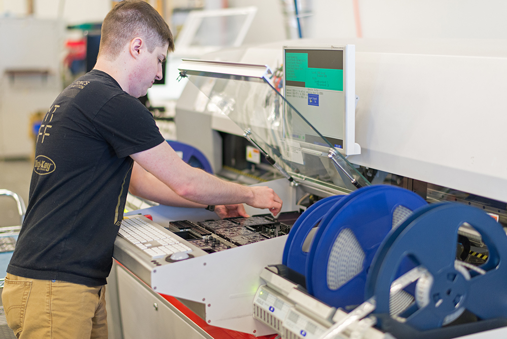
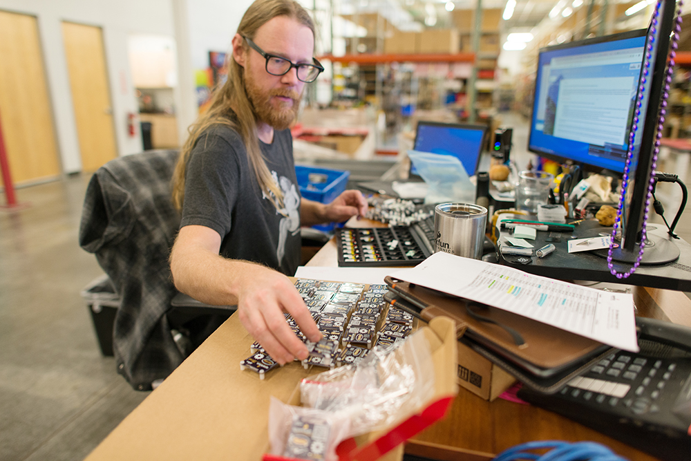
Assembly day was all-hands-on-deck in SparkX. The process looked like this: First, the rear-PCBs were solder-stenciled and all of the LEDs and resistors were populated using our desktop pick-and-place machine. While those boards were in reflow, the panels of middle-PCBs were broken apart and the mousebites were sanded smooth. When the rear-PCBs returned from reflow soldering, they were each tested and reworked as needed. We were required to order a minimum of 5 front-PCBs for each name, so each attendee's 5 PCBs were bagged together and alphabetized for final assembly. The least blemished of these 5 boards was chosen for each name and then stacked with the two other PCBs. The stack was secured with binder clips while the four castellated holes were soldered together to finish off the badge. The binder clips come off and the finished badge goes back into the bag with the other 4 copies of the name PCB. Finally, each badge got a CR2032 coin cell with a pull-tab to prevent the battery from dying in shipping, as well as a custom lanyard.
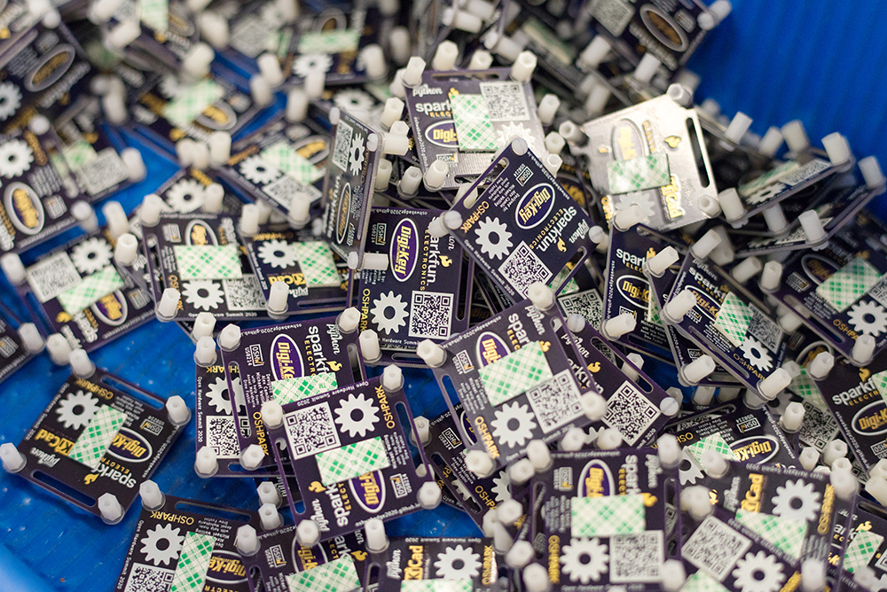
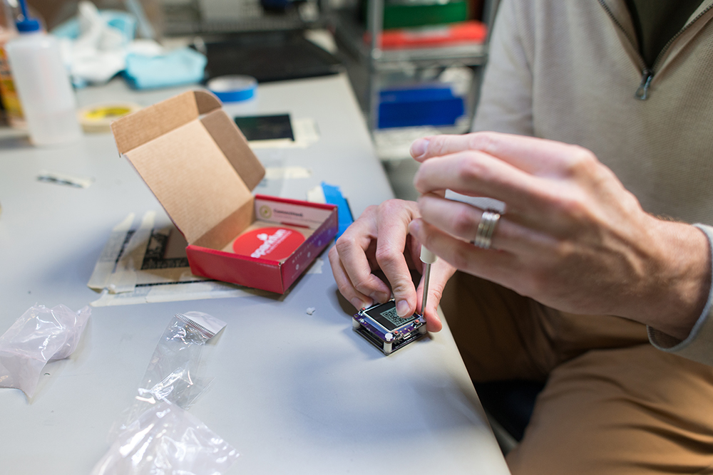
Wristwatch badge
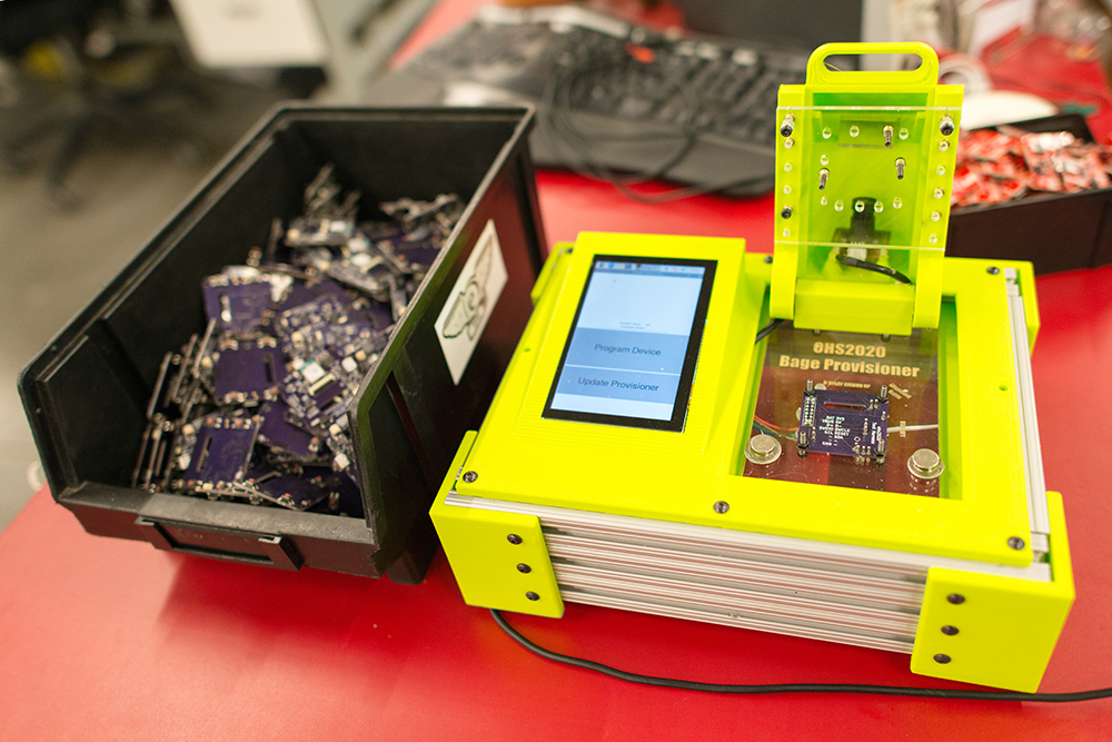
We also helped get another set of badges together for OHS2020 - the awesome wristwatch form factor "badge". The badge was developed by Michael Welling, Alex Camilo and Drew Fustini. The badges represent a great partnership with various companies pulling together to help get them built. Digikey provided parts, OSH Park the PCBs, and SparkFun did the assembly. You can read more about the tech inside here.
Check out the photos below for a behind the scenes look at the assembly process!


Glad I read today's blog (a bit difficult as I need to stop by the store a bit later and get some "reading glasses" -- after my eye surgery yesterday and a week ago yesterday [one eye at a time], I have 20/20 distance vision [good year for it!], but bad close vision). Anyway, I hadn't heard of JLCPCB -- the only two PCB manufacturers I have done business with (that are still in business) are Gold Dragon and OSH Park.
Glad I glanced at the OHS2020 website as well -- looks like there are some interesting links amongst the supporters. (Glad to see some of my favorite companies among the supporters -- SparkFun, DigiKey [been a customer since 1973], and Adafruit!)