- Home
- Product Categories
- RF
- SparkFun Transceiver Breakout - nRF24L01+ (RP-SMA)

SparkFun Transceiver Breakout - nRF24L01+ (RP-SMA)
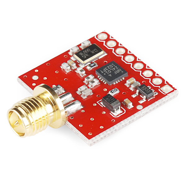
The nRF24L01 module is the latest in RF modules from SparkFun. This module uses the 2.4GHz transceiver from Nordic Semiconductor, the nRF24L01+. This transceiver IC operates in the 2.4GHz band and has many new features! Take all the coolness of the nRF2401A and add some extra pipelines, buffers, and an auto-retransmit feature - very nice!
This board features a reverse polarized SMA connector for maximum RF range. Please remember, you will need a mating RP-SMA 2.4GHz antenna (listed below).
Because of lower costs and better performance, we recommend the nRF24L01 over the original nRF2401A modules.
This unit has an onboard 3.3V regulator and has 5V tolerant IO lines. This makes it very flexible, but you will need to power the unit with 3.3V or higher voltage for the regulator to perform properly.
Note: We now populate these boards with the nRF24L01+. The '+' version of the IC has improved range, sensitivity, and data rates. The command set is backward compatible with the original nRF24L01.
- On-board 3.3V LDO Regulator (3.3 to 7V supply allowed)
- Reverse Polarized SMA Connector for external 2.4 GHz Antenna
- Up to 100m Range at 250kbps with appropriate antenna
- 250kbps to 2Mbit Data Rate
- Auto Acknowledge
- Auto Re-Trasmit
- Multiceiver - 6 Data Pipes
- 32 Byte seperate TX and RX FIFOs
- 5V tolerant input pins
- Software selectable channel from 2400MHz to 2525MHz (125 Selectable channels)
- Minimum number of external components
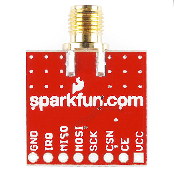
- Pins broken out : VCC, CE, CSN, SCK, MOSI, MISO, IRQ, GND
- Lots of application notes and support on Nordic Semiconductor Website
- Schematic
- Eagle Files
- Hookup Guide
- Nordic VLSI website
- nRF24L01 with RPSMA Dimensional Drawing - Please note this does not show the RP-SMA connector
- nRF24L01 Datasheet
- Great Nordic tutorials
- mbed Example
- Example PIC Code
- GitHub
SparkFun Transceiver Breakout - nRF24L01+ (RP-SMA) Product Help and Resources
nRF24L01+ Transceiver Hookup Guide
July 30, 2015
A basic getting started guided to the SparkFun Transceiver Breakout - nRF24L01+
Core Skill: Soldering
This skill defines how difficult the soldering is on a particular product. It might be a couple simple solder joints, or require special reflow tools.
Skill Level: Noob - Some basic soldering is required, but it is limited to a just a few pins, basic through-hole soldering, and couple (if any) polarized components. A basic soldering iron is all you should need.
See all skill levels
Core Skill: Programming
If a board needs code or communicates somehow, you're going to need to know how to program or interface with it. The programming skill is all about communication and code.
Skill Level: Rookie - You will need a better fundamental understand of what code is, and how it works. You will be using beginner-level software and development tools like Arduino. You will be dealing directly with code, but numerous examples and libraries are available. Sensors or shields will communicate with serial or TTL.
See all skill levels
Core Skill: Electrical Prototyping
If it requires power, you need to know how much, what all the pins do, and how to hook it up. You may need to reference datasheets, schematics, and know the ins and outs of electronics.
Skill Level: Rookie - You may be required to know a bit more about the component, such as orientation, or how to hook it up, in addition to power requirements. You will need to understand polarized components.
See all skill levels
Comments
Looking for answers to technical questions?
We welcome your comments and suggestions below. However, if you are looking for solutions to technical questions please see our Technical Assistance page.
Customer Reviews
5 out of 5
Based on 3 ratings:
1 of 1 found this helpful:
Best RF24
I have been trying for years with various versions of RF24 to get a stable communications running. This works and I had it up for hours and it did not miss anything.
I have written basic code to control a servo from a slider pot on another one. Command to Slave is here enjoy: https://github.com/alohawild/RF24
The breakout board is good but you will need to get the soldering done yourself. Pretty standard equipment .
Is this compatible with the Arduino Nano? If so how would the set up change?
Hi there, it sounds like you are looking for technical assistance. Please use the link in the banner above, to get started with posting a topic in our forums. Our technical support team will do their best to assist you.
Feel free to check out the hookup guide for more information on this product.
Does anyone know what Ls value I should use for determining the Tpd2stby delay? (Table 16 of the nRF24L01P datasheet) Thanks
I was reading the data sheet and it says that it is important to not keep it in tx mode for more than 4 ms, is this just due to FCC regulations? Or will it damage the unit?
Is there any design Files for this product
Would love to get my hands on the Eagle files for this, especially the board layout. The schematic and board layout are available for the chip antenna version, so you might have some luck with that design, and the photo of this one for layout.
Folks be very careful with sparkfun on economy light shipping. The dont mention it, but they don't take any responsibility or provide any guarantee that the item will reach you. ( its not about time as it mentions its also no guarantee throw and forget shipping ) , heres my story with facts :
My order number : 954563 ( (April 20, 2014) ) , Total Value : 85.65 $ ) , Shipping Method: Economy Light
and here's the tracking number on USPS : 92748924911461551000498179
USPS , never delivered it, and then said it caem and i was not there and ready for pickup in a post office that is 11 miles away. I went there, but the pack was not there in post office, they said they will look into it promptly and get back.
I contacted sparkfun and all i requested was for help from their side to check and see, call usps, take some responsibility. But nothing. They bluntly said , you choose free shipping, it is upto you, you get your post or not.
and then I ended up raising a official case with usps, and they got scared and shipped the package back to sparkfun, ( you can see the fun if you go to usps track and confiirm and enter the above tracking number )
here is the reason usps gives :
Your item was returned to the sender on May 2, 2014 at 12:12 pm in WESTERVILLE, OH 43082 because the addressee moved and left no forwarding address.
All this, while i am in the SAME EXACT address, and i woudl surely know if i had moved !
So much for a company which advertises that its speciality ,its communiyt and for project people. whats the problem here , basically the following :
ITs not worth it folks, they might have started with good intentions of being a speciality shop, but buying such circuitry from big organizations protects you in many ways and atleast wont pull the plug.
If they had called up usps, and did some pushing as a seller and a sender atleast it woudl have been better.
Now i only hope they dont eat away my money too, and refund me on the return of package. they themselves can go and track and see the usps status.
ifthis is the fate of small business here, i can see why people prefer big online retailers, who safegaurd every dollar buy !
very sorry !
Can this be used with a Raspberry Pi? I want to create an RC Rover and I want to connect it with my old E-flight LP5DSM Proportional 5 Channel Transmitter with SPECTRUM 2.4 GHz DSM Technology. How can I pair the transceiver and the transmitter?
I'm reading over the data sheet and maybe I'm missing something, but my understanding is that when a packet comes in it triggers an interrupt, at which point you can ask what pipe the received packet is for, and start reading the payload over SPI, however it goes on to say you should clear the interrupt and repeating reading the RX FIFO until it's empty, saying nothing about waiting for another interrupt. Wouldn't this make it imposable to know what pipe that data was for? Since you can't trust the pipe info in the status register except on the high to low transition of a interrupt.
If I just pop a payload every RX_DR (rx data ready) then what is the point of having a FIFO at all?
Hi, I wanted to know how to power these up . I heard if we power through the arduino the current is limited and the modules dont work well at long distances as the power supplied to the module is low. Any ideas on how to supply it power. Any adapter with 3.3 ~ 7 V rating will work?
Can someone tell me if there are any advantages to this one over the one below? besides the 3.3V regulator.
http://www.dx.com/p/nrf24l01-pa-lna-wireless-module-w-antenna-black-3-0-3-6v-222913#.UzJkCVeGN5E
Because the one in the link is cheaper and seems to have much longer range at all frequencies, includes an antenna and soldered headers.
Does anyone know if there's any RF leaking from the transmitter when its in RX mode? I'm looking to set up a wireless system in an RF sensitive environment, and need recievers that will sit quietly until triggered by an incomming start transmission.
I noticed that there are holes for the output and input pins. How would I wire it into a microcontroller like arduino without using solder?
Well, you're going to have to use some solder, at least to put in a female header. Then you could use jumper wires to connect to the Arduino.
How long does it take to ship?
Does this require an external power supply? I'm try to make it working with this module http://www.seeedstudio.com/depot/nrf24l01module-p-1394.html?cPath=19_22 and no luck at all after 5 hours. i checked the pin connections (and then re checked, and one more time).
I'm using the sparkfun arduino pro mini to drive the modules with the RF24 Library (also tried with the seeeduino, and one mega).
Edit: got it working. the problem was the power supply for the 'regular' nrf24l01+. I'm using one of this connected to my RPI communicating with some pro minis! works GREAT!
I am planning to buy this module, but I dont know which antena is compatibile with this module 2.4GHz Duck Antenna RP-SMA or 2.4GHz Duck Antenna RP-SMA - Large? Thank you.
Both are compatible. The only difference is the range you'll get out of them and the length of the antenna.
I'm having some problems getting this module to work. I've tried some sample code online, and for some reason can't get a response from the module. Is there an easy way for me to make sure that the module is actually functioning properly independent of my code?
I used this product to build a Wireless Guitar Transmitter for my senior project! It worked awesome, I was able to transmit 16-bit samples at about 28,000 samples per second. I even got a range of over 10 feet, which is impressive for this little guy running at the 2Mbps air data rate. Highly recommend this product!
how do u manage to get that high of a bitrate? :O i m using 2 pipes sending 8bit data on both of them and amm, it laggs pretty much :O will try rewriting the code over the kiel RTX kernel,
http://youtu.be/f9W1dbcs5Cc of my setup
These seem to be quite nice, but... well they don't work reliably.
I have set up two identical boards to do simple transmit-receives and display the results on 2-line displays. The results are not good. Initially transmission works, but at random points the transmission just stops working, as if there were heavy interference. However the transceivers are right next to each other, and I live in the country away from large populations of wifi.
I cannot really work out what the problem is. I've tried both the "Mirf" code, and my own driver, written with reference to the data sheet. Both exhibit the same effect. It seems to happen more with high speed transmissions, and I've tried various settings (enable/disable CRC, auto-acknowledge, etc) with no luck. All the device registers are consistent with out-of-range conditions.
It's a shame because these are quite cheap, but I'm pretty sure I've done nothing wrong, so I much recommend avoiding these.
Another reason you might want to avoid them: there are a few annoying architectural decisions (e.g. it doesn't automatically go into receive mode after transmitting like you'd expect, and the ack-payload behaviour is pretty badly documented (or maybe it really is as random as suggested)).
my works without problem after disabling autoack on both! , before that i had experienced same difficulties
Hey guys, You better wake up your QA department you're sending out these little guys with the wrong body parts. I think the reverse polarized SMA connector got reversed. The RP-SMA connector has a female center just like the antenna i want to connect it to.
Is it different than the pictures?
Yes. It has an external thread with female center (no pin).
Very strange! I just checked all of our stock and they are all accurate to the picture (except for red PCBs). Contact cservice@sparkfun.com and they can get you a new board. Sorry about that!
I have the red one. What's the difference? Other than the connector.
red one has a red PCB, that's all. It's just a different color. What probably happened was that there was a wrong connector in the box during assembly. The way we test, it would have tested ok (using a jig and such), because the connector didn't get used. In a build of several hundred, it unfortunately probably got looked over.
Just received my replacement part with the correct SMA connector. Thank you Sparkfun.
You're welcome, sorry for the mix-up. It happens from time to time.
I wanna Know when you will be getting more tranceivers? I need at least 50 of then. thanks.
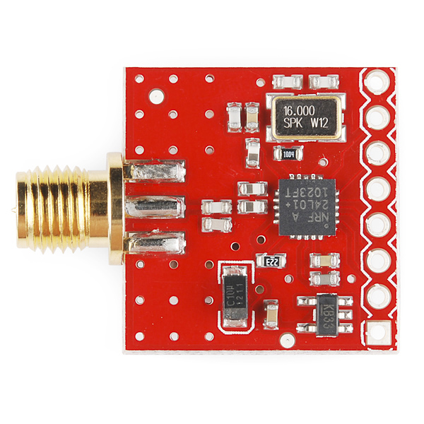
I've received a few of these modules, and while some have the 1M resistor marked 1004 across the crystal (which the data sheet says is not really necessary), 3 other modules have a resistor marked "310" across the crystal.
31 Ohms is a long way off 1M ohm. Is there any reason for this?
Is an "nRF24L01+" used on this board or the old "nRF24L01" IC?
In the picture it is the old "nRF24L01" and datasheet link is the same!
Thanks.
hi..
im using nrf24L01+ tranceiver.
in the transmit part im bit confused. i refered the sample code. after "cmd = 0xA0;" we are selecting 4bytes. 0x34,0x33,0x32 and 0x31. but im wondering how do i find these values in the data sheet. also i need to transmit some data. we supposed to transmit data after the command 0x0A. am i right?? cn anyone plese help me??
thanks
Does anyone have a recommendation for a supplier for an extension cable to run between the transceiver and the antenna?
I'd also appreciate your views on maximum cable length, if you have any you'd like to share.
This guy I found makes custom cables and does a fantastic job.
Hello ,
I have a project that is using Transceiver nRF2401A with Trace Antenna.
Now am Planning to use this Module, I am new bee I could see command set is backward compatable, can someone let me know how do I match the Pins between these two,
Next board revision, it would be nice to run this off 3V, in other words bypass the Vreg.
Is this transceiver going to be in stock anytime soon? I am planning on using this transceiver in my senior project and would like to buy a couple of them as soon as possible.
Thanks
can't speak to the range of the nrf24L01 but I just tried a pair of nrf24L01+, one with chip antenna the other with this RP-SMA & the 4" duck antenna. At 250Khz and 0Dbm, outdoors with a clear line-of-site I got just about 75 meters (measured by pacing, YMMV).
Tried the old nrf24L01 and the new nrf24L01+ model but the range for the new model is poorer...anyone can verify? On visual inspection, notice one capacitor may be different. Would it affect the range?
Has anyone upgraded one of these to the nRF24L01+ chip? Thanks!
We have the nRF24L01+ in stock. I'm not sure if we've run through the old stock yet. I'll find out what chip we actually have on there.
When you do run out of the original stock, I would suggest removing the 1M resistor across the crystal - The datasheet says it's not required on the +.
Cheers,
Allan.
Could you guys post the schematic for this board?
For now, I'm assuming it is substantially the same as the "Application Example" on page 37 of the chip spec sheet, but with the addition of a 3.3V regulator on the VDD line.
Thanks,
- Dean