- Home
- Product Categories
- Cellular
- ADH8066 Evaluation Board

ADH8066 Evaluation Board
Replacement:CEL-10741. We've made some minor changes to this board to facilitate hardware flow control. This page is for reference only.
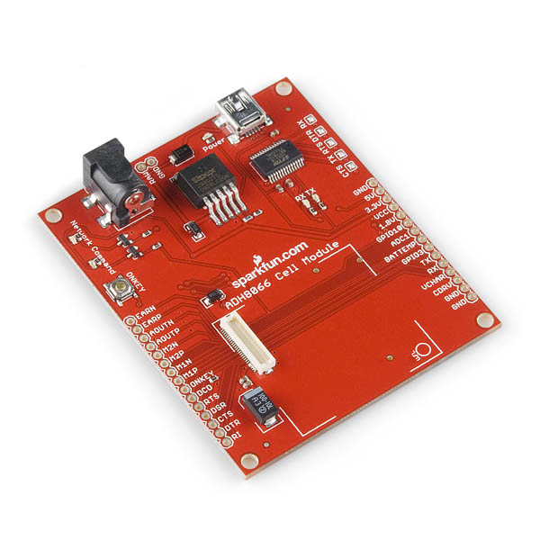
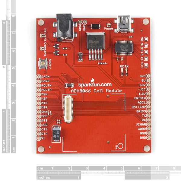
The evaluation board for the ADH8066 Cell Module breaks out all the pins to the module and provides you with the necessary support hardware to get you up and running. The ADH8066 board attaches to any USB port and appears as a standard com port. Power up the board with 6-12 VDC, turn on the module, and you can start sending and receiving AT commands via HyperTerminal or your favorite terminal program.
The board comes assembled as shown so you don't need to mess with soldering the 50-pin narrow pitch connector.
Note: To turn the unit ON to send commands, the ON/OFF button must be held down during power-up until the 'Command' LED comes on. See datasheet below for more information.
Note: Some USB ports cannot source enough current to power the ADH8066 module. If the power supply is inadequate, the module may shut down while attempting to connect to the cellular network. An external power supply will correct this problem if it is experienced.
- Schematic
- [Eagle Files](http://www.sparkfun.com/datasheets/Cellular Modules/adh8066_eval-v11.zip)
- Datasheet (ADH8066)
- AT Command Reference Manual
- Enhanced AT Command Reference Manual
- Hardware Application Notes
- Software Development Guide
- Firmware Update
Comments
Looking for answers to technical questions?
We welcome your comments and suggestions below. However, if you are looking for solutions to technical questions please see our Technical Assistance page.
Customer Reviews
No reviews yet.
I'm having a problem. Once I got the board working using the power and usb connections, I began to eliminate pieces of the evaluation board with the goal to ultimately run tx/rx through an arduino. Using the test schematic for the ADH8066 Breakout Board, I've been able to replace the usb with a FTDI Basic board connected to TX, RX, & ground. (DSR & DTR jumpered).
For this configuration, I've been able to have the board boot successfully by powering the board (using the power jack on the evaluation board), then holding the ONKEY button for a couple of seconds. The green Network LED then goes out, and after 5-10 seconds, lights up again. At this point the board is functional.
My problem is when I try to power the GSM module through an external Vbat. I'm powering the module using a 4V regulated supply connected to VCC. When I do this (at this point neither the power or the USB connectors onboard are being used), a) Command and Network LEDs light upon powerup, b) Network light turns off with ONKEY button, and then c) the network LED never re-lights, and the module appears to be off/not listening.
Am I doing something wrong, or is there a reason why this cannot be done using the evalutation board? Thanks in advance for any help you can provide.
I believe there is an error with the board. Pin 3 (RTS#) of the FT232RL (Output) is connected to pin 37 (RTS0) of the ADH8066 (also an Output). Shouldn't it be like this:
FTDI 11 (CTS#) to ADH 37 (RTS0)
FTDI 3 (RTS#) to ADH 34 (CTS0)
And I think
FTDI 2 (DTR#) to ADH 35 (DSR0)
Has anyone gotten hardware flow control to work on this board? Honestly the data sheet is terrible. I am considering a different module.
Yes, you are correct, thanks for catching that! The hardware flow control pins are not hooked up correctly. However, if you are not using the FTDI on board, you can use hardware flow control externally or just use the board without handshaking.
We will get this fix into the next revision. Also, if you have any questions about the module, feel free to email techsupport at sparkfun dot com.
Sorry about that.
Firmware update link is down?
Working wonderfully with external power :-)
Do other people see the datasheet as garbled? The pinout is totally illegible (multiple lines of text overlapping etc). I can't find a datasheet on the manufacturer's website either. SFE, do you have a better copy?
The pinout is available on the hardware control sheet on page 22. Unfortunately, the manufacturer's pdf version is also garbled.
In order to use the TX/RX pins instead of the USB, do I need to de-solder the solder jumpers?
Is there any specific reason why the DSR0 pin is pulled low on the board?
Make sure you have your terminal program append each command with CR or CRLF otherwise the device wont respond to the command.
This drove me nuts for about an hour and then I saw AT reference a command postfixed with CR. I had my terminal appending LF. I changed it and problem solved!
Comment Removed
The design of the LED drivers for the "Command Ready" and "Network Ready" indicators is wrong on this board and the status LEDs do not work as expected. I confirmed this with the manufacturer, ADH. Adding a 1K resistor from the base connection of each driver transistor to GND will solve the problem, and the status indicators will work as expected.
RobertC.:
The .pdf schematic has been updated now to include the missing 2nd page, so all is good! Also, the .Eagle .sch file now includes the 2nd page as well! Thanks, Sparkfun!
Are you checking page 2 of the schematic?
FYI, to get this working in Windows, plug it in, launch a terminal and point it to the correct COM port, baud rate 115200, flowcontrol = none
When powering up the module, you should see "READY". Using it was a little finicky at first; had to plug it in, open the serial connection, put the SIM card in, turn the unit on, start sending commands. If the SIM was in before plugging the unit into the computer, I was not able to send commands.
After that, it's just normal AT commands. BTW, this works with Telit's RS Terminal software (which is just sending AT commands anyway).
Agree, if doesnt work, just try pushing the on-key button a few times, and finally it worked for me..