- Home
- Product Categories
- Monochrome
- Graphic LCD 84x48 - Nokia 5110

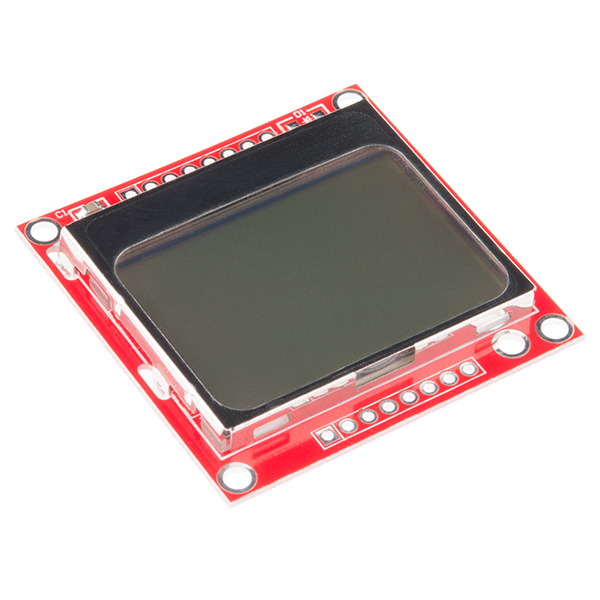
The Nokia 5110 is a basic graphic LCD screen for lots of applications. It was originally intended to be used as a cell phone screen. This one is mounted on an easy to solder PCB.
It uses the PCD8544 controller, which is the same used in the Nokia 3310 LCD. The PCD8544 is a low power CMOS LCD controller/driver, designed to drive a graphic display of 48 rows and 84 columns. All necessary functions for the display are provided in a single chip, including on-chip generation of LCD supply and bias voltages, resulting in a minimum of external components and low power consumption. The PCD8544 interfaces to microcontrollers through a serial bus interface.
Note: There may be small blemishes on these screens as they are surplus.
Note: Your screen may or may not have a diode on the PCB. It does not affect performance and will vary depending on our shipment.
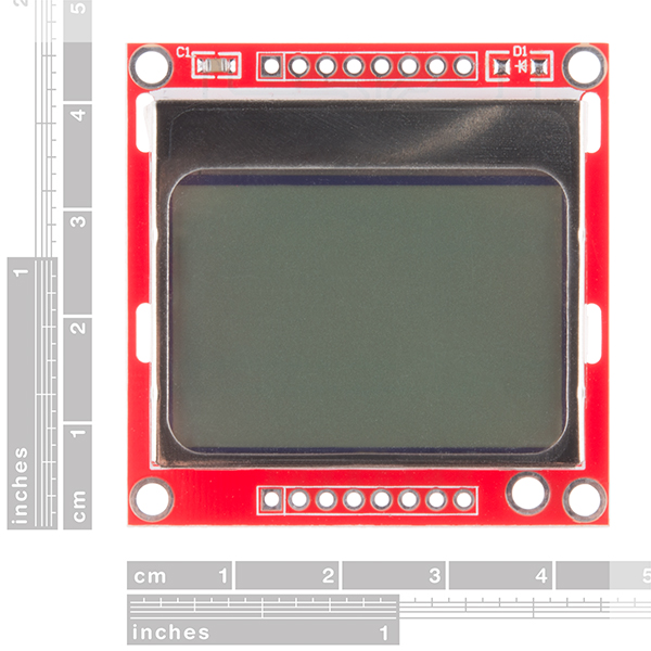
- 45x45mm
Graphic LCD 84x48 - Nokia 5110 Product Help and Resources
Graphic LCD Hookup Guide
November 18, 2013
How to add some flashy graphics to your project with a 84x48 monochrome graphic LCD.
Core Skill: Soldering
This skill defines how difficult the soldering is on a particular product. It might be a couple simple solder joints, or require special reflow tools.
Skill Level: Noob - Some basic soldering is required, but it is limited to a just a few pins, basic through-hole soldering, and couple (if any) polarized components. A basic soldering iron is all you should need.
See all skill levels
Core Skill: Programming
If a board needs code or communicates somehow, you're going to need to know how to program or interface with it. The programming skill is all about communication and code.
Skill Level: Rookie - You will need a better fundamental understand of what code is, and how it works. You will be using beginner-level software and development tools like Arduino. You will be dealing directly with code, but numerous examples and libraries are available. Sensors or shields will communicate with serial or TTL.
See all skill levels
Core Skill: Electrical Prototyping
If it requires power, you need to know how much, what all the pins do, and how to hook it up. You may need to reference datasheets, schematics, and know the ins and outs of electronics.
Skill Level: Competent - You will be required to reference a datasheet or schematic to know how to use a component. Your knowledge of a datasheet will only require basic features like power requirements, pinouts, or communications type. Also, you may need a power supply that?s greater than 12V or more than 1A worth of current.
See all skill levels
Comments
Looking for answers to technical questions?
We welcome your comments and suggestions below. However, if you are looking for solutions to technical questions please see our Technical Assistance page.
Customer Reviews
4 out of 5
Based on 18 ratings:
1 of 1 found this helpful:
Easiest to use small graphical lcd
It is a small graphical lcd with backlight on a sturdy pcb with probably one of the easiest to use controller ever at a ludicrously cheap price! what else could you want. if you are new to the joy of electronics and want to try coding for graphical screens this is the best starting point i can think of!
2 of 2 found this helpful:
Be Careful at 5V
We ran it at 5V and I think it might have blown our LCD. We were having trouble getting it to display anything, and when it finally did, it was very dim. Then eventually it displayed nothing at all.
Tried another LCD (same model), running at 3.3 this time, and it worked great!
So, be careful running it at 5 V.
Also, listen to the other members who recommended changing the contrast setting in initialization. You might need to play around with it, but you will get there eventually.
4 of 4 found this helpful:
Very good display, I've used several
There are a few things you need be aware of here.
Dirty connections: I have found that one of my units would randomly stop working or flicker, or alternate between being too dim or being too dark, and this was clearly a physical problem (pressing on the board made the problem change). The problem, as I discovered, was dirty contacts on the board and screen itself. I unclipped the board and found dust particles on the contacts. Cleaned both sets of contacts with cotton swabs and rubbing alcohol, and the problem was resolved.
Contrast setting: I think most of the difficulties people are having here stem from trying random hardcoded contrast settings. The proper way to do this is to allow for adjustable contrast settings by the end user. The acceptable range is between 0x80 (being a contrast value of 0) and 0xFF (being a contrast value of 127). The ideal contrast setting will change with ambient temperature. This is why I suggest making your contrast setting changeable on-the-fly, through your microcontroller software. Whether by a trimmer, or buttons, or whatever. For typical room temperature, a good value is likely to be around 0xBF. That's where mine is at. If it's too dark, decrease by increments of 1 until you find the ideal value, if too light increase by increments of 1. I have buttons on my device that do this and I save the user-selected contrast setting to EEPROM. The code for changing the contrast on the fly is easy. Set the SCE pin to low to enable the serial interface. Set the D/C pin to low (which tells the LCD you are sending commands, not pixel data), then send byte 0x21 which enables the extended instruction set, then send the contrast byte, then send byte 0x20 which returns to the basic instruction set. You do not need to reset the panel or anything like that.
Hardware SPI: use it. It makes the display so much more responsive. For this, connect the MOSI line to the microcontroller's MOSI pin, and the SCK line to the microcontroller's SCK pin. Then, avoid using the MISO and SS lines of the microcontroller unless you know what you're doing. On a ATMega328 chip, as found in Arduino UNO, Pro, and Pro mini, the MOSI and SCK lines are digital pins 11 and 13, respectively. Then you want your library to communicate with the LCD using SPI. Easy to do. The LCD's speed is 4Mhz, data is sent most significant bit first (MSBFIRST), the data clock is idle when low (Clock Polarity/CPOL = 0), and samples are taken on the rising/positive edge of clock pulses (Clock Phase/CPHA = 0). So for Arduino SPI, that means using SPI_MODE0. It's all downhill from there and you can chain multiple devices to SPI. It's wonderful.
I have a working library for this LCD that uses hardware SPI that I'm pretty happy with, and plan to release under MIT license on github sooner or later. If there is demand I can rush that process.
Definitely run this LCD on 3.3V. Don't even think of 5V. Not even a little bit. You should be able to put a voltage dropping resistor on the Vin pin, though, if you don't have a 3.3V regulated output.
1 of 1 found this helpful:
Surplus
I unfortunately was not as lucky as the other reviewers. The first screen I received was usable but defective (bad row). The great people at SparkFun send me a replacement no questions asked.
Unfortunately the second screen would not even turn on; The SparkFun Squad wanted to help me debug the issue, but I decided against it since it was pretty obvious that the screen was dead and I didn't want to spend time fiddling around with it. The one with the bad row will do just fine for now.
1 of 1 found this helpful:
TtgttGraphic LCD displays
I can get the backlight to work but nothing appears on the display itself. I don't know if I have the right library installed. I have checked my wiring several times and it appears to be wired correctly. Don't know what could be wrong, any suggestions would be helpful, thanks in advance. Graig
Be sure to check out the hook up guide -- https://learn.sparkfun.com/tutorials/graphic-lcd-hookup-guide
1 of 2 found this helpful:
Great LCD to learn how to use SPI.
Bought this display to learn how to use the SPI Bus on my Raspberry Pi 3b+. The display worked as advertised. No issues. The Sparkfun tutorial for the Nokia 5110 was very helpful.
I meant to give 5 stars (not 1) ... I can't edit the star rating :(
1 of 14 found this helpful:
Not used yet
The weather here has been so good that I've spent time working in the garden rather than working with electronic.
I might need a few more of these
This is a nice little screen. At first I couldn't get it to display anything, but after I re-read the instructions and changed the contrast to 60 everything became visible. This screen also works with the Adafruit and a few other PCD8544 LCD libraries, you just have to change the pins in the constructor (of the non-Sparkfun library) to match the pins in the LCD wiring diagram provided by Sparkfun.
P.S. Some libraries don't utilize the backlight. Just create a int for pin 9, set the pinMode to output, and analog write 0-255 to the pin to control the brightness of the backlight
Works as advertised. Thank's
Very Good
Works as expected!
LCD_Functions.h
I haven't found the header file indicated above. As soon as I can find this file so the sample program will run I will let you know how it goes. Thanks, Lewis
Nice
It's SPI (2 wire no SDO from LCD). Works well with Microchip PIC16F1454.
Simple, cheap and effective.
This does what it says it does for a cheaper price than many other lcd's. It is also very simple to use, so you can get started right away.
Nifty little display!
It is fairly simple to do either graphics or text on by simply using/modifying the example code. There is example code on-line to do a larger 7-segment display if you need bigger numbers. All-in-all very handy to apply to a project.
Easy to use display
Using it with hardware SPI and 3.3V. Had to play with some of the settings to get a good image. Can think of lots of cool projects to do with this little display.
I am current considering use of this display but have not ordered it yet. I am a little hesitant due to the number of users reporting problems with these displays. I am in the process of creating a PCB footprint for this display, but when applying the 3D model provided, the hole spacing of the display's connector pads do not appear to be on a 0.100" grid. Is this an error in the model or are the display's connector pins on a weird spacing? If so, what is the spacing? Any help would be much appreciated.
I would say use your best judgement. I have only looked at the reviews under the review page and they all seem fine; unfortunately, I don't have time to comb through all +200 comments. That being said, you can check out our Technical Assistance page linked in the banner above and our returns policy. Another resource for you is the [forum]https://forum.sparkfun.com/], where you can check for what issues users had and if there was a resolution to the issue.
As shown in the hookup guide the through hole header connections should be about a .1" spacing (image of connection into a normal breadboard). I've never used Blender and there person who made the models is no longer around to ask... so I can't speak to the accuracy of that file.
I had a project that needed some live data display, and looking for the cheapest low-power solution for our loggers lead me to the Nokia 5110 LCD. Once you get the backlight current under control, you can power the entire display from a digital pin, and if you use shiftout for soft SPI you can then get rid of the Reset and CS control lines. This brings the display down to any four wires you can spare on your build (incl. the power pin) and a ground line. This is much more manageable than what you see with the standard hookup guides if your mc is I/O limited like our pro-mini based loggers:
https://thecavepearlproject.org/2018/05/18/adding-the-nokia-5110-lcd-to-your-arduino-data-logger/
If you are looking for a tutorial on interfacing Arduino with Nokia 5110 LCD, then follow the below tutorial http://electronicshobbyists.com/interfacing-nokia-5110-lcd-with-arduino-nokia-5110-arduino-tutorial/
I got Conway's game of life running on this with only ~1k of RAM. was a really fun challenge.
I am trying to connect Nokia 5110 LCD to BeagleBone Black Rev-C over SPI protocol using Linux kernel's SPI driver.
I successfully installed and ran Adafruit's python-library: Adafruit_Nokia_LCD
I have a strange issue, when I run this python code first and then my C code, the code works perfect! But if I run my C code before the python code, I get no output. Logic says that the python code must be initializing something that I am missing in my code. Here's how I am initializing the LCD:
I am a novice in embedded programming. I would greatly appreciate any help. Thank you.
This LCD (I have the old-old kind) is absolutely my favorite. Yes, it has a board-to-glass connector that ranges from bad to abysmal, but it offers such a simple interface and so many pixels for so little money (obviously less if you buy only the panel.) Here are some clever things I've discovered:
Will fully operate on as little as 2.0V. That's power (Vdd) and i/o. It can be driven at 2MHz at these speeds; in fact, the LCD will work at even lower voltages but the contrast fades quickly and your microcontroller will likely approach its lower voltage limit too.
The initialization sequence is magic. Here it is, in case you were, like me, frustrated over and over again with varying sequences that others claimed to work but they didn't for you:
0x21, //switch to extended commands
0xE0, //set value of Vop (controls contrast) = 0x80 | 0x60 (arbitrary)
0x04, //set temperature coefficient
0x14, //set bias mode to 1:48.
0x20, //switch back to regular commands
0x0C, //enable normal display (dark on light), horizontal addressing
Reset/initialization can be picky - the datasheet says that the delay from power-up to reset mustn't exceed 30ms. What I found to be the best is to set SCE low and reset high at system bootup, wait 5ms for voltages to stabilize, lower reset, delay by ~1uS (1 nop @ 8MHz will do), raise reset then send it the initialization sequence above.
The LCD will work with the chip-select pin (SCE) tied to ground. This means that if it's the only device on the SPI bus, don't bother framing the i/o with a chip-select pin. If the bus is shared, frame the entire transaction, not every individual byte you send to the LCD. Interestingly, the display also seems to work fine with a floating Vdd pin - it must draw sufficient power just from i/o via clamping diodes; not surprising when you consider how low-power it is.
The Vout pin: Looks like you don't have to worry about it on this product, but the bare LCD will generate positive 6-9V on that pin. This wasn't totally clear to me from reading the datasheet.
Magic indeed! I'm using a different approach for the RST (pull low as soon as possible, hold low for 100ms, then set high and continue) just as a matter of making sure I get a clean boot, but otherwise I end up using your init sequence verbatim. Saved me a ton of work since I'd been fighting with it for two hours.
Kuy - good info... A few comments:
(1) I confirm this intialization sequence works, with the clarification noted in #2 below.
(2) The second command byte (the 0xE0 shown above) is not arbitrary. It is 0x80, or'ed together with a 7-bit Vop value. I found my display to be somewhat sensitive to this value. At Vop=0xBF, my unit was initializing electronically, but had a blank display (or solid-black, I can't remember now.) Anyway, I had to play with this value, and 0xB3 ended up working for me, so if you are initializing to this sequence and having trouble, try varying this parameter. The technical details of this parameter are explained in the datasheet, section 8.9, but really, you will just have to play with it.
(3) I didn't find reset/init to be all that tricky, but it's possibly because I'm powering the display unit from a port pin. That's right, it only draws somewhere around a mA or less, so I just use an output-configured port pin to run the display VDD. (This lets me turn off the display easily when I want to go into low-power Sleep mode on my micro.) So I let my micro do it's own reset sequence with all my port pins (including Display VDD, !Reset, and !SCE) at "0", and when I'm ready, I set, in sequence:
VDD = 1
!SCE = 1
!Reset = 1
These end up coming in a 1 us per instruction sequence (running a PIC 18F at 4 MHz.)
Note the datasheet says reset can be low when VDD is applied, and then has to be at least a 100ns "low" pulse. So powering up VDD, then applying !SCE at 1 us and !Reset at 2 us meets that spec just fine. I have had perfectly consistent startup operation with this sequence.
(4) !SCE tied to ground - yes, you could, but I've had fine results framing each byte with the !SCE signal - there's nothing wrong with that. Yes, framing a whole transaction is fine, too. Note the datasheet timing diagrams show that !SCE serves a reset function on the incoming serial shift register, so if you ever get a glitch in your serial transmission that gets the bit count off, respecting the !SCE timing (whether on byte- or transaction-basis) will automatically get the display controller's serial receiver synchronized back up on the next byte or transaction.
(5) If you are using a PIC to run ths thing, and using the PIC's USART or EUSART in a synchronous mode, be sure to note that the LCD controller expects the MSBit of each byte to be transmitted first on the serial line. The PIC 18F EUSART transmits the LSBit first. For now, I have lots of extra code space, so I've wasted a 256-byte section on a lookup table that reverses the bits in a byte. This way, I just write my initialization code normally, and I have a TransmitCommandByte() function that looks up every byte it sends so I don't have to think about that.
Once I get to a final version (or at whatever point I need to conserve code space) I'll just establish my final command sequencing, and hard-code in the bit-reversed values so I can get rid of that lookup table.
As a separate issue from the command bytes, all my graphic data are already created with the proper bit orientation, so I don't have to look them up to do the reversal.
Did you test that it's a 2V minimum? I was considering making this as a shield for a 1V8 AVR.
It may be possible to compensate for the low voltage by tweaking the contrast or updating slowly, but in my testing about three years ago journeys beneath 2.0V led to the display whiting slowly out like the face of an inexperienced fighter pilot in an aerobatic manoeuvre.
If you want a great low-voltage LCD consider a Sharp memory LCD. Pebble uses one.
Thank you! I'm not quite sure I do want an LCD yet, to be honest, I'm just considering the different options available. I'll check out the Sharp component, thanks!
Thanks for that sequence, worked perfectly! Advice for others: It took me quite a while to get this working on an ARM Cortex. Since there is no way to read from the LCD, it is very hard to know if SPI is working without doing everything perfectly. SO:
Use the contrast value that Kuy gives (0xE0) or darker - this will cause the display to be all-black so you can confirm it works. THEN you can adjust the value and focus on getting characters to write.
I ran into an issue with the "Example Code." I noticed that the screen was not properly displaying Hello World! [the output was "Hfmmp Wpsme!"]
The fix is to add a spacer [",{}"] to the ASCII setup code like this...
The correct fix is to delete the "\" (backslash) character in the comment for the 0x5C entry. The backslash is the "continue on next line" symbol, so the next line is not seen as part of the initializer, thus making everything following it offset by 1. Just change the "\" character to the word "backslash" and everything will be good:
Problems with my Display I just want to share my experience, maybe it can help others. I bought my display from eBay. A dirty cheap bargain from Hong Kong. I must say that it is exactly as the SFE breakout board, but of course, it didn't work. The problem I had was solid black display screen. No matter the combination of bias and contrast values that I set. The unit wasn't totally defective, because under a strong lamp light you could see the display trying to show the letters and pictures that are in the tutorial for Arduino that I got from SFE. Finally, after a long time of trials, I fixed it--> The problem: the bezel wasn't tight to the board, so the contacts of the display didn't work well. Conclusions: You get what you pay, don't expect well manufactured products and tested components comming from China at half the price you pay here. And second, it is totally no good idea to start up a new development with new technologies with untrusty material. Maybe you can try some cheap components after you are sure that you are used to certain technology (a display, a sensor, whatever), but don't try to break the barrier of new knowledge and tricky materials at the same time; because you won't be able to know who is the faulty.
Reozen, I am having this exact same problem. If I push down on the top of the screen, everything works. How did you end up fixing it? Did you have to take the display off of the board?
The problem with these displays, and it seems to be common to all the manufacturers, is that the PCB material is too thin. After a month or two, the board slowly bows away from the glass display panel under pressure from the conductive rubber connector strip. Pressing on the top centre of the metal part of the display makes it work again, but only temporarily.
If the LCD module is soldered to another board and the two top screws installed and tightened carefully to pull the bow out of the module it seems to prevent (or solve) the problem.
Mine all failed after a month or so when plugged into a proto board socket.
The only real fix for this display is to redesign the metal cover with a hold-down tag in the top centre, or make it with a thicker PCB that doesn't bow under pressure from the connector. Until that happens I won't be buying any more.
Oh my, that is indeed the case. Thanks for saving me hours of debugging!
As a side note, I would think that soldering the top row of holes to a board beneath would help with the issue. I have not yet tried this.
Could someone please post a "hello world" code for Pic 16Fxxx? (MPLAB)
The Arduino code works fine for me, but I can't make any thing work with Pic. I found this code at http://www.sunbizhosting.com/~spiral/ , but can't figure out what I'm doing wrong.
I used port C on my 18F for the outputs to the Nokia lcd...
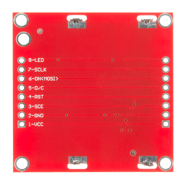
// Matches Sparkfun Pinouts
#define nok_cs PIN_C0 // 3-SCE
#define nok_res PIN_C1 // 4-RST
#define nok_dc PIN_C2 // 5-D/C
#define nok_sda PIN_C3 // 6-DN(MOSI)
#define nok_sclk PIN_C4 // 7-SCLK
#define bk_sel PIN_C5 // 8-LED
C code...
(your PIC specific includes)
#include "nokia5110Driver.h" // download from post below
void main(void)
{
nokia_init(); // initialize nokia lcd
nokia_gotoxy(8,0); // position in x, y
printf(nokia_printchar," Hello World "); //refer to the nokia driver include for formatting
}
I would be interested in your library if you can share again. You can contact me through nygma.hu.
Got it working using the 5V straight from the Arduino. Also used the 'Example Code' cited above, but modified the pin assignments to fit my setup.
You can check out my setup here.
Noticed any adverse effects running it like that yet?
None so far, but dont have a whole lot of run-time in this setup
Hello.
I am having problems to get this LCD working with Arduino
(I'm just a newbie)
I'm trying it with the first Arduino example, linked above, using the initialization sequence pointed by Kuy and Member197735 (thanks to both).
I have readed carefully all the comments, and recomendations. But I should be missing something.
I'm using voltage dividers to supply 3V in the inputs of the LCD, because of the Arduino works in 5V. LCD Vcc and LED are powered from the 3.3V output of the Arduino. The LCD only displayed something when I used: R1=470K,R2=820K. I have tried several values to obtain 3V, but the LCD showed nothing. I don't understand that.
This is my circuit and this and this is what the LCD is showing.
Any help would be very appreciated.
Thanks!
I answer my self:
I powered this PCB from the 5V line of Arduino, and used 5V logic, directly from the Arduino's digital lines, without voltage dividers.
It worked very well, including the Arduino example linked above.
I also used a 270-Ohm resistor to limit the current in the backlight leds.
This is a very nice and cheap display!
Why is the diode missing in the working example?
You know, thats a good question. I never even spotted that the diode was missing.
If you wanna make the first (simple) example code at http://www.arduino.cc/playground/Code/PCD8544 work you should add (in void LcdInitialise(void))
LcdWrite( LCD_CMD, 0x21 ); // LCD Extended Commands.
LcdWrite( LCD_CMD, 0xBf ); // Set LCD Vop (Contrast). //B1
LcdWrite( LCD_CMD, 0x04 ); // Set Temp coefficent. //0x04
LcdWrite( LCD_CMD, 0x14 ); // LCD bias mode 1:48. //0x13
LcdWrite( LCD_CMD, 0x0C ); // LCD in normal mode. 0x0d for inverse
(taken from the second code example) and also in the beginning of your code:
define LCD_CMD 0
You'll want to put a command byte of 0x20 in there, after the 0x14, and before the 0x0C. This is needed to put the display back into its "basic" command set, so it will correctly recognize the 0x0C command byte that puts it into "normal" (not inverse) display mode.
On the page it says there is a 3D model for this part, but i can't find it in the repo
I'm interfacing this LCD with ATMEGA 32. Its been more than a week that I've been trying to get it right. All I get is the LED dimming effect. Here is my initialization code..
Has anyone played around with minimum and maximum SPI clock rates with this display? I know the datasheet says up to 4 Mbit/s, but assuming this display is the only thing on the particular SPI bus, what's a good minimum clock rate before you might start to notice delay in the display refresh? I mean TVs are 60 Hz - 120Hz.
I have a similar board made by mib-instruments and bought from ebay years ago. It has been my standard spi test tool because it's so easy to work with. http://www.ebay.com/itm/Nokia-5110-LCD-84x84-dot-martix-backlight-PCB-RED-/320684678723 (specs http://i1119.photobucket.com/albums/k636/mib_instruments/diy/LCDC2A0SPEC.jpg)
I wanted another one so i bought the sparkfun item but it doesn't quite work: it flickers and blackens occasionally but my graphic never shows up. Is there a bulletproof arduino sketch I could use to test it?
I almost have it working satisfactorily but I find that the bottom 1/5th of the screen does not function correctly. Sometimes it has some random blocks that are black, most of the time it is blank. I am not sure what would cause this. Is it safe to assume it is a defect on this module? I also noticed sometimes it randomly cuts off vertical segments of letters (but not every time!) I believe the letters would be written vertically in the examples. Is it possible that the arduino is sending commands too quickly?
These LCD's need cleaning. I have an average failure rate of about 15-20% on delivery. The most common problem is that the contrast is too high, and there's constant flickering / changing of contrast compared to the other 80% of them.
The solution is fairly simple, unclip the LCD from it's board and clean the pads on the PCB with 99% IPA. Then remove the lcd back plate and contact bar. Sometimes the contact bar is stuck fairly well to the glass, peel off carefully. Clean the contacts on the LCD glass with IPA, if any residue from the contacts is left on, rub it off carefully with IPA / tissue.
Clean the contact bar with IPA both sides.
Reassemble, making sure you don't have even the smallest spec of dust on the bar or contacts. The slightest spec will cause the bar to raise slightly, and that and adjacent contacts to not make contact, or be intermittent.
I think the root issue is non-clean assembly, flux on the pads and dust.
Given that these units are previously loved displays, probably general muck / grime doesn't help either.
Also gold contacts on the PCB instead of tinned would help with contact.
India Pale Ale seems like an odd cleaning solution for electronics :)
Hey, it's great you did a 3D model of this display, but how about an Eagle entry in the library so we can use it there too?
I love this little display! I wanted to be able to create images for it but nothing I saw did exactly what I wanted. So I wrote a processing sketch that creates 84x48 squares on the screen and allows you to click to turn them on or off. Also has buttons to invert, move up/down/left/right, and flip horizontally/vertically. Then, it saves the hex data to a text file to copy to your code. You can also load an image (any size, any colors) and it will scale it, convert to b/w, then put it in the rest of the program so that you can alter the pixels or move it. It isn't perfect for every occasion but I've found it useful and I hope others might too. It is heavily commented so it should be easy to figure things out and change them if you want something different. http://thewanderingengineer.com/2014/07/12/nokia-5110-screen-photo-to-bitmap-converter/
I've got 3 of these and wired them up as suggested in the hookup guide and downloaded the example code, and the only thing that seems to work is brightening and dimming the LED. I've started again from scratch at least twice, tried all 3 units, and verified all the connections match the hookup guide, and I still the ssame result; no graphics, no text, just a border. Any ideas as to what might be wrong?
Never mind, I had no problem running it at 5V directly from the Arduino with the contrast value bumped up to 45 or above. With 10K ohm resistors on the control lines as shown in the sample hookup, I get a blank screen. Also removing the backslash from the sample code got garbage characters, so I left it in.
Possibly the Arduino software now handles the "\" in a comment better than before :)
Anyone taken these things apart yet? You know the flexible rectangular blocky thing that connects the contact pad on the board to the LCD itself? What are these called?
You're looking for "zebra connector".
Possibly also of interest: Z-Axis Conductive Tape
Thank you!
Got mine running last night and found two problems with the code, one of which was the backslash a couple of others have already noted. Second was that the LCDCharacter() writes two blank vertical lines, one before the character and a second after, when only one is needed. Without the extra blank you get at least one additional character on each line. I'll probably also move the ASCII font table to PROGMEM space to save on RAM and then start to work on some big digits for a clock.
I'm using this LCD for a large Arduino UNO project, but I'm running out of SRAM memory space. I was wondering if I used PROGMEM on the LCD ASCII array if that would help. If so, does anyone know what the right code for this would be? After looking through a lot of PROGMEM examples, I'm not advance enough to really grasp everything that's going on. Any help you can give would be a great help. Thanks in advance!
I used one of these LCDs with an Arduino to display GPS information. I wrote a few functions that can display large numbers (28 px high) if anyone is interested, this lets me display speed, heading etc. A writeup of my project is here: http://mechinations.wordpress.com/2014/04/07/gps-sailing/
These are great displays. I ran into a problem using them with the nRF24L01+ radio transciever, which requires the use of the SPI bus. If one attaches both the radio and the display MOSI and SCK pins to pins 13 and 11 as instructed in the hookup guide, the SPI traffic of the other device (in this case the nRF24L01+ radio) will prevent the display from functioning. The easy solution is to move the Nokia 5110 MOSI and SCK pins to any other digital pin. This should be made clear in the hookup guide, where it says there is no choice but to use the hardware SPI pins for the display. I found out that is not true at all. I hope his helps others with the same problem. Despite the occasional bad display these carry much more information that the comparably prices 16 x 2 LCD and use fewer pins too boot. What a deal!
I was able to get this work only after using 5v, and lowering the contrast by int from 55 to 45 to remove the "black box" flickering behind the screen drawings. When I power with 3.3v, nothing - just the LED and dimming etc of the screen. I'd love to use 3.3v (and it seems based on responses here) that it should run only on 3.3v. Any ideas anyone?
It should run on 3.3V only, I found it very sensitive to the contrast value. 55 works for me, but 45 makes nothing show up. You might need to play with this value.
I was wondering if anyone had happened to convert this demo file to a library for easy use? I would love to do it myself but unfortunately I am not very good at it.
The LCD works great, but i cannot open the c4d file you provide at your github repo
Does anyone know if you can remove the LCD from its housing and do things like flip or remove the polarizer?
Hello people, is there anyone that can tell me the height of this display. I mean the displays height 45x45 mm is the size but i wonder the thickness of it. Only the display not the pcb. I couldn't find this info on the datasheet. Best Regards..
We have the sketchup file for this part in our 3D Models repository. That will give you all of the part's dimensions.
This is a great display for the money, certainly the best bang for the buck of you can live with B&W and lower res graphics. I have a lcd driver for Arduino I will post on http://www.marchdvd.com/5110 so take a look there it draws text aligned on pixels boundaries of 8 and draws lines and has invert video options.
The example code does not seem to allow me to use bitmap arrays smaller than 84x48! Does anyone know of a solution to do this?
I just started messing around with this LCD using a STM32F103 microcontroller running at 72MHz... it works great. The only problem I had, and I suspect others might have if they are using fast processors, is that you have to deliberately introduce the setup and hold time delays on the DC pin... if you don't you will get spurious pixels written to the display. I used a delay of 10uS, although the spec says 100nS is fine.
Anyway, just hope to save anyone else a little trouble...
Hey guys, i keep getting errors with the Example Code: 'PCD8544' does not name a type
It highlights this line: PCD8544 nokia = PCD8544(3,4,5,7,6);
I have connected the libraries properly. Can someone tell me how i can make the expample code work again?
No schematic or Eagle files?
We didn't design or assemble this, so unfortunately, we have posted all of the files that we have available from the manufacturer above. I can get a request for a 3D model in for you if you would like though!
Hi Toni
Did you request a 3D model, I would really appreciate that
Yup, the request is in there! Hopefully we'll get it posted soon.
Hi Toni
That sounds good, do you hvae any ETA on that. I could really use that model...
Hopefully in the next few days it should be up. Our designers who do the 3D models are pretty slammed with the holidays coming up so it may take a few days.
It took less time than I thought! You can find the model here.
Would it be possible for you to provide the details of the designer who designed this PCB. I would like to have Eagle design to modify some features.
Thanks
I'll contact our supplier and see if they can get us the files.
Mine has a 5th mounting hole near 8-LED on the silkscreen that I don't see in any pictures
Hey guys, if you are interested I managed to run this LCD on a Raspberry Pi :D Nokia 5110 Raspberry Pi
Awesome! Thank you for sharing that with us! Edit: I actually just added this to our GitHub collection, so you could issue a pull request there if you would like to share it on GitHub as well.
Just a heads up to anyone trying to run the Arduino example. Make sure you plug Vcc into the 3.3V output on the arduino board. I also had to change the line
" LcdWrite(LCD_C, 0x14 ); // LCD bias mode 1:48. //0x13 "
to
" LcdWrite(LCD_C, 0x12 ); // LCD bias mode 1:48. //0x13 "
Otherwise the screen was completely dark and unreadable.
Great lcd! The only problem I have is the lcd sometimes displays lines of grayscale pixels down the screen when the pixels are unevenly lit
Will I be needing a logic level converter to run on a 5v Arduino?
I been trying to display 8-10 images as an animation. The individual images all work, but when I trey more than 8 images, nothing happens on the screen, and above 2 images, I get errors in the drawing of the images. Is there some kind of buffer or violent reset I can do so that the data doesnt get jumbled up?
same im facing any solution found???
Can someone help me edit the code in the arduino example to display readings from a sensor, I've looked through all of the links and searched through the Internet but I couldn't find an example anywhere, it would really help me if someone could tell me how to do this.
Has someone already been able to get this display to work with an Arduino Due? For some reason I cannot get it to work while it does work perfectly on my Mega. Any ideas why it may not work?
Added a driver for this display to the object-oriented arduino platform; Cosa. Please find example code at https://github.com/mikaelpatel/Cosa/blob/master/examples/Drivers/CosaPCD8544/CosaPCD8544.ino and source code at https://github.com/mikaelpatel/Cosa/blob/master/Cosa/IOStream/Driver/PCD8544.hh.
This driver supports iostream output with form feed, new line and backspace. It also supports drawing of icons and histogram bars. See the example code.
Have fun.
I just spent the last couple hours struggling with this LCD because of something very stupid of me. I was using an atmega328p in AVR-GCC and using hardware SPI. Thinking i didn't need MISO I hooked it to DC. The LCD worked absolutely fine until I tried to set the x and y position in the ram. It started acting weird every time I tried it. Finally I put dc to another pin and BAM NO PROBLEMS. Looking back I feel pretty stupid but hopefully this post will save someone else the same mistake. Other than that great LCD for my projects
I made up a short tutorial on how to drive the display with the 5V arduino using a voltage divider - use on your own risk: http://arduinoandsoftware.wordpress.com/2012/12/30/nokia-33105110-3-3v-display-with-5v-arduino/
Is there any data on power consumption? I need to estimate the power consumption when running everything on 3 V.
My screen was bought from Microcenter on 10/14/2012. It works via the example. Said screen was the retail packaging variety.
How would i tell the lcd to start on a new line? would i say lcdstringln?
I need to know where to drill the mounting holes in a board I'm designing, can someone get more precise measurements of the physical dimensions of this board?
I used the ASCII font given in the example code in one of my projects and ran across a mystifying bug. I was developing code on a PIC12F675 to drive an OLED through its SPI interface. (Yes there are enough pins and memory to do this!) I was using the HI_TECH C compiler and tried several different approaches and never could get the "]" character to display. After pulling what is left of my hair out for 2 days, I realized there was a "\" in the comment for the previous line of the ASCII font definition which caused the compiler to treat the array entry for ] as a comment! Just replace the "// 5c \" comment with "//5c backslash" and everything works! I don't know if this effect is peculiar to the HI-TECH compiler only.
Member #341079 I have the EXACT same problem with the display...the misterious fade to black... Anyone have found a fix for it yet?
C ya
The Energia folks have an example program for this LCD and the TI Launchpad written using their Arduino style tooling. I've updated their example and added the ability to report back the temperature over a UART. It is a very simple hardware setup since both systems are 3.3v. http://joe.blog.freemansoft.com/2012/08/digital-thermometer-with-ti-lanchpad.html
P.S.
I can't get the Example Code on this page to compile either...
The errors are:-
Adafruit_PCD8544.cpp: In member function 'void Adafruit_PCD8544::begin(uint8_t)': Adafruit_PCD8544.cpp:155: error: 'digitalPinToPort' was not declared in this scope Adafruit_PCD8544.cpp:155: error: 'portOutputRegister' was not declared in this scope Adafruit_PCD8544.cpp:156: error: 'digitalPinToBitMask' was not declared in this scope
Surely "Example Code" should run straight out of the box?
Having Problems...
Despite my earlier post, I'm now having problems with these didplays as I come to try and actually use them.
I'm running with an Arduino Uno R3 and using voltage dividers on the signal lines for the hardware setup.
1) There seems to be a serious issue related to contrast and/or connections between the display and the breakout board. When running "Black on White" text, the background gradually darkens to a black rectangle covering the etire display area but will revert to normal if the centre of the metal surround is squeezed towards the pcb, however, putting a sprig clip on it to keep it comoressed doesn't seem to cure the problem, but just slows the raste at which it fails - waggle it and it comes good again.
2) I'm really struggling to find unformation on using this display with the Arduino. The example (pcdtest.pde) provided with the Adafruit libraries (Adafruit_PCD8544 and Adafruit_GFX) won't even compile and the only library I have found that I can make any sense of using is the PCD8544 library from Google (http://code.google.com/p/pcd8544/downloads/detail?name=PCD8544-1.4.zip) and I can't really uderstand how to do graphics with that.
I did find another example (did't save it and can't find it again) that worked with the Adafruit libraries as it was supplied (including graphics), but trying to change it in any way beyond changing the text of the "Hello World !" string (which actually shoed on screen as "Hffmmp Wpsme !", so obviously a coding problem there!!!) just locked everythig up.
I tried using the "LCDAssistant" package to create a logo from a graphic that I resized to a b&w jpg of 84x48 but every byte generated was 0x00 so that was not right. I tried fiddling with the settings (flying blind) but still got nowhere - does anybody know the settings for LCDAssistant and this display and has used it successfully?
Maybe some of the answers are on here somewhere but, frankly, I don't understand a lot of what is being said - I'm a very old dog, who is struggling badly with new tricks...
Any help or advice appreciated, thanks.
Hi - for some reason (way above my "new to s/w" head) the code hates the \ character, even in comments. If you take out the backslash in the character definition section it works. My tweak is:
... ,{0x00, 0x7f, 0x41, 0x41, 0x00} // 5b [ ,{0x02, 0x04, 0x08, 0x10, 0x20} // 5c backslash - presence of backslash even in comments invalidated next row of characters ,{0x00, 0x41, 0x41, 0x7f, 0x00} // 5d ]
...
For what it is worth, I was using Arduino v1.0.4 .
I have purchased a couple of these from Proto-Pic in the UK to build an Arduino-based test device for use in my workshop.
One of the things that I test regularly is a commercial item that features a 16x4 (HD44780) display. Currently I have a 20x4 on a flying lead that I plug in to determine if a display failure is down the lcd display or the main board.
Is there any way to get the 5110 Graphic Display to work with signals that were feeding to an HD44780? - if I could build that in then I would have a complete multi-testing set up in one box.
I'm very out of date hadrware-wise (I was out of electronics for 30 years) and I'm not a programmerby any stretch of the imagiation (even a relatively simple sketch takes hours eliminating the errors one by one).
I have the other test functions working ok by using the library and cobbling together code from projects I've found on the web (very inefficent coding when put together I'm sure, but it works) but I'd dearly love to add this extra functionality.
Can anybody help?
Thanks
Duncan
I am using arduino example and while i am getting proper images and text i also get some odd horizontal flickering. It looks like several horizantal lines across the screen on the background with image/text on foreground. I tried switching to only use digital pins on my arduino leonardo but i still see this behaviour. Any ideas?
Make sure your power is regulated correctly, and that all of your soldering points and connections are good. It may simply be a bad screen. If you still run into problems, shoot us an email at techsupport@sparkfun.com
Hello! This LCD was able to be operated on this weekend. The Datasheet, the Arduino Example, the Quickstart Guide and the Example Code were very useful. I wish to express my gratitude to you of the author of the article. Thank you!
http://blog.livedoor.jp/miyanobspage/archives/2426895.html BATTERY:UM-3 (LR-6) CPU:ATtiny45 8MHz(INT RC OSC)
I have found the eagle library! Go here:
--> http://cadsoft.de/downloads/file/lph-7366.lbr
Is there mechanical documentation for this (location of mounting holes, location of screen relative to board, etc)? Yes, I can measure it but I'm lazy...
unfortunately, we don't, sorry!
would this work with the pro mini
would this work with the pro mini
It works quite easily (if you pay attention to the voltage advice).
I only had a little problem showing lower case chars when using the example code but it seemed to be a problem with the comment "// 5c \". Once the backslash was removed everything was working as expected. Great display, I think I'm going to get a bunch of these.
Thats a really good catch. The text editor doesn't catch it, so I wonder what the issue is. It must be some sort of continue to next line character.I would have spent all night trying to figure it out. Thanks
Is it possible to display text on this? If so, how?
Thanks.
at adafruit they say that you need a level shifter that they include. Im confused it seems like no one here is using one. whats the deal?
EDITED FOR FAIL: The LLC on this site won't work
Here is one way to control the 5110 LCD display with a Launchpad.
I see that this item is Out of Stock (back-order allowed). I have a embedded system I have been documenting / publishing the design for over the last month, so I would like to know if Sparkfun Plans on keeping this part and if so for how long? Is there a part you would recommend for replacement if this one is going away?
Thanks!
we have every intention of keeping this item, it's just taking a little longer than usual to restock it. There isn't an ETA right now though, sorry!
What is the usable display size for this screen? (Dimensions were there are pixels.)
LadyAda has a nice write-up on how to use this here; http://ladyada.net/products/nokia5110/
It's roughly the same price on both sites.
BTW; I'm not advertising; i'm just trying to help out- it helped me!
Might I suggest you (SFE) source some of the Electronic Assembly's LCD Dog-S series. I think they would be a step up from these at a reduced price. I don't think that they website is up to date, but their part number is LED39x41-GR.
edit: Correction, that is the part number for the backlight module. The LCD is DOGS102W-6.
I recently completed a port of the Arduino GLCD library for the PCD8544 using one of these displays. You can find it here:
git@github.com:MikeSmith/glcd_pcd8544.git
In conjunction with M2TK this gets you a fairly respectable graphics library and a forms-based menu system on your tiny device. Woot!
Mike,
the url you provided doesn't work in a browser, but this one does: https://github.com/MikeSmith/glcd_pcd8544
This is really nice. But it's in CPP. I use the gcc (win-avr) compiler. Do you have a link to a C library like this? Otherwise I'll have to try to port this to C. Which would be a real task because I have no experience with CPP.
I just got 2 of these. Haven't had a chance to hook them up yet. But I gather that the LEDs are green. Has anyone managed to lift up the display and change the LEDs for white or other color?
What does the VOUT pin do?
Where are you seeing a Vout pin?
I made a little font generator for the Nokia 5110 in the processing programming language (processing.org). It allows you to convert any font and any character that you can display on the screen into a list of hex codes that can be directly used in an embedded system (I'm using msp430). Just type a character and the corresponding hex codes will be in your clipboard and you can copy them into your program. It starts with an example with the chinese character for 5. It should work on any system that can run processing (e.g. mac osx).
https://sites.google.com/site/arduinowatch/Home/FontGenerator2.pde?attredirects=0&d=1
all the nokia 5110 lcd i recieved, i have noticed that the RED PCB is a bit bended.
I have 6 of them. I have only test 2 of those and they work fine.
I dont know why they are noticeably bended.
I am guessing that you are seeing the PCB bent away from the back of the display, up near the "top" of the display region, when it is viewed in normal operation, right?
This is because this is where the connections are on the back of the "display glass". These connections are carried down into the PCB via a small strip of that elastomeric connector material. This material works by being compressed between the two substrates (the glass and the PCB) to hold it in place and make the connections between the pads on each surface. As a result of being compressed, it puts a force "up" on the glass, and "down" onto the PCB. In this particular design, this has the result of bowing the PCB in the units I have purchased.
My thought, if I were up to me, would be to redesign the metal hold-down bracket, to have one more metal tab going down through an additional slot in the PCB, right there at the center of the top edge of the hold-down bracket. This would carry the majority of the reaction to the force exerted by the elastomeric strip, and should minimize board bowing.
I finally got around to running this LCD on my 3310 PCB. It is working fine with one minor problem. The SF 3310 display hides to first line of bytes for some reason and I had to offset everything to compensate. The 5110 doesn't do this as behaves as expected. I haven't heard anyone else report this so maybe my initialization code is different.
My fix.
ifdef lcd3310
endif
ifdef lcd5110
endif
I found the LCD bias value must be set to 0x15 to get good constrast consistently.
Using a 3V source, my LCD often worked OK using bias 0x14 like the other examples, but sometimes it would appear gray and faded. The fading would lessen if I touched the panel lightly with my hand for a few seconds, then let go, so maybe it's a temperature-dependent thing?
After writing a program to let me interactively adjust Vop, temperature coefficient, and bias, and experimenting with different values, I found that bias 0x15 worked much, much better than 0x14. I'm also using Vop 0xD0 and temperature coeff 0x04, but those don't seem to matter as much.
I also noticed an error that's repeated in many of the examples:
0x14, //set bias mode to 1:48.
0x14 is not 1:48 bias. If you read the datasheet on the top of page 16, 0x14 corresponds to a bias of 1:40/1:34. If you want 1:48 bias as the comment says, use 0x13. The 0x15 value I'm using corresponds to 1:24 bias.
Ack! After two days of working nicely with 0x15 bias, I reset the board today, and the LCD appeared way over-dark. I changed the bias back to 0x14 and it looks perfect. What the heck?! I think there must be some temperature-sensing or temperature-dependence going on, so the same init values may produce good-looking results one day but not the next.
If you are having problems with the black pixels in images/warping PCB, use original Nokia 5110, I happened to have one at home and it works as it should, no bad connections degrading image quality.
Does anyone know whether this can be stripped of its backing so it can be used in transmission? I would love to use this as a modulator for a laser beam. Or if someone knows a similarly cheap transmission LCD that would be fine too.
Has anyone created an eagle footprint for this? I'll be doing so when the order arrives. Basically just the outline with mounting holes and the 8 pin header.
Edit
Cadsoft eagle library for Nokia 5110 - Nokia 5110 Eagle lbr
Modified C Driver for Microchip PIC 16, 18 series with backlight control (for Sparkfun pinouts) - Nokia 5110 PIC C Driver
Somebody should permanently host these files, any takers?
Hi! Could you please upload again the Drivers? The link is not working anymore! thanks!
Hey, can you repost your Eagle LBR? the link you posted as expired.
This lcd is so easy to use!
For those of the arduino persuasion, I wrapped some simple methods up in a library based on this arduino page http://www.arduino.cc/playground/Code/PCD8544.
This is my first library for arduino but I hope it's useful to someone. Check it out here:
http://unicycle.drupalgardens.com/content/speedometer-hello-world
Stuck. Blank LCD. Added 0x20, changed Vop to 0xB3. Guessing connections may be the issue? 3.3v for LED and VCC. GND to GND. Remainder connected to Arduino via voltage dividers. What am I doing wrong?
This is a great little lcd. When I first wired it up, the backlight was shorted (accidentally) against my 5v rail, so i got some magic smoke, and burnt to LEDs but it re-soldered the offending joints and it works very well now. Something to note: the refresh and write times are much, much slower if you use 5 volt logic. I stuck in a logic level converter and it ran at least 5x faster.
I did the same thing (see my comment above), but I still can't seem to get anything to display. 3 of the 4 backlight LEDs still light up when I give them power, but I'm wondering what joints you re-soldered to get it to work again.
Also, I'm assuming it's okay that there's no diode on my board like there is shown in the product image. I guess other people's boards are coming like that, too?
A couple things:
first off, the best contrast setting for the unit I received was B3. This can be done like this:
LcdWrite( LCD_CMD, 0xB3 );
You can also use FastLCD to convert your bitmaps - google it. It outputs BASIC code, but you just search and replace &h to 0x and you're grand. It has the added advantage of being an editor for touching up output.
I found that same 0xB3 value works just right for the two units I have. I wonder if some of the difficulties people have getting them going is from using "E0" or "BF" or some of the other values I've seen posted. When I first powered mine up, I got NOTHING on the screen, and I would have thought it was dead, or assumed mine had "bad connections", if I hadn't known to play with that Vop value...
I recently obtained a virtually identical LCD from a Nokia 5160, and although its backlight LEDs are green, not white and conversely use different voltages, I had success hooking up the LEDs' Vcc pin to a PWM capable pin on the microcontroller, allowing me to control backlight intensity (I didn't need a current limiting resistor for this either, but adding one will help reduce current drain on the controller).
Seems like the PCD8544 library does it's own SPI bit managing and it really doesn't like me using the SD library (also talks SPI) at the same time. I've made sure I've got all the SPI pins matching for both libraries (MISO, MOSI, Clock are the same and each device has it's own Select), but it looks like the SD.begin() call just breaks the SPI bus for the 5110 and it becomes non-responsive. The LCD works just fine if I don't initialize the SD library and the SD card works fine if I do initialize the SD card.
Anyone have any experience using this LCD with another SPI device? How did you keep everything happy?
Thanks!
I'm pretty sure I tracked down the problem- the PCD8544 library uses software SPI while the SD library uses hardware SPI and I'm pretty sure the Arduino can't do both over the same SPI clock/miso/mosi pins. Anyone know if this LCD will work with hardware SPI?
The answer was yes. Ended up being a small change to the PCD8544 library and now it works great!
Hi! I'm having the same problem. Could you please let me know what was the small change you have done to the PCD8544 library?
Hi! I'm having the same problem that you explained a lot of time ago, maybe you've forgotten it but, what where the changes you made to the PCD8544 library?
I'm using an Arduino nano 328p, I have the LCD connected to pins 7,6,5,4,3 and the SD to MOSI - pin 11 MISO - pin 12 CLK - pin 13 CS - pin 10
I set the LCD library like this: LCD5110 myGLCD(7,6,5,4,3);
Hope you remember smthing! thanks a lot!!
I accidentally (well, intentionally, but stupidly) plugged the LED backlight line directly into 5V when I first got this, and I saw (and smelled) the magic black smoke escape. I believe the black smoke only came from one of the backlight LEDs burning out, because I only notice one of them not working now. The other backlight LEDs still light up okay, but I also now seem to be having trouble getting the display to show anything. I'm just wondering if I could have messed anything else up. It seems like others have had their issues with this display, so I was hoping I maybe had something misconfigured. I'm fairly certain I have the pins assigned properly, but maybe I'll tinker with the contrast. Any recommendations for setting the contrast value?
I'm using a Teensy 1.0 as a Teensyduino, and everything runs at 5V logic.
Any ideas, tips, recommendations?
I've had issues with the LCD not showing anything intermittently. You got to make sure that all the connections are secure, and for the reset pulse, be sure to have a delay that's 30-50 milliseconds long.
The code is unportable for the MSP430 using C. :/
The code is portable!
I forgot to include one of the most important commands:
Const
Awesome. So does that mean that the code can (largely?) be copy-pasted into an MSP430 IDE and executed?
If you've got some example code for it, I'd love to see it! I've got plenty of MSP430s lying unused.
I'll post it
I've got some LCD code for the MSP430.
http://pastebin.com/KtZazFvG (C file)
http://pastebin.com/vmv7TY31 (H file)
i try example for arduino... i change pin... but it not worked...
Who ever started this screen? can you publish simple worked example?
Anyone have any example code for PicAxe please? Thanks much! Andrew
I'm working on that.
As much as I love SFE products and will continue to order from them, this is one product I would not recommend. The connection between the LCD unit itself and the carrier board is via those rubber polymer connectors. All the planets must line up properly for them to work. In this case, the carrier board was warped preventing the connection from working. You will find other such remarks in the comments area.
I wish I could have gotten this to work because it was the perfect match to my needs (other than that it had to work!).
I have purchased 3 of these in recent past. One of them would power up but not display. They are a great size for what I want to use them for.
Out of curiosity - what indication is it giving you that it is powering up, if there is nothing on the display? There are no outputs brought out from the controller, so what feedback are you seeing that leads you to believe it is powering up?
I was referring to the backlight. I have used several of these for wireless devices and noticed the quality seems to degrade overtime.
I've followed the linked-to Arduino example and I get nothing on the display. Should it just work without any other components? The link mentions a possible cap on VOUT but there's no such pin. Googling has suggested my Duemilanove's digital pins will be @5V but I need 3.3V?
I have connected LCD:Arduino as
VCC:3V3
GND:GND
SCE:7
RST:6
D/C:5
DN(MOSI):4 is this "SDIN"??
SCLK:3
any help would be appreciated, thanks!
Well I tried cluening's voltage divider and still nothing so I suspect, like Skye, I have a dud. The board is a little warped
:-(
1) don't give up
2) read every posting
3) follow every link
4) try every suggestion
I have mine working now! The secret was oz-solutions's linked-to observation about the second code example which does more initialisation. I suspect that the default contrast etc makes the screen blank.
Is there a way to control contrast?
My display shows all dark, with the text darker... Not quite optimal.
yes you can set the contrast, see p14 of the datasheet, the "Set Vop" cmd seems to control contrast
Are there available pcb dimensions? At least pitch between holes and pcb connection..... Thanks.
The board is 45x45mm
The dimensions are in the images!
And the pitch is standard breadboard pitch.
I bought one of these that has the problem where you have to squeeze the top to make it work. Is there any way to fix it? If I take off the aluminium bezel am I in for a hard time?
Would you guys offer bare PCB? Or .brd file.
Thank You
No, sorry. We don't make these so we don't have access to those files.
You don't make the PCB? I thought you make all of breakout boards here.
Not EVERY single one. It looks like one of ours, but it isn't. It's just a coincidence that it's red. But we buy this one outright.
Where do you buy this from? Could you please give their details? Thanks !
Has anyone controlled this LCD via a Picaxe processor?
I'm currently trying to port the Arduino code to PICAXE 20X2.
After working out a messy voltage divider for all of the inputs to this guy, I figured I would share a drawing of my breadboard for anybody else who wanted a pre-done example of how to set it up:
nokia5110_bb.png
I'm sure there are better ways to do it, but this one is working for me right now.
Don't do this. Each divider will be burning 20x the entire amount of current that the display needs to function, and the whole assembly will waste 100x the LCD's needed power and many, many times more than even the atmega needs to run at full speed. This will kill battery life.
Either use higher resistor values, n-mosfets for level conversion (see this Sparkfun BOB for an example), or drive the whole system on 2.0V - 3.3V (don't know how easy that is with an Arduino.)
I got this little screen for my Netduino but it just won't work! I've tried everything, and even worked on it with someone who had the same screen but it won't work. We got it all right, but it just won't work. If anyone here gets it to work with the netduino please let me know.
EDIT: It is now working go here: http://forums.netduino.com/index.php?/topic/860-lcd-help-needed-16x2s-are-boring/page__st__20
Yes, it does have a backlight. I have several of these, be careful to only give 3.3v or else it will be toast!
Do you have an eagle schematic for this?
Here is the Eagle library : http://cadsoft.de/downloads/file/lph-7366.lbr
I'd also like an eagle layout for it. Too much of a schlep to try do that footprint myself!
Hi, I just bought this wonderful LCD but I'm having huge huge problems connecting it..could anyone please point me in the right direction? Since there are pins that aren't metioned in the code, for example the 6 - DNK(MOSI)...
Help please..
Regards
ps: I'm using it with a Arduino UNO, so I have the 3.3V pin...
I have been running this at 5V with no problems, I have not been using the back light. Love this thing, need a few more. @ 5v mine pulls about 1ma. Not to bad.This + openlog + atmega328 @8 mhz = 10-12ma max this is so cool.
It looks like the board just has 4 white LEDs in parallel and no current limiting resistors. To drive them safely from 5V you should probably use something along the lines of at least a 22 Ohm resistor which should limit the current to 80mA (20mA per LED).
Thanks Sparkfun! Good to be able to buy it as a standalone display at a reasonable price.
I have published sample code for Bascom AVR on AVR freaks:
http://www.avrfreaks.net/index.php?module=Freaks%20Academy&func=viewItem&item_type=project&item_id=887
I have also published a bitmap converter:
http://www.avrfreaks.net/index.php?module=Freaks%20Academy&func=viewItem&item_type=project&item_id=903
BR /Niclas
Does anyone know the diode rating and package size, also does anyone know where to get the rubber ferroius connector behind the LCD mine is defective. Has anyone come into issues with the breadboard the LCD is connected to, a few aren't working for me.
Yes, we have noticed that the PCB was bowing and as a result the LCD now only works when we press down on the metal strip at the top. I hope that only a small number of these LCDs have this problem. We're expecting a shipment to arrive today, I will be running more tests.
I got two of these defective boards. I tested one with every mechanical thing I could think of to fix it, even soldered a paper clip as a spring to hold pressure from the back side. Nothing worked permanently. I ended up cracking the glass trying just to get the thing to work! I cracked it more out of frustration.
My second one had the exact same problem. I took the glass off and have applied superglue to the back of the glass and am clamping it (more gently this time) overnight to try to just get my $20 worth (at this point) out of the last one I have.
Edit: After leaving glue to dry overnight, LCD simply does not turn on anymore. All the connections are good, but absolutely nothing shows on the LCD now at all. Only the LEDs come on.
I suggest no one buys these. For $10 you are just buying frustration... LCD won't work at all.
Did you get either of the LCDs to display anything, at any time? Is it possible that the connections were OK, but you were not initializing or driving them correctly? Or did they start to work at one point, and then fail at some later point?
When I originally tried to get mine working, I was seeing NOTHING on the display. Then I had to get my initialization sequence correct, and adjusted my Vop value (ultimately using a byte of 0xB3) before the screen would display anything visible at all.
Note that the backlight LED's are soldered onto the breakout board, and have nothing to do with the circuitry of the controller and LCD. So just because the backlights are shining doesn't tell you anything about the operability of the LCD itself.
I have two display boards that both work, but I do see the bowing along the "top" edge of the metal bracket. I haven't taken one apart yet, but I assume this is the edge nearest the elastomeric strip, which is creating this bowing force.
I wish the designer(s) had put one more hold down tab on the metal bracket (like the pair on each side, which go down through the PCB slots) along this top edge, to minimize the board bowing. There are traces running through there, but it shouldn't have been hard to route a couple of signals around such a slot...
How do i wire this up to my arduino as the pins on the example do not match the pins on the board
It depends on the code that you are using to control the LCD. If you are using the Arduino example above, the pins are defined in the beginning of the code.
FWIW I have connected this LCD with a 5V power supply to a 5V Arduino board with no level conversion and it worked. Presumably this may reduce the lifetime of the LCD.
According to the Datasheet this is operating within the "Limiting Values" listed on page 17 of the driver IC. "Stresses above those listed under limiting values may cause permanent damage to the device."
I am attempting to use this with a Duemilanove (ATmega328). Up til now, I have been powering it with the 3.3V line, including the LED. The datasheet for the LDC claims: "VDDmax = 5 V if LCD supply voltage is internally generated (voltage generator enabled)." The logic levels should be kept from 2.7V to 3.3V. Since the Duemilanove uses 5V logic levels, I am using a simple voltage divider on the communication line with no issues.
Now, when I attempted to use the board on 5V, some of the magic smoke escaped. It may be just the LEDs, since now one doesn't work and another is very dim.
Summary: Use 3.3V logic, and 3.3V for the LEDs and you should be okay IMO.
It would be nice to have a real spec on the LEDs, though. After looking at BlackJester's graph I went ahead and wired the LEDs to 3.3 with no current limiting resistor and all seems fine -- but I don't really know if I'm limiting the life of the parts....
I think only the backlight LEDs might have a problem with 5V.
It says under the absolute maximum ratings section of that datasheet that VddMAX=5V (internally generated voltage) and VinMAX= Vdd+0.5. So I would think that 5V logic is ok as long as the power supply is at 5V also.
Where does it say that "the logic levels should be kept from 2.7V to 3.3V"?
Anyway, I haven't tried this out yet. I'll try and get it running at 5V with the backlight hooked up to the 3.3V on my uno.
The Absolute Maximums section of a datasheet (also known as Limiting Values as in the Philips datasheet here) is only used to specify conditions that might cause permanent damage to a device, and should not be used to infer normal operating parameters.
Normal operating parameters are found in the DC Characteristics and AC Characteristics tables. Note that in DC Characteristics, the VDD2 is listed as min 2.7V and max 3.3V. This is the manufacturer's specification for how to run the device to its specified performance.
Also note that logic levels in the DC Characteristics table are constrained to be between VSS and VDD.
So in summary:
DC/AC Characteristics tables tell you how to run the device in its normal operating range, to achieve manufacturer's specified performance.
If you run outside this range, performance is not specified, and you're on your own. (Maybe it won't work at all, will work inconsistently, or maybe it will work but other specs will be off - it may draw more current, timing may be off, etc...)
Running outside the ranges listed in Absolute Maximums is likely to cause permanent damage.
The maximum logic value of 3.3 volts made me cautious of driving the LCDs at the native 5 volts of my Teensy AVR. That said, running purely off 5 volts seems to do no harm to the LCD.
EDIT: Perhaps not. My LCD ended up only being able to display every 2nd row of pixels, and out of frustration, I damaged the screen further.
Can we have some data on the LED pin?
For those interested, I have taken a few measurements of the current draw of the LED backlight of my LCD. As I said earlier, powering the LED with 5V external has caused permanent damage to one, perhaps two of the four LEDs. So, use the following graph at your own risk.
I will update this graph once I get a new LCD to test.
Thanks for providing the graph.
People have been asking what resistor to use with 3.3v. I've been using a 220Ohm resister to limit the current with a 3.3v supply. The voltage drop on the resistor is a little over 0.5v and the current is 2-3mA which is about right for your graph. I think this is safe for not burning the LEDs. It provides plenty of light when you need it and doesn't drain the batteries too much.
I think your math is a little off. a 0.5 V drop across 2200 ohms is about 0.25 mA not 2 mA. This is also what I measured using a 2K resistor in series with an ammeter. Just FYI.
I made some changes/additions to the example code linked above. The main addition is a function that makes it easy to turn individual pixels on/off.<br />
<br />
The code is here: https://github.com/centerblack/PCD8544_Arduino/blob/master/PCD8544.pde<br />
<br />
There's some examples of drawing a world map, lines, rectangles, etc.
Syndicated,<br />
<br />
The Pin layout and defines don't seem to match up with the actual board.<br />
<br />
define PIN_SCE 7 // LCD CS .... Pin 3<br />
define PIN_RESET 6 // LCD RST .... Pin 1<br />
define PIN_DC 5 // LCD Dat/Com. Pin 5<br />
define PIN_SDIN 4 // LCD SPIDat . Pin 6<br />
define PIN_SCLK 3 // LCD SPIClk . Pin 4<br />
// LCD Gnd .... Pin 2<br />
// LCD Vcc .... Pin 8<br />
// LCD Vlcd ... Pin 7<br />
<br />
For the PCD8544 this seems to be the correct layout<br />
<br />
define PIN_SCE 3<br />
define PIN_RESET 4<br />
define PIN_DC 5<br />
define PIN_SDIN 6<br />
define PIN_SCLK 7<br />
define PIN_LED 8<br />
<br />
Is there something I'm missing how you got this to work?
The defines specify which pin on the Arduino is connected to a particular pin on the display (not what pin on the LCD is what).
Is there any more documentation available for the additions to the LCD? For example, the datasheet has no information (that I could find, at least) on the LED. Everything seems fine on 3.3V, but what is the current limit on the LED? (note: if it wasn't for work, I would just mess around with it myself.)<br />
<br />
Thanks,
The datasheet and examples imply that this runs on 3.3V, but I don't see it mentioned explicitly anywhere. Is that correct?
In the datasheet, check Section 11, DC Characteristics. This table shows VDD2 (when used with internally generated VLCD) as min 2.7V and max 3.3V.
Yes this runs on 3.3V
If you want to wire up several up these to a single microcontroller, you might take advantage of my freshly GPL'd C++ driver library for PCD8544 devices. It's templated, so you can avoid duplicating code all over the place. Here's a picture of two PCD8544 screens running off of an ATmega328. (The screens are operating independently, even though they happen to be showing the same logo graphic in that picture.)<br />
<br />
<br />
Here's an AVR example in C: http://pastie.org/1332371<br />
It's for the ATtiny2313 but it should work with just about any AVR.
Here is a PicBasic Pro example for the 3310, which should be compatible with the 5110. http://www.picbasic.co.uk/forum/content.php?r=174-Using-Nokia-3310-LCD
Fantastic! It appears from your example link that this uses the same controller as the Nokia 3310 that I've already used in past projects. The only thing that made it so cumbersome was trying to connect to its fine pitch press on type connector. This gives me a great low cost display option that is easy to connect to.
If anyone doesn't have experience with this LCD, take a peak at the Arduino example link above to see just how easy it is to use. If you use plain C on your AVRs, I have sample code on http://tinkerish.com.
Great job sparkfun!
I would like to know the measures of the board/LCD. Also I would like to know the schematic and if the LCD have back light.
Thanks.
I think it does have a backlight... the datasheet is just for the display controller IC. The photo of the PCB shows a pin labeled LED.
Could you please provide the schematic and the eagle design?