- Home
- Product Categories
- DC/Gearmotor Driver
- SparkFun Monster Moto Shield

SparkFun Monster Moto Shield
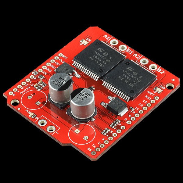
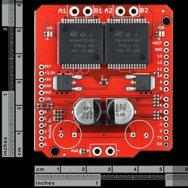
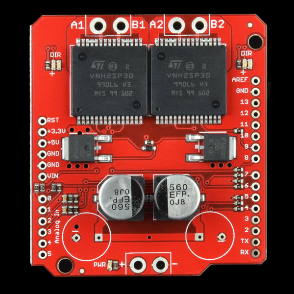
This is essentially a ramped up version of our Ardumoto motor driver shield. For this SparkFun Monster Moto Shield we've replaced the L298 H-bridge with a pair of VNH2SP30 full-bridge motor drivers. We've also beefed up the support circuitry so this board is capable of driving a pair of high-current motors! The VIN and motor out are pitched for our 5mm screw terminals (not included), making it easy to connect larger gauge wires.
Note: When using this board in extreme high-demand applications it may be necessary to improve thermal performance with a heat-sink or fan and to solder the wires directly to the board instead of using a screw terminal (in addition to the myriad other complications present in a high-current system) However, when using the board at currents up to 6A the chips will barely become noticeably warm.
- Voltage max: 16V
- Maximum current rating: 30 A
- Practical Continuous Current: 14 A
- Current sensing available to Arduino analog pin
- MOSFET on-resistance: 19 mΩ (per leg)
- Maximum PWM frequency: 20 kHz
- Thermal Shutdown
- Undervoltage and Overvoltage shutdown
- Schematic
- Eagle Files
- Datasheet (VNH2SP30)
- Example Code
- GitHub (Design Files & Example Code)
SparkFun Monster Moto Shield Product Help and Resources
Core Skill: Soldering
This skill defines how difficult the soldering is on a particular product. It might be a couple simple solder joints, or require special reflow tools.
Skill Level: Noob - Some basic soldering is required, but it is limited to a just a few pins, basic through-hole soldering, and couple (if any) polarized components. A basic soldering iron is all you should need.
See all skill levels
Core Skill: Robotics
This skill concerns mechanical and robotics knowledge. You may need to know how mechanical parts interact, how motors work, or how to use motor drivers and controllers.
Skill Level: Rookie - You will be required to know some basics about motors, basic motor drivers and how simple robotic motion can be accomplished.
See all skill levels
Core Skill: Programming
If a board needs code or communicates somehow, you're going to need to know how to program or interface with it. The programming skill is all about communication and code.
Skill Level: Rookie - You will need a better fundamental understand of what code is, and how it works. You will be using beginner-level software and development tools like Arduino. You will be dealing directly with code, but numerous examples and libraries are available. Sensors or shields will communicate with serial or TTL.
See all skill levels
Core Skill: Electrical Prototyping
If it requires power, you need to know how much, what all the pins do, and how to hook it up. You may need to reference datasheets, schematics, and know the ins and outs of electronics.
Skill Level: Rookie - You may be required to know a bit more about the component, such as orientation, or how to hook it up, in addition to power requirements. You will need to understand polarized components.
See all skill levels
Comments
Looking for answers to technical questions?
We welcome your comments and suggestions below. However, if you are looking for solutions to technical questions please see our Technical Assistance page.
Customer Reviews
4 out of 5
Based on 3 ratings:
1 of 2 found this helpful:
Great Motorshield and Great Customer Support
So I ordered this to resolve a over heating issue using an arduino motor shield. Worked great. I can run my bot now using 2x12v dc motors without issue.
My initial order a capacitor popped from a bad unit and the team at sparkfun responded quickly and got me a replacement for my project and answered my setup questions.
As good as I hoped it would be.
I put it into a balancing robot, a 5ft tall balancing robot weighing about 60lbs. or more. Each motor draws around 6A under light load, locked rotor is probably in excess of the 30A rating, but should never happen. I did have to add a heat sink. The motors are quite powerful with very snappy response. After trying several options, including some designs of my own, this is the first drive amp to actually work in this project. Thank you SparkFun for a drive amp that can drive sizable motors.
Plugged in, build code, and go
This was an easy setup to get up and running in the Studio 7. The software I pulled from the Googled tutorial had some issues, yet it was enough for me to understand the part and get some motors spinning. Careful when adding connectors to the shield; The USB to shield can be shorted out to the arduino if not careful, I almost made this mistake on first power up ... no sparks!!
-------------------- Tech Support Tips/Troubleshooting/Common Issues --------------------
Shorts?
After soldering the 5mm pitch screw terminals, try adding electrical tape on the bottom of the soldered terminals so it does not short with the pins on the Arduino.
Additional Example Tutorial and Reserved Pins
Quick tutorial explanation => http://garagelab.com/profiles/blogs/tutorial-how-to-use-the-monster-moto-shield.
Besides power, it just uses 2 analog pins, 4 digital pins, and 2 PWM pins to control the motors.
Datasheet of VNH2SP30 say "Logic input high threshold: 3.25 V min." what does this mean?
is this compatible with the Arduino Mega ??
Shouldn't the PWM value on a Arduino not be 0->255 instead of 0->1023 like in your example code?
what the value of BTZ52? 20V? 25V? and how many Volts are enough for the 560uF caps? all resistors with 5% tol its ok?
the mosfet FDD8580 can be the FDD8780? (the zener have to be different?)
and why the 2 cap 1000uF on pcb and not in the board?
look like my comment has been "purged"...... sad!!
http://dx.com/p/monster-moto-shield-for-arduino-red-161274 - Not cool, DX - Not cool.
You'd be surprised how many mimicking products we run into on other website retailers. If you're looking to buy a genuine Sparkfun product from somewhere else, but you're unsure whether it's from us or not -- you can always give us a holler at techsupport@sparkfun.com
with them, what you see , is probably not what you get...
Hah. I guess if they're gonna take the Eagle files to do their own run, they might as well be blatant about it. At least for Pro Mini they left the logo on ;\
79$ for two 10$ PWM drivers and a 30-min imprecise routing work? Awesome!
At least try to give correct usable specs instead of misleading absolute maximum ratings. And specify that you misplaced the two leds, they are going to burn at first >5V use.
If you're interested in an alternative, one of the #sparkfun frequenters is making a stackable motor shield so you can drive as many motors as any project may need. Just google for the key words there - it was recently covered on hackaday so I'm sure it's easy to find :)
Just like the Adafruit one? https://www.adafruit.com/product/1438
My memory doesn't go back four years on these topics, I'm afraid - but google+hackaday does: a stackable motor driver shield for the arduino
OK, some experiments just done with this circuit and I concluded that definitely it does not do what the features section promise:
- first of all the maximum voltage of 41 V is not usable at all due to the internal overvoltage limit of the driver IC (as already said by Member48425 in his/her comment). As specified in its data-sheet, the VNH2SP30 IC is for automotive applications for which the nominal working voltage is 13.8 V or so. The 41 V limit is an "absolute maximum rating" specification for VCC, that is the maximum sustainable supply voltage by the internal H-bridge. In my experiments the drivers gone in protection mode disabling the output when VCC rose over about 16 V and the only way to recover a normal operating condition was to switch OFF and then ON again the power.
- The current limit resistors for all LEDs are valid only for VCC of about 5 V! When I first saw the schematic diagram I though the values were wrong, but when I supplied the circuit a 24 V... they burnt in a few seconds, so I was forced to desolder them.
Definitely this shield was not a valid choice; I think I could find some more valid product for my needs!
THIS PRODUCT SHOULD BE IN Robotics| Drivers CATEGORY, THIS IS NOT AN ARDUINO, THIS IS A MOTOR DRIVER
HOWEVER, THIS PRODUCT IS ALSO AN ARDUINO SHIELD, THUS IT ALSO BELONGS HERE. QUITE THE PREDICAMENT.
...WHY ARE WE YELLING?
It's in both.
41V max? Those LEDs may not like 120mA of forward current.
true.
Why not buy one of these:
http://www.pololu.com/catalog/product/707
Or these:
http://www.pololu.com/catalog/product/708
And the more expensive VHN3 has the current sense circuit built in. Sure the form factor is not an Arduino Shield but they both cost significantly less.
http://www.pololu.com/catalog/product/2502 This one here does have the arduino pin layout.
Can someone explain how do I find the correct value for CS_THRESHOLD, what pin 13 (statpin) does and how to use it?
How could we add some extra layers of protections between arduino, this shield and the motors. Would this circuit work for using separated power supplies for both boards and opto isolators to isolate them?: http://i.imgur.com/1JbWVmr.png I can make sense of parts of it but I don't understand how it can work when all the collectors of the opto are connected to the same Vin, so all the pins seem basically bridged. What about the motors, is there any circuit you guys could share to protect against inductive kickback? I know the board has built in protections, but I know some people that burnt a few of them, and that makes me paranoid.
Because this shield uses pins 1 and 0, it's not compatible with Yun, correct?
Stupid question- are these stackable?
Sorry, but how can I connect this board to any stm32 board? It looks like a good idea to connect EN pins directly, INAs & INBs through Logic Level Converter (with BSS138), but how to connect PWM inputs? Main problem, as I understood, is that PWM inputs has pull-down resistor...
Is it compatible with the Raspberry Pi?
No, this is an Arduino shield. Check out the RaspiRobot Board, that might work for your needs.
I am confused on how to wire this shield to a motor with encoders, does anyone knows? Does inApin and inBpin have anything to do with the motor's encoders or is it separate ?
I am these are stupid questions, any good tutorial would be appreciated.
I have a PcDuinov2 (GPIO - 3V3). Could I use it directly with this shield or I will need a voltage translator 3V3 to 5V?
hello people I'm trying this code to make the motor turn to the right or left via potenviomentro, starting on low speed and as for increasing the graduation of the motor potentiometer will also graduating, if you make a smooth torque in the motor potenciomentro also starts soft but if you do a fast torque in the motor drives potenciomentro too fast, but the only thing I got is that the LEDs remain lit direct and very weak when I turn the engine off if the LEDs, since the potentiometer does not trigger anything like the help of the staff thanks
Can I control a stepper motor with this?
Yes it works. Just set the PWM pins to output and HIGH. For example the stepper_oneRevolution example works with this setup: Stepper myStepper(stepsPerRevolution, 7,8,4,9); void setup() { myStepper.setSpeed(300); pinMode(5, OUTPUT); pinMode(6, OUTPUT); digitalWrite(5, HIGH); digitalWrite(6, HIGH); }
But since there is no hardware current limiting, steppers get hot real fast. And since the drivers do not work at low voltages such as 3V that are suitable for a lot of steppers, that can be a problem. Solution: get 12V steppers. Better solution: get a stepper driver with current limiting.
What for are these FDD8580 mosfets are used? Only for reverse polarity protection or what?
What is the conversion for the Current sense to read amps on the Arduino?
This is what I calculated, but its way way off!
V=ADC_steps * (5/1024)
I = V/1.5kOHM
I = (ADC_steps * 5)/1024)/1500
I = ADC_steps/307200
But what I measured is way way off...
Through trial and error I found the constant to be 30.56... However I don't know how accurate that is because I measured the current with a MultiMeter.
Is it me or is there a mistake in the data-sheet? shouldn't Rsense be 1.5ohm instead of 1.5kohm... which would be 30.72 for the constant?
Hello Sparkfun ! I have the same question as Member #86519 and i didn't found the answer into the sample code : "How can we convert the value read by the Current sense ANALOG input Arduino's pin into current intensity ?"
thanks Mat
Hi, good to see you changed the 40V to 16V in the description.
I tried mounting 5mm screw terminals, and they overlap the H-bridge ICs. Please update the design for the next batch.
Should this work in a stack with Arduino UNO and XBee shield?
Given the price tag and the width of the output traces, am I correct in assuming that this board is manufactured very high copper thickness? To handle the full 30A with those output traces, you would need something like 6oz copper. Using a more ordinary 2oz copper PCB, those traces can only handle about 12A. If nothing else, that would explain why it costs so much for ~$25 of components.
Trace width calculator: http://www.4pcb.com/index.php?load=content&page_id=95
Will this work with a dagu 6WD chassis from pollou?
Basically can this board handle the following: ((7Amps3Motors)2Channels)
Also can this board pulse the motors?(PWM)
Yes, but you'd need 3 of them for all 6 motors.
there are only 2 channels. aka, two sets of 3 motors wired in parallel...
would it still be able to handle the current?
Ah ok. Then this should work.
I bought one of these 'coz I got a 4 motor Rover 5.
After looking at the board in mah hand...
There is NO WAY IN HELL I'm going to put it over my Arduino!
I'll mount it away from my Mega and just run ground, +5V and the control lines to it.
There is just not enough clearance on the motor supply.
I only got this to run my Rover 5 after I figured out 1 L298 per motor was not going to be enough.
So @ 6A it looks ok
This board design is ridiculous !
those ships are designed to hold 1000W of power EACH.
and the board could support 20W maximum.
Fan will not help much, the dissipation of the chip is from below.
It is like putting two jet turbines inside the trunk of a Nissan Micra, with the hood closed.
I bought one Monster Moto Shield and one ArduMoto Shield from a Sparkfun distributor and... I discovered that the stackable connectors and the screw terminal blocks are not included in the kit.
OK... one can say that they are not present also in the published pics, but why don't put a note in clear evidence (or in more evidence in case it is already there and I was not able to see it) on the description of the units?
Now I have two circuit which I cannot use until I receive the missing connectors that I ordered with additional shipping expenses... this is time consuming and truly frustrating!
I bought one of these, and the second controller does not work within the 30 day return period and customer service did not respond to my email. :(
Customer service had an interruption while they migrated to new servers - Upshot I did get good customer service and a replacement shield!
So is there a Sparkfun motor controller board which could drive two 24V geared wheelchair motors? At full speed with no load, they pull around 2A, but, of course, they can spike much higher and can pull around 10A with a decent weight load.
These H-Bridge ICs do not support 41V. I have worked with them and TI mentioned 41V in the datasheet, but over-voltage shutdown is at 16-22V.
30A of maximum current rating and the 6A value in the note are the total or are the value for only one motor?
The current and voltage ratings presented in the description are a bit misleading. While the driver can survive 41 V, it should not be used with voltages above 16 V because that is the point at which the overvoltage protection can kick in. Similarly, while the drivers can deliver a maximum of 30 A, they will overheat at much lower currents without the addition of a heat sink.
Correct. Reading the datasheet is always a great idea before starting a project.
So I can't use it with a 36V 12A motor ?
If so please update the product description with real-world data, not absolute-maximum-ratings. Please confirm that, I may return the product.
GND seems not very well designed: it is connected with GND comming from Arduino. Current returning to power supply will use this path if GND is unconnected on power connector J3. Small copper traces will literaly burn, acting as a fuse.
And GND trace width and route is not very straight to JP3. It will not be a problem at some amps, but with both drivers on at 30 amps..... :-(
What motors would be appropriate for using with this shield?
What do the two external mosfets do? Do they facilitate the under or over voltage protection?
Hard to tell. One might guess reverse polarity protection, but the only thing they'd be protecting is U1 and U2. C2 and C5 (polarized electrolytic caps) would still be exposed to the reverse voltage and would likely fail catastrophically. Vcc undervoltage? Maybe...below 3V or so the FETs would be off. That doesn't really matter, though, since the FET drains (rather than the sources) are connected to ground. All that happens when the FET is off is an extra diode drop, the FET's body diode, is inserted between U1/2 ground and system ground. Overvoltage? I don't see a viable mechanism for that. Puzzling indeed. D1 is a good addition, to prevent VGS overstress when Vcc > 20V.
Yes. The "typical circuit" in the data sheet for the H bridge has the cap minus terminal connected to the bridge common. This would have been better, if the idea was indeed a zero voltage drop reverse protection circuit (which I still suspect).
Thanks for pointing me to the datasheet...you're totally right, it's reverse voltage protection. I should've started there rather than spouting off based solely on the schematic. The FET/diode/resistor combo is in the application schematic in Figure 32, and section 3.1 addresses reverse polarity protection approaches. Cap negative to the H-bridge ground, as you point out, and it should be fine. Need a different FET though, as Abs. Max VDS for the FDD8580 is 20V.
All that leaves is the LED1/R20 path...what's LED1's reverse breakdown voltage (often 5V-ish) and what happens when you run 120mA backwards through him? Tying his cathode to the bridge common would solve that problem too. Finally, even in normal operation, at 41V all of the LEDs will be subjected to ~120mA forward current, likely at least double their rated capacity. Bigger resistors (intensity issues at lower Vccs?) or some Zener magic (cost?) are in order here. Rev. B? ;)
Even better, run them off 5V, switched with a FET from Vcc
Indeed, that's a fine solution!
It looks as though the voltage supplied from VCC after dropping across the 100k resistor is enough to turn on the Mosfet's and pull the GNDA/GNDB on the H-bridge to zero ground.
Reverse polarity protection perhaps.
Are the traces on the pcb large enough for 30Amps current?
They are actually C3 and C6 on the schematic---marked as DNP (Do Not Populate)
Why are there two unpopulated capacitor footprints?
I was unable to deduce from the skee-matic.
It looks to me like C2 and C3 in the upper-left corner of the schematic.
Large power caps to handle spikes caused by high-current motors starting.
I guess you add those yourself if needed.
Look at the silkscreen there right under the populated ones