- Home
- Product Categories
- Sensors
- 9 Degrees of Freedom - Sensor Stick - Ding and Dent

9 Degrees of Freedom - Sensor Stick - Ding and Dent
Replacement:SEN-10321. We fixed the missing trace on the new version. This page is for reference only.
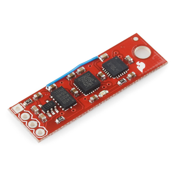
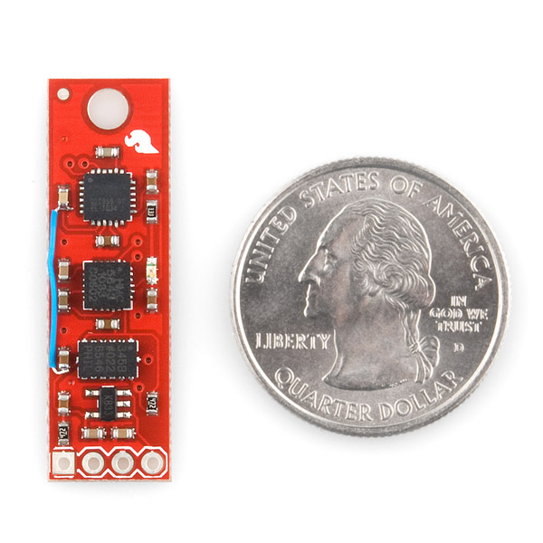
The 9DOF Sensor stick is a very small sensor board with 9 degrees of freedom. It includes the ADXL345 accelerometer, the HMC5843 magnetometer, and the ITG-3200 gyro. The 'stick' has a simple I2C interface and a mounting hole for attaching it to your project. Also, the board is a mere 0.036" thick (0.093" overall), allowing it to be easily mounted in just about any application.
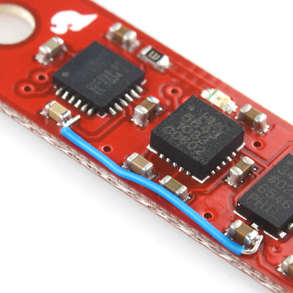
Note: There was an error with the board for this batch. We forgot to include a trace, so there is a wire correcting the error. Please check the pictures. There is a now a new revision available which fixes this missing trace (as well as replacing the now EOL'd HMC5843 with the newer HMC5883L) However, if you don't mind the 'greenwire' fix, you can grab this board at a reduced price and it will work just fine.
**We cannot accept requests, returns, exchanges, provide documentation, or provide support on any aspect of these boards. **
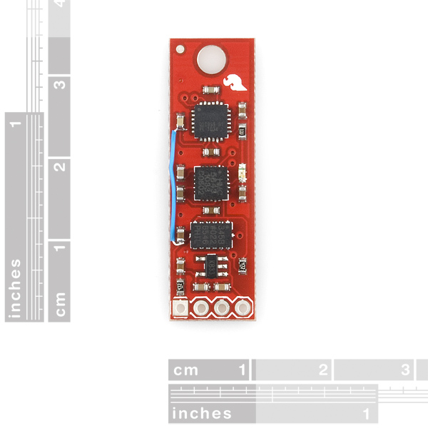
- 1.37x0.42"
- Schematic
- Eagle Files
- Datasheet (ADXL345)
- Datasheet (HMC5843)
- Datasheet (ITG-3200)
Comments
Looking for answers to technical questions?
We welcome your comments and suggestions below. However, if you are looking for solutions to technical questions please see our Technical Assistance page.
Customer Reviews
No reviews yet.
noworries:
You guys don't know me. You think you know me...
You Sir! You have made me laugh! I see your point but 'nine-dee-oh-eff' kinda rolls of the tongue better.
If the rate gyro were perfect, one could determine the attitude of the sensor platform over time in reference to its starting position by integrating the rate gyro outputs with respect to time. Unfortunately, no rate gyro is perfect, so attempting to do this will develop an error that will cause your estimate of attitude to be incorrect. If you do not limit the magnitude of this error, the longer you use the sensor platform outputs to estimate the sensor platform attitude, the less accurate the attitude estimate will be, to the point of it being completely unreliable. A method of limiting the attitude estimate error in pitch and roll uses the Earth's gravity and an assumption that the sensor platform is currently not being accelerated. This allows one to sense in three dimensions where "down" is by using the accelerometers and to provide a small correction signal to your attitude estimate for pitch and roll. The magnitude of this correction signal is limited to be no larger than just slightly more than the maximum drift rate that the rate gyro has. This leaves the yaw axis drift error uncorrected. To limit the yaw axis drift, the magnetic field of the Earth is sensed by the magnetometer and a small correction signal is applied to the yaw attitude estimate.
To determine your location in reference to your starting point, you could integrate the outputs of the accelerometers and apply this three dimensional acceleration in conjunction with the attitude estimate. This position estimate then would be subject to long term drift errors associated with the accelerometers. So, a GPS sensor comes to the rescue. For aircraft applications, a baro sensor can be used to assist in maintaining the desired altitude, and a airspeed sensor can be used in addition to the accelerometer outputs to provide a better correcting signal for pitch and roll attitude error limiting purposes during accelerated flight, I.E. climbs, decents, turns, and changes in airspeeds.
By the way, I now have one of these sensors on order to play with.
For anyone who just wants to get this working, I've got some example code with all of the I2C addresses, registers, initialization steps, etc. worked out here: http://wp.me/p1CQVj-1v
Hopefully I'll add some calibration to it soon.
Hey guys and girls, I just updated the firmware at http://dev.qu.tu-berlin.de/projects/sf-razor-9dof-ahrs to be compatible with this board...
I thought this could be useful to some of you!
Cheers!
It would be great if there was a daughter board in the future that had the same dimensions and had an Atmel uC, temp sensor, batt charge/monitor on it and could be layed/mounted right overtop of this board. Makeing it a small stick that does it all!
Im actually working on a shield design for the Teensy Microcontroller, so that you can get the 9DOF board and just attach it and power it via the Teensy. Also Ive got multiple other Shield designs in the works (and prototypes being tested) so that all you need is a Teensy, my shields and a battery and you're good to go.
Hi, I'm probably doing something wrong here, but the RAW_DATA_RDY is always 0. I believe I set the RAW_DATA_EN to high. I'm programming for the Adruino Uno. Thanks in advance. Um, it seems I cannot put all the code here....
I bought this sensor stick and tried using it with Arduino Mega and the Razor AHRS library. I found that there is a lot of drift in the yaw direction, pitch and roll are stable. Furthermore, I found that the drift worsens in yaw if you bring a ferrous object near the sensor, pitch and yaw remain the same. Can someone suggest how to get rid of the drift in yaw?
Thanks,
Um I'm a little late to the debate here but I'm fairly certain that degrees of freedom is a differential equation phrase representing however many factors that may be varied in the equation. For instance in common transient RLC circuit analysis you deal with differential equations containing 2 degrees of freedom.
Any chance we'll see an updated sensor stick soon with a MPU-6050 and a HMC5843?
Here's some arduino code we whipped together to read the accelerometer: https://gist.github.com/1239034
#include
#define DEVICE (0x53) // ADXL345 device address when the SDO pin (12) is grounded
void setup()
{
Wire.begin(); // join i2c bus (address optional for master)
Serial.begin(115200); // start serial for output
// Wake up the accelerometer
Wire.beginTransmission(DEVICE); // Start talking to the ADXL345 accelerometer on the SEN-10183 board: http://www.sparkfun.com/products/10183
Wire.send(0x2D); // The address on the accel we want to set: POWER_CTL
Wire.send(8); // The value on the address: Measure(8)
Wire.endTransmission();
}
And the rest:
void loop()
{
// Ask the accel to send us it's XYZ values
Wire.beginTransmission(DEVICE); // Start talking to the ADXL345 accelerometer on the SEN-10183 board: http://www.sparkfun.com/products/10183
Wire.send(0x32); // The address on the accel we want to read
Wire.endTransmission();
// Receive the XYZ values
Wire.requestFrom(DEVICE, 6);
byte data[6];
for (int i=0;i
Ok looks like the comment thread has garbled the code. You can just see it here:
https://gist.github.com/1239034
I am pretty green in this area and fascinated by the capabilities of the 9 DOF sensor stick. I have so far tried getting outputs with two axis accelerometers and 1 axis gyro. Outputs are not easily understandable (e.g. When I oscillate a torsion pendulum I get oscillation around channel No. 610. Why? It should have been 512th channel where the pendulum passes through 0 degree (highest rotational velocity! Given this problem, I beg someone to help me finding the instantaneous directional vector of a box which is arbitrarily moving/rotating around from these 9 DOFs. Is there a programme readily available which combines these outputs and spits out the Euler angles, just like Shake/SK7 which I just discovered on the net? I would have been happier if the clock were also attached.
Hi,
I bought this version in a swedish store a couple of weeks ago. Didn't have time to test it out until now. My version does have the HMC5843 magnetometer but not the wire fix showed in your pictures, guess it has been sitting in their storage for a while. What is "a trace" and what are the consequences if don't add the wire? Is this a minor cosmetic error or is the magnetometer output useless? I'm new to this but I've hooked it up to a Arduino Uno and get readings from all three sensors. The magnetometer stream plausible values, meaning it reacts properly on movements and doesn't spit out randomly numbers. What's your recommendation?
If the board doesn't have the wire, it doesn't need it. The first round of boards needed the wire to replace a missing trace (a copper path on the board surface which is the equivalent of a wire). Subsequent boards do have the formerly missing trace, and don't need the wire. If you're getting readings from all 3 sensors, your board is working perfectly!
Has anyone tried to hook one of these up to a Basic Stamp II? Maybe some demo code? Or otherwise some demo code for some other microcontroller?
Interesting - though I'm curious how this compares with Atmel's own ATAVRSBIN1 board at 60% of the price: http://www.atmel.com/dyn/resources/prod_documents/doc8354.pdf
Worth a look...
Does anyone have any example code for this board? Is it just a case of using the example code for each of the sensors and combining them? Or is there a good working example out there that spits out values from all 3 sensors?
Would love to see some examples
Shouldn't this have "Replacement: SEN-10321" up at the top?
How the hell do you connect this to an arduino? Perhaps you could supply a wiring diagram and some example code, or at least a quick description?
I connected it up with SDA/SCL going to pin A4/A5 on the arduino, and +5V/0V going to Vcc/Gnd, as seemed obvious from the lack of description. None of the chips respond to my register queries though. I read noworries' comment about the pull-up resistors in twi.cpp and tried that but it didn't work either.
I'll be pretty -ing pissed off if this expensive produce is somehow incompatible with the most popular microcontroller available, and you didn't even give a warning!
Finally you guys seem to have followed my request at having the I2C port on these boards... :)
Maybe you have realised how much of a pain the previous serial only version was...
Lol, was only joking, really great product as usual, thanks for your work !
dan
Hi,
I have seen a lot of information about each module separately but i couldn't find any info about the sensor stick as a whole.
Can someone tell me how to extract data from the device?
is there a written code i can use?
Do I need a specific micro controller to work with the sensor stick?
Thanks a lot,
Omry
Gyro works great, accel too ...
but with the mag, something is screw...(ed)
I am getting values from the HMC (16 bit int) like...
-1, 3, 0
4, -2, 1
-5, 1, -3
with no correlation to orientation at all. Other values read from the HMC are fine eg. device id, config regs etc
Could this be the 'cap esr' issue mentioned in various forums ...anybody got any suggestions???
Cheers
Mike
I want to use this with an Arduino, which means I want to build a level-shifter for the i2c lines, as seen in this page:
http://www.nxp.com/news/backgrounders/bg_esc9727/index.html
The board doesn't export its 3v3 regulated output. If I feed it 3.3V pre-regulated, is the regulator dropout low enough that 1) the board will work; 2) the level-shifter will work (if I put the pre-regulator "vcc" into the base of the MOSFETs)?
Or do I need to solder on a wire and bring the 3v3 back off the board?
Thanks...
Is the schematic correct?
It has pin 7 of the ADXL345 tied to 3.3V. But this is the CS/ input - shouldn't this be tied low?
John
Yes, the schematic is correct. The ADXL345 uses the /CS pin tied high to enable I2C mode communications. See page 8 of the datasheet for a more detailed explanation.
Do I need a logic level shifter to hook this up to the SDA/SCL lines of an arduino?
A level shifter will not be necessary to use this board when the Arduino microcontroller is powered at either 3.3V or 5V.
The ATMega328 when used at 3.3 volts will obviously not require a level shifter.
When used at 5 volts, the specsheet for the ATMega328 says that the minimum voltage that is guaranteed to be detected as a high is .6 * VCC or .6 * 5.0 = 3.0 Volts. So the sensor stick's 3.3V output should work fine.
Keep in mind that the 3.3 volt level is only 300 millivolts above what is considered to be a valid high, so you will need to keep the wires that connect the sensor stick to the Arduino as short as possible to avoid the possibility of electrical noise exceeding the 300 millivolt noise margin.
I spoke too soon in that last comment, there is a problem in the sensor stick accepting voltages that exceed 3.3 volts, so direct connection when the microcontroller is powered by 5.0 volts does not appear to be possible or recommended.
It may be possible to clamp the voltage to a safe level by inserting a series resistor in the SDA and SCL signal path between the Arduino and the sensor stick, along with a pair of schottky diodes which have thier cathodes connected to 3.3 volts.
(This would clamp the signals that the sensor stick ICs see to 3.3V + 0.2V = 3.5V which should not damage the inputs to the ICs on the sensor stick.)
If anyone has a circuit that they have tested, please feel free to submit a link to it.
Thanks.
Well, as it has been a while since I have used I2C, I should have waited a bit before commenting... After further analysis the I2C master does not drive the SCL or SDA lines(it just lets them float to the level the pullup resistors are connected to) so direct connection should work fine.
Thank you for your responses. I was paranoid about it, so I rigged up a 2-mosfet level shifter before I powered it up. the accelerometer and gyro work fine, but I'm getting no responses from the magnetometer. I'm pretty sure my board has a bad one. I've got an email in to sparkfun tech support. I hope these things are still in stock and they can send me a new one!
I would check the I2C address you are sending to the HMC5843.
I have successfully used an Arduino to read the device ids from all three of my sensors on the sensor stick.
The datasheet for the HMC5843 has an error in it that if not caught can lead to a lot of confusion. It states on page 18 that "The default (factory) HMC5843 7-bit slave address is 0x3C for write, or 0x3D for read operations."
This is incorrect, the correct 7-bit address for this device is 0x1E which results in the 8-bit patterns of 0x3C for writes or 0x3D for reads.
The Wire Arduino library expects you to pass in 7-bit I2C addresses.
Hope this helps.
BTW, I modified the Wire library to disable the Arduino internal pullup resistors and am having no problems with a direct connection to the sensor stick from my Arduino.
Thanks again! I was using the 0x1E address, so I don't think that is it. I'm going to try to disable the arduino pullups and see if that helps (not hopeful). I found a thread on the arduino forum where a guy was having problems the the HMC5843 breakout. He ended up having to get two replacement boards before his started talking, so I suspect there were some bad chips in the reel. The thread contained some dead-simple code that did not work on my board. I also modified one of the wire library scripts to just read back the first register on the chip, and it also didn't work. The ADXL345 and ITG3200 work just fine.
Also, keep in mind that the stock implementation of the Wire::Begin() code enables the 5V internal pullups. This can be modified by changing a couple of lines in twi.c
The schematic does not specify which device U4 is - what voltage range can this board accommodate?
The voltage regulator IC appears to be a Micrel MIC5205 which has a marking of KB33 to indicate a lead free fixed 3.3 volt output. The datasheet indicates that the maximum recommended operating voltage is 16 volts.
The datasheet is available at:
http://www.micrel.com/_PDF/mic5205.pdf
Hope this helps.
Perhaps someone on the design team for this board can verify that the voltage regulator is as I have indicated.
Thanks.
I'm from Portugal, and that would be awesomme, is there any topic in some forum about the new group buy?
Just get in touch with me. My mail is fvaresano at yahoo dot it.
I still did not posted on any forum about the new possible group buy.. I'll do that soon.. meanwhile write me an email so that we get in touch.
Any one knows where can I buy some ITG-3200 bare chips?
They are only available from invensense.com (worldwide shipping) or cdiweb.com (USA, Canada & Mexico).
If you are in Europe, you only can use invensense.com but they will charge you 50$ for shipping and you'll also have to pay the Customs duties and VAT (~ 20%).
I'm probably going to buy from invensense.com soon and have them shipped to Italy. In the past, me and some other hobbyists organized a group order from them so maybe if you are in Europe you can get in touch with me.
Awesome!I was going to use all three of those sensors on a project and this simplifies things immensely.Only thing is I need to step up my vcc (1.8v) to 3.3v not regulate it! That's an easy fix though.
I'm sorry guys, I was 4 days ahead of you ;-)
http://www.varesano.net/blog/fabio/freeimu-designing-free-speech-9-domdof-marg-imu
Well, technically, our first prototype build was the first week in October. Nice job on yours.
RobertC.:
You must be kidding, no?
I laid out the board to minimize board size. I disregarded the axis locations because in my mind, the axis are simply a number. I assign my own coordinate system once I get my project up and running. As long as they are orthogonal, I don't think it matters where 'X' on one IC and the 'Tree' on another IC are located. The output is all that matters.
Nerd fight! Who brought the pies?
I brought pies. What it COULD use is a 3-pad solder jumper to switch all three ICs to their alt addresses. Or, alternatively, I'd take a second variant of the board. I haven't actually looked to see if this is feasible in the same board footprint. Just sayin': it would be nice to be able to string two of these together for limb tracking.
I'm not kidding. Having teaching experience, I do know that people get confused for lot less. Moreover, note that this isn't documented on your current product page.
Anyone knows that you just swap x and y and you are ready to go. But, IMHO, sacrifice a couple of mils for the ease of use is not a bad thing to do.
I'll count the number of people who will try my 9DOM sensor fusion algorithm implementation and will stuck on this.
Oh wait... you did.
yeaaaaah... I've been implementing sensor fusion algorithms with this board for a week now. I don't think that anybody with a head for AHRS devices is going to have a problem with this. That's just freakin' gratuitous. Align 'em on your own damn board.
I agree - all the other boards (like Razor IMU (9 degrees of measurement) or IMU Digital Combo Board (6 degrees of measurement)) align, which makes it easy to use and the silk screen less cluttered. It is too bad that this board has such a big design flaw. I was thinking of buying this today, but now I will wait for version 2, which hopefully will fix the misalignment...
Really? The 9DOF Razor's axes do NOT align. It's right there on the silkscreen. But since the aberrant set of sensor channels is going through the ADC, while the other two are digital, perhaps it's more obvious that the naming is arbitrary because you aren't hitting registers called XDATA (or whatever) and so on. Now buy the board if that was all that was keeping you from doing so.
Just swap the x and y axis when reading the sensor data.
9DOF? Technically, a bit of an overstatement in my opinion. This sensor board has the ability to detect angular rotation in three axises, and linear acceleration in three axises. That is a total of 6 degrees of freedom. By integrating the outputs of these sensors correctly, one can determine the orientation and location of the sensor board in 3 dimensions. The fact that you also can measure magnetic field strength in 3 axises does not allow you to claim 9DOF, since this sensor outputs data that is correlated with that of the gyro sensor. The benefit of the magnetic sensor is that it allows one to compensate for the offset errors of the gyro sensor in IMU applications. Still a cool board, however.
Can we just compromise and say it's a 7.5DOF?
Agreed. You might consider what it would mean to add a GPS to this board - Would that give you 12 DOF? No, it would only serve as a reference for your accelerometer data.
The parameters being measured are the linear acceleration and rotational acceleration, both in three dimensions. With those six dimensions, you can measure any change in position or orientation.
The magnetometer (and hypothetical GPS) work in those same six dimensions, but they would give data about the absolute location of the device rather than its acceleration.
This is a six DOF board with an absolute reference for angular orientation.
Using that same logic you would also have to say that the gyro does not qualify, as it creates data that could be derived from the accelerometer. While a gyro/accelerometer combo can be used for dead reckoning, it would accumulate errors overtime that would it useless as a heading reference. <br />
<br />
The accelerometer directly measures translational acceleration in 3DOF, the gyro directly measures angular velocity in 3DOF, and the magnetometer directly measures absolute heading in 3DOF, hence 9DOF.
Actually, accelerometers can only detect tilt by using gravity as a reference, and then it's only in two dimensions, not three. True detection of rotation is possible even in a zero-G environment, but only using gyros, not accelerometers, though accelerometers would still be able to detect displacement.<br />
<br />
The key thing here is that acceleration and rotation are inertial measurements that don't require any external reference to measure. Orientation, which is provided by the magnetometer, requires an external reference (magnetic north). It can help compensate for measurement errors, but it doesn't contribute to the object's freedom of movement.
All 3 of you are assuming too much about this board. Sparkfun does not force you to use any one of the sensors as compensation for another. This board gives 9 independent axises of sensor measurement. Do with them whatever you want. The output of this board is 9DOF!
Give this guy a prize!
He's right, it has 9 degrees of sensors. Read it and implement it however you want.
So, you should call this 9 DOM (Degrees of Measurement).
Using DOF here is just the wrong terminology (even if it has became quite a standard in lot of websites and products description).
In robotics, for example, a 9 DOF robot arm means that it has 9 movable joints usable to position the hand in a given position.
Is the prize one of these boards? :)
You are quite the optomist :-)
I love I2C, two wires on my arduino and I can hookup everything.<br />
<br />
Already got a real time clock module and 16 x 2 text display sharing the line.
definitely a space saver for UAV versus individual breakouts, though might also be useful for hobbiest UUV designs
If it only had a baro/temp, it would be complete.
This is awesome! Also, thanks for including the eagle files! I want one of these with a battery charger and a bluetooth transmitter, and this will save me some time!<br />
<br />
Though I do want to throw an AVR on there too... Do you guys think you might just share the files for the Razor IMU any time soon? I'd gladly share my bluetooth+battery version with you!<br />
<br />
And actually I think it might make a lot of sense to have a battery powered bluetooth IMU! Have you guys thought of just adding that to your Razor IMU? You might be able to add the pads without actually stuffing them for the regular product...
I just posted the eagle files for the 9dof.
If anyone is interested in peeking at the design, images of the gerber output are here:<br />
<br />
http://circuitpeople.com/ViewPackage.aspx?id=36eada6d-5b66-4b63-87ad-9fb55449d065<br />
<br />
Nice to see that wayward trace found its way home. :)
Wow, you guys are the best! I really love that you share schematics and eagle files. Just little things like checking a battery charger or FTDI circuit makes it great to have. And you even share complex boards like the razor! :)<br />
<br />
What's a good way to share designs when they're completed? Is OpenCircuits the place for that? Or if I make a good clean board should I send it to you guys? :)<br />
-Taylor
You get what you see in the picture. We have corrected the issue.
Also, we have a small batch of these coming within the next day.
Is the flawed version of the board marked down in price?
Yes. It will normally be $99.95.
Wait...so do you guys solder in that missing trace for this first batch, or do we take care of that? Just wondering if I need to break out the small-diam. wire.