- Home
- Product Categories
- Robotics Kits
- Ardubot Bare PCB

Ardubot Bare PCB
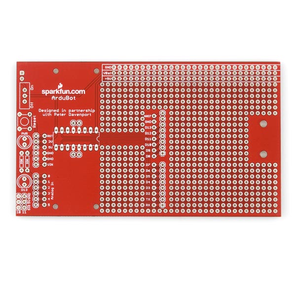
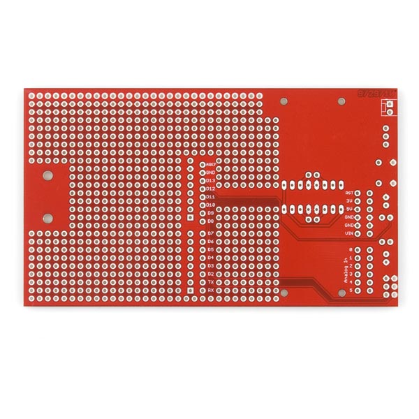
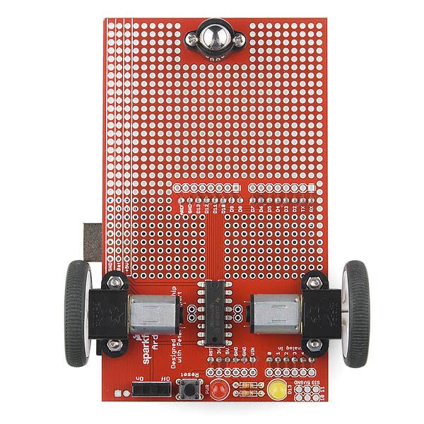
The new version of the Ardubot PCB breaks out all the Arduino pins to a separate row of headers. It also includes spaces for LEDs, a reset switch, and servo headers.
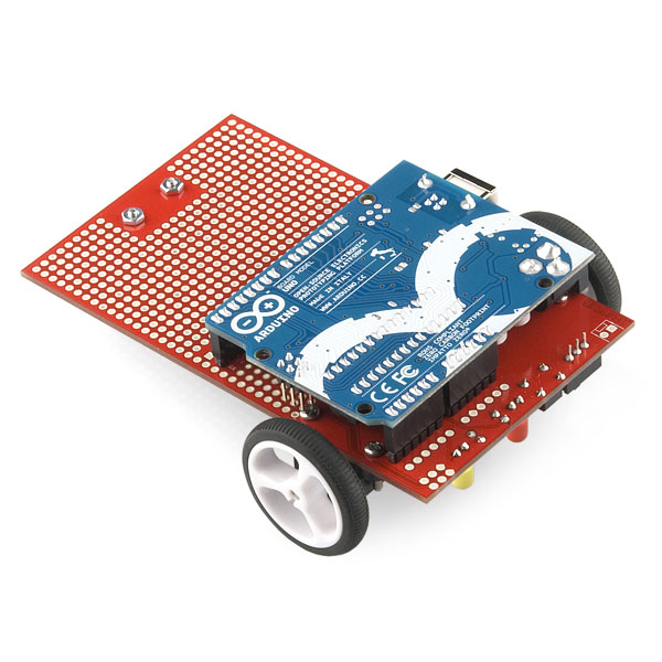
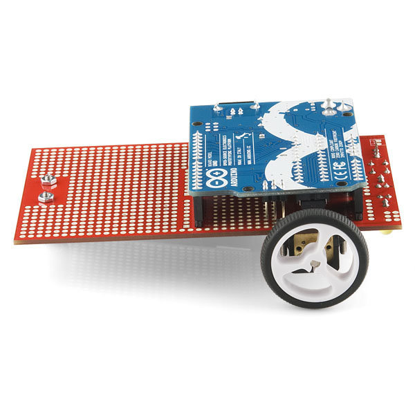
The Ardubot PCB can be the foundation of your own Arduino-powered bot. When combined with a few other SparkFun offerings, the Ardubot makes a great mobile testing platform. Or you could just go terrorize the cat and annoy your family and friends. Add some lasers and theme music and you can start your own battle-bot league!
The Ardubot PCB is designed to be mated with a standard Aduino Pro (3.3V or 5V) or Arduino USB board, along with 2 motors, a front caster and a bridge driver. All the Arduino pins are broken out to the Ardubot PCB, along with a generous amount of prototyping area and power busses that run the length of the board.
Check the associated items for build options and check the tutorial to put one together.
Note: We are working on updating the pictures to show a built kit with the new board.
Note: This product is a collaboration with Peter Davenport. A portion of each sales goes back to them for product support and continued development.
Replaces:ROB-09207
- 4.6 X 2.7" (117 x 69mm)
Ardubot Bare PCB Product Help and Resources
Core Skill: Soldering
This skill defines how difficult the soldering is on a particular product. It might be a couple simple solder joints, or require special reflow tools.
Skill Level: Rookie - The number of pins increases, and you will have to determine polarity of components and some of the components might be a bit trickier or close together. You might need solder wick or flux.
See all skill levels
Comments
Looking for answers to technical questions?
We welcome your comments and suggestions below. However, if you are looking for solutions to technical questions please see our Technical Assistance page.
Customer Reviews
No reviews yet.
This is retired. Who was its replacement?
This doesn't really have any direct replacements, but check out the shadow chassis and/or the redbot kit.
Is this intended to be powered by a single supply? Shouldn't the motors be powered separately? I assume the power header is used to power both the Arduino and motors, but would powering the Arduino using the barrel-jack work?
If I buy the current version of the board, can I use it with an arduino UNO without extra steps? This tutorial links to the version listed as replaced by the UNO and it's my understanding that the UNO is smaller...
The uno will not require any extra steps. It is actually pictured in the snapshot of the assembled robot.
Would it make more sense to mount the yellow and red LEDs upside down so they are visible while the robot is running?
Since this is a kit you can solder it together with the LEDs on top or the bottom.
Did you move the arduino mounting a bit more forward so the USB connector won't snag a wheel like what happened in the tutorial?
On this new version of the Ardubot PCB there is no conflict between the Arduino USB connector and wheel, use the recommended 32x7mm wheel size and there should be no trouble.
But still the Arduino ICSP programming header hits one of the mounting screws for one of the motors, to fix this problem reduce the height of the screwhead by 1 mm using a flat metal file.
I like this one, but no example software? After some testing I found out that the right motor is controlled by digital pins 9 and 6, the left by digital pins 3 and 5. The motor driver chip has both enable pins connected to +5V. Precise speed control can be obtained by using code like this:
void rightForward(byte speed){ // Motor code blocks
digitalWrite(9, LOW);
analogWrite(6, speed);
}
void rightBackward(byte speed){
analogWrite(9, speed);
digitalWrite(6, LOW);
}
For complete code examples, including code for wireless Nunchuck control, visit this page
Thanks, I wish they would either update the schematic or at least put a comment saying it is outdated, I thought I was going nuts until I read your post.
It would have been nice to bring the analog pins over to the edge of the prototyping area, but overall this is a big improvement.
Strange! New board but old mistakes!!!<br />
Why you didn't add protection diodes?<br />
Why you didn't add addition logic for select direction by one pin?<br />
Scheme not available. Are you support PWM control motors?<br />
The lack of a protection diode was an oversight but it would have been hard to fit on the board, most of the real estate was already taken up.<br />
Logic for pin selection would have made the board much more complex and would have been useless, you would have still needed 2 pins for each motor, one for direction and one for enable. With this design 2 pins are used for each motor, one for controlling the voltage of each motor led.<br />
You should petition the tech support people for the Schematic, I am sure they would put it up.<br />
PWM has always been supported.