- Home
- Product Categories
- Power Charger
- SparkFun LiPo Charger Basic - Micro-B

SparkFun LiPo Charger Basic - Micro-B
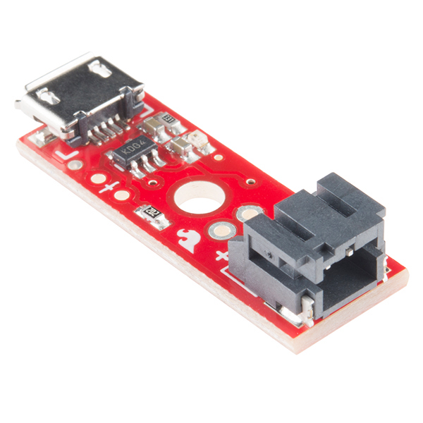
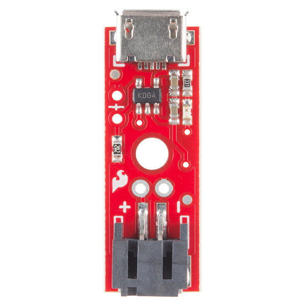
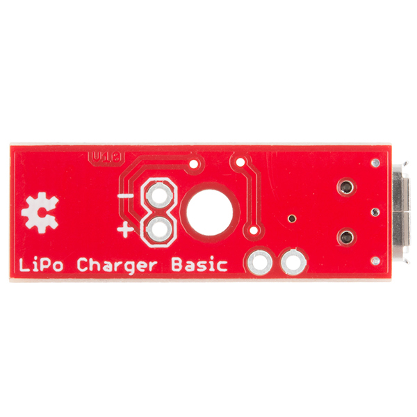
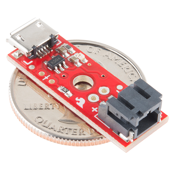
If you need to charge LiPo batteries, this simple charger will do just that, and do it fast! The SparkFun LiPo Charger Basic is stripped down of all features and just does one thing well - charge 3.7V LiPo cells at a rate of 500mA. It is designed to charge single-cell Li-Ion or Li-Polymer batteries. Check the datasheet below to see if it will work with your battery.
The board incorporates a charging circuit, status LED, connector for your battery (JST-type used in the batteries we carry), and a Micro-B connector. A small mounting hole allows this charger to be easily embedded into a project.
Note: This version uses a Micro-B cable. We also have this charger with a mini-USB connection as well.
- 29.4x10.8mm
- Schematic
- Eagle Files
- Datasheet (MCP73831T)
- GitHub
SparkFun LiPo Charger Basic - Micro-B Product Help and Resources
6 of 6 found this helpful:
MCP73831T STAT Pin and STAT LED
If you look at the datasheet for the LiPoly USB Charger's IC controller, the LED is connected to the charge status output (STAT). This is an output to indicate the charge status which is explained in section 5.2.1 in table 5-1:
Shutdown: Hi-Z (High-impdedence mode)
No battery present: Hi-Z
Preconditioning: L (Low)
Constant-Current Fast Charge: L
Constant Voltage: L
Charge Complete – Standby: H (High)
Since the cathode (-) of the LED is connected to the controller, setting the pin low turns the LED on; setting the pin high (or putting it in high-impedence mode) turns the LED off. From the datasheet, this unit features “AutomaticPower-Down." So when the battery is fully charged, the LED should turn off and the charge IC controller should turn off. This can fluctuate back and forth with charging depending on if there is some small discharge with the LiPo battery.
7 of 7 found this helpful:
Charge rate
The default charge rate for the LiPo Charger Basic is set to 500mA. The default output from a standard USB port is 500mA. In general, if you are charging your LiPo at a fast rate past the charge current specs of the battery, the life of the battery will go down. Looking at the charge rate for the battery, it looks like the recommended charge rate is 1C (or 400mA). I recommend changing the resistor that is on board to reduce charge rate. You can add some resistors in series between the PROG pin and resistor labeled 202 (this would require cutting a trace) or replacing the surface mount resistor with a higher resistance value. You can calculate the resistor value with the equation that is presented in section 5.1.2 Current Regulation Set (PROG) of the datasheet http://dlnmh9ip6v2uc.cloudfront.net/datasheets/Components/General%20IC/33244_SPCN.pdf.
Core Skill: Electrical Prototyping
If it requires power, you need to know how much, what all the pins do, and how to hook it up. You may need to reference datasheets, schematics, and know the ins and outs of electronics.
Skill Level: Noob - You don't need to reference a datasheet, but you will need to know basic power requirements.
See all skill levels
Comments
Looking for answers to technical questions?
We welcome your comments and suggestions below. However, if you are looking for solutions to technical questions please see our Technical Assistance page.
Customer Reviews
4.2 out of 5
Based on 26 ratings:
3 of 3 found this helpful:
Small, simple and inexpensive
The footprint is tiny, the operation is simple and the price is right. As other reviewers have suggested, it would be nice if the LED gave more indication than on and off. I can't tell whether it isn't hooked up correctly or if it is hooked up and done charging.
My other suggestion would be to expose a 2-pin header for for the 5V power input. I have it mounted in a tight enclosure where there isn't space for a USB plug, and I wanted to be able to connect it to a panel-mount barrel connector.
1 of 1 found this helpful:
Great form factor, but having issues
I've bought five of these and I have been having some trouble. It seems that they will charge for a few minutes and then stop or they will not charge altogether. I love how small it is and I am using it in a project, but perhaps the mini-usb version will be a bit sturdier and less finicky.
2 of 2 found this helpful:
The best thing out there but even improvable
I love this product ! I buy more and more. But sometimes I would like that the staff reply to the comments below the product .
and maybe make one with a cutoff circuit (like in the mac books !!! ) please .
When the power is connected battery charging and power via 5v usb, when the charger is unplugged battery takes the relay
Thanks for the feedback. I have passed this along to our engineer in charge of this product for consideration for revision. Thanks and happy hacking.
1 of 1 found this helpful:
It's Exactly as Advertised
The builtin header fits many common LiPo battery connectors without any modification, but the pads also allow you to solder on any other connector you might need.
1 of 1 found this helpful:
Careful
If you are going to attach this to another project be careful. I soldered two male headers to the +/- pads in the picture after checking the schematic. Should have worked imho. I pluged it in and now it is toast. Still not 100% on what I did wrong so I couldn't tell you.
2 of 2 found this helpful:
Simple but works fine
Lacking a proper connection to large copper areas, the charger chip gets quite hot at the start of charge. I would not reduce the set point resistor to use this with larger batteries, just live with the fact that it will take longer to charge. Or use the smaller battery it is designed for, around 500 mAh..
With this caveat, the charger works well and makes it easy to use LiPo cells in many projects. The micro USB extends over the edge of the board a little so it can be mounted in a case with an opening for a standard USB micro cable.
You should be using cells that have an internal protection circuit with this charger. Most of the familiar cell phone style batteries have internal protection. Cylindrical quad copter style batteries often do not have internal protection.
The charger has no undervoltage protection. If you over-discharge a cell it may not be possible to recharge it, So the attached circuit should have some kind of auto shutoff when the battery is low.
The red LED just shows that it is charging. When charge is complete, it goes out. In an actual unit it would help to have another LED (maybe green?) to show that the charger is plugged in. It would be easy to add this, just tap into the 5V from the micro USB and use a resistor to limit LED current. If you use a dual LED it would do the familiar "amber when charging and green when charged" scheme.
1 of 1 found this helpful:
Small Size, Can't tell if working
The product seems to work, but the LED on the charger doesn't light up. It"s hard to know how long I should keep the LiPo plugged in for full charge.
1 of 1 found this helpful:
Works good
Jest got through test charging the first battery (18650 2000mA), had to find out how the charge indicator worked, " RED While charging, OFF when finished, makes a quick flash when plugged in to the USB and no battery load". Wish I could get the mating connector with Red & Black pigtails for battery but did not find them on the web site as separate Items.
2 of 2 found this helpful:
I, too, would *LOVE* to see holes for access to Vin.
I'd like to imbed this, but I'm not even going to try to take that USB connector off or solder a wire in there. [I'l probably buy a bare Micro USB plug and use that.]
1 of 1 found this helpful:
Basic but does the job
I'm using this to charge batteries for a cycling headlight whose USB charger has failed. Seems to work just fine. It is skimpy on status, the LED is off whether fully charged or disconnected. I would like it to blink when charged to tell the difference.
1 of 1 found this helpful:
works great
Just plug it in and it charges batteries, at a low cost and no trouble whatsoever.
Nice little charging unit
I bought this for a project I was just trying out and wanted to include a rechargeable battery instead of a coin cell. It does the job nicely and I would consider using it for other projects. In fact I'll probably try to build more of these rechargeable batteries into my projects so I can charge up more devices.
Very good simple basic charger
Very small and easy to connect. The only thing I would do to improve it is to make the current adjust resistor easier to change if you want to reduce the charging current.
Small and good
Charger of small size, since I have it worked well, with the SJT input is less likely to connect it in reverse.
perfect little easy charger for single cell projects. inexpensive so i can give them out with the project. everybody knows how to use the thing, even the dog
Does its job
Does its job as advertised. Overall, glad I bought it.
The chip gets painfully hot, but not catastrophically hot, and a high temperature is to be expected from a linear voltage/current limiter of this size. Besides, it is a chip, not a button nor any other user interface element, so the only inconvenience here is when you want to unplug the USB cable from the board.
Easy to use
Truly plug and play... that is plug to your computer and go somewhere else and play.. cause your battery no longer needs you around...
Small and very efficient!
its small size makes this a very versatile charger. For example, I was able to insert this in 5/8" tubing for a LED hula hoop that had a broken external wall charger. I saved 30 bucks from ordering a charger from the hoop manufacturer, and now the hoop can be charged via USB! no more worries about carrying around the correct charger. My only complaint is I wish it was a wee bit cheaper!
Indispensable for battery-powered projects
These LiPo charger 'basic' modules are working fine for me, although I wish Sparkfun could include solder pads for Vin and GND so bypassing the USB connectors would be a bit easier. I had to parse through the schematic and view the board under magnification to figure out the +V and GND runs, and even then I screwed up two basics before I got it right.
I have a dual LiPo battery setup for one of my wall-following robots. A relay switches the batteries from a parallel configuration for powering my robot to a parallel configuration for charging. The on-board charge status LED is a nice touch, too.
On an earlier project I used the basic's big brother with the 3.3-to-5V boost option, but realized I didn't really need the boost feature, so went with the 'basic' for all subsequent work.
Love these boards...
because they do exactly what they're supposed to (charge the lips batteries I use in wearables), they're small, and thus can be carried in quantity to Maker Faires, and keep my electronic wearables batteries happy and powered. They're also faster than anything else I've tried, without making me afraid something will catch fire.
Great charging breakout, for one cell
Super tiny and easy to use. We actually made it smaller by desoldering the plug and hardwiring to the pads. It's rated for 500mA, but you can desolder the on-board resistor and replace it with another value – or solder to the two pads nearby – to adjust the charging rate. It says batteries, but it really only charges one cell properly. Now, is there one that balance-charges lipo batteries? That would be cool!
Fits the bill.
It is small and takes up minimal amount of space which is a plus in my mobile power pack for my project.
verry handy
this is great you can add this to your project run the power to your project right off the board.
Good simple charger
If you need to charge small nut not to small Li-po batteries With JST Connector at reasonable temperatures this does the job. The 500mA fixed current may be to much for small cells, check max charge current or C rating for cells below 500mAh. The 500 mA will charge larger baterries but will be Slow with a capital S. The unit will attempt to charge even if battery temperature is outside operating termperature, if this may apply to your application take precautions.
How can I disable the preconditioning cycle on this charger.
The data sheet eludes to it, but I'm unsure.
Thanks!
How can I use this as a power supply which matches and is used INSTEAD OF a LiPo Battery rated as 3.7V, 250mAh? Do I have to change anything?
Which version of MCP73831 is used on this product? And is the same part always used? From a previous comment, I see it is a 4.2v version, but there are also 3 different versions with varying preconditioning currents and thresholds, and termination currents. With MCP73831 chips marked KDxx (MCP73831T-2AC), if the battery is below 2.79v, it will charge the battery at 10% of the charge current (50ma, if the resistor is not changed) until the voltage reaches 2.79v, then charge at the chosen current (500mA) until the voltage reaches 4.2v, then hold at 4.2v until the charging current decreases to 7.5% of the charge current (37.5mA). Then it stops charging, until the voltage drops to 96.5% (4.05v), at which point it will charge again. With chips marked KExx (MCP73831T-2AT), if the battery is below 3.00v, it will charge the battery at 10% of the charge current (50ma) until the voltage reaches 3.00v, then charge at the chosen current (500mA) until the voltage reaches 4.2v, then hold at 4.2v until the charging current decreases to 20% of the charge current (100mA). Then it stops charging, until the voltage drops to 94% (3.95v), at which point it will charge again. With chips marked KFxx (MCP73831T-2DC), there is no preconditioning charge; it just starts charging at the chosen current (500mA) until the voltage reaches 4.2v, then holds at 4.2v until the charging current decreases to 7.5% of the charge current (37.5mA). Then it stops charging, until the voltage drops to 96.5% (4.05v), at which point it will charge again.
Here is a link to the part we get. It looks like it is the 2AC, and it doesn't look like we've ever changed that part on the board. Hope this help.
Can I use this duder to charge a lithium-thionyl chloride rechargeable battery? I'll look into it on my own eventually, but I figured I'd bug my buddies in tech support first.
Lithium-thionyl chloride batteries are what are considered a primary battery and unfortunately not rechargeable. Connecting one to this charger will damage the cell and could cause it to burst or explode. Either of those would likely cause a fire. This charger works great for lithium ion or lithium polymer batteries, but please don't try to charge other chemistry batteries with it as bad things can happen.
will this charge the ps4 controller lithium ion battery pack?
Will this charge an 18650 cell? And is there any concerns over using protected/unprotected cells? The ability of the charger to stop charging the battery when it reaches the target voltage, is that a function of the charger or the battery?
I see some comments about rate of charge using this low cost handy charging circuit. The charger does not deliver a constant current to the battery. The current depends on the voltage of the battery and the temperature. The lower the voltage of the battery and the higher the temperature the lower the average charge current. If you need a faster charge (for larger capacity cells) it is possible to connect two chargers in parallel using the + and - through holes next to the battery connector (they stack very neatly as long as you leave room for the Micro / Mini USB connector). Testing the same 2Ah battery (PRT-08483) discharged at 2A until the battery voltage drops to 2.5V. Charging with one LiPo charger at room temperature the charge time was 6.5 hours . Charging using two LiPo chargers in parallel at room temperature the charge time was 2.76 hours. Charging using two LiPo chargers at 104F (40C) the charge time was 3.81 hours. Note the significant reduction in charge time when adding a second charger, however also note the significant increase in time when the temperature is increased, though still less than one LiPo charger. Note for safety reasons it is not recommended to use these chargers for charging LiPo batteries when the battery temperature is above 113F (45C) (Cell manufacture guidelines may vary slightly from this). For more details google JEITA charging guidelines.
hello, can this be used to also power a device while the battery is being charged?
I have the same question: Wouldn't a connected load affect the charge profile of the battery?
This one definitely does what you want.
I have the same question. Posting a link to another product doesn't answer the question. The link you posted is more expensive and doesn't use micro usb. I have a lot of devices that use micro usb, so i always have one on hand. No reason to pay more and carry around another cable if we can get confirmation that this will charge and power a device at the same time.
In case you never found your answers or for people reading this in the future, NO. you CANNOT use the battery and charge it at the same time using this charger. There are however, other chargers designed to allow simultaneous charging/usage.
not sure where you're getting this from, the correct answer is it depends on the power demands of the device
What kind of power demands would make this possible?
.
If you compare the schematic with this product you will notice that they are exactly the same with the exception of two things. First, an additional power jack input which is in parallel with the MicroUSB input. Second, the additional two outputs which are in parallel with the first two that are on both boards. If the above mentioned product can charge and be used at the same time, then this one can also.
You must be careful about how much current your device draws. USB only provides 500mA of current and if your device draws 500mA or more than this then it is likely your battery will not charge and you may have difficulty powering your device when the battery is depleted.
The schematic seems to suggest you can.
If you open it up and look on the right side there is a section in a broken line border (implying it is not included, but could be added) which is a second output for a 3.7V system. It runs parallel to the battery output without any switches so IMO this is suggesting you can charge the battery while powering your device.
can anyone tell me how to change the programming resistor? do i have to seperate it from the board and find another surface mount resistor and somehow get that on?
It takes a bit of fine surgery on these boards but it can be done. Before you start, note that the larger version has a jumper to choose between 500mA and 100mA charging.
The programming resistor is the single resistor next to the chip with a tiny "202" on it. You'll need to remove it, which you can do with the edge of a soldering iron to heat up both ends simultaneously. Don't force it or you might lift a trace (not the end of the world, but try not to).
Once it's gone, you'll need to put in a new resistor. The datasheet for the chip has the formula for choosing the right value. You can replace it with a surface-mount resistor, but since most people don't have those sitting around, you can certainly use a wire resistor.
You should be able to see the trace that went from the resistor to the corner pin on the chip. You'll need to connect one end of the resistor to that pin (or the pad that held the SMD resistor), and the other side to ground. Even if it's ugly and hangs off the side, if you have a solid connection, it will work fine.
It's not easy, but not impossible. Good luck!
Description says " charge 3.7V LiPo cells at a rate of 500mA per hour"
Isn't that similar to saying I was driving 55mpH per hour?
I'm just sayin....
I don’t think this is being too picky. I was actually confused by “a rate of 500mA per hour”, I assumed it meant that the current drops by 500mA per hour as some kind of safety feature.
no 500 mA per hour is saying it charges at 500 milliamps per hour.
And since the ampere is a rate of current flow (coulombs per second), 14914's analogy is perfectly valid. 500mA per hour would mean that the electron flow is accelerating by 500mA every hour. Leave it plugged in for a day, and you'll be pulling 12 amps out of that poor USB socket! That's obviously silly, and what the description should say is that it charges at a rate of 500mA.
Is the charge rate 500mA? Not sure 500mA/hr actually means anything...
I agree, I think it should have been "at a rate of 500mAh per hour" or "at a rate of 500mA (period)"
Nice product!
A bit of advise for those who don't like to read datasheets...
If you are thinking about using this to charge LiPo batteries that are less than 500mAh (like some of the ones listed below in the related products), I would suggest replacing the 2k resistor with a greater one so the current is limited appropriately.
But like it says above, check the datasheet. You will find the current limiting equation there.
Also check the datasheet of the battery to see what the recommended constant charge current is. They have more useful advise there too:
"The batteries must be careful of proceed the operation for it's soft package."
"Short-circuit is strictly prohibited. It should damage batteries badly."
Hi, I have 3 Lipo batteries in parallel making 3.7V 6000mA, please suggest will this charger works for me or any other. Thanks
yes, but it is going to take 12 hours
Can this be attached to an Arduino Pro mini???
not a good idea
Why not?
Just an idea, could you combine this with a NCP1400-5V Step-Up Breakout (or a 3.3v one)and a 5v low dropout regulator on the input, on one board and have connections for a battery (JST), charge input and load so you just plug the battery in and go?
Can this be used to charge two single cell (3.7V) LiPo batteries at the same time?
No, that would basically be charging a double cell battery. Your best bet is to get 2 chargers (or be patient and swap them out).
Thanks. Much appreciated.
I plugged it into my laptop USB and the red LED flickered only a little and that's it. Is it broken?
For a lost model aircraft locator, I'm looking for 1 of these to be fed 5V from the main battery and charge a single cell lipo attached to a micro transceiver (the locator). The 5V source can disconnect in a crash, and the 1 cell lipo will power the transceiver from then on. However, the board I can't find yet is a low voltage cut off device so that the lipo doesn't get damaged when I forget to disconnect it. Does anybody know of a tiny low voltage cut off board?
Hi fellows,
Can i plug any Wall cellphone charger to this Li-Poly charger?
Perhaps, due to my Project im thinking on using this: http://www.amazon.com/HDE-4-Port-Travel-Adapter-Charger/dp/B009G072WO/ref=sr_1_11?s=wireless&ie=UTF8&qid=1401985729&sr=1-11&keywords=5v+usb+adapter
BUT the thing is that, the current coming from the USB in the adapter is 2.1A (Max).
Will this damage the Li-Poly charger?
Where is the Micro-USB power supply coming from?
Thank you all for the help.
As long as you can be sure that your adapter is 5V, then you will be fine! Since this is USB protocol, power rails ARE at 5V and the adapter you linked to is just fine. There had better be a damn good reason for somebody to use more than 5V in a USB port... if they did, a looot of people would be reporting burnt devices.
Amperage is only drawn as needed - the charger will use what it wants. That 2.1A rating is a max supply rating, meaning you shouldn't connect the adapter to anything that draws more than 2.1A. In this case, you're just fine.
Can somebody take a peek at that datasheet and clarify the Supply Current (Iss) for me? Seems like the units for some values in that table should be mA instead of uA... what max total supply current does this chip draw?
@emc2
This is only true for the USB 2.n protocol. USB 3.n (blue plastic insert instead of black), is rated to supply a max of 20+ vdc, as the 3.n spec makes provision for driving devices that are much more power hungry than your run-of-the-mill 2.n device. (http://www.usb.org/developers/powerdelivery/)
In fact one of the bullet points on that page reads like this:
The same thing is also mentioned at this site:
http://www.electronista.com/articles/11/08/09/usb.30.power.delivery.spec.to.allow.up.to.100w/
I have an ASUS TF-201 tablet that has a USB 3.n charger that supplies 15 vdc charging voltage to the device.
One thing I do not know (but strongly suspect), is if this particular charger, (or USB 3 in general), can detect and supply the correct voltage to the device. I wold not be surprised if USB 3.n can do that, as all it would have to do is put the rails at +5, interrogate the device and receive voltage info, and then adjust the positive rail to match the requested voltage.
I also strongly suspect, but do not know as a fact, that USB 2.n (or earlier) devices communicate in such a way that the 3.n interface automagically falls back to 2.n, since I have no devices that have a USB 3 host port.
@everybody Thanks for the info!
p.s. If I understand the LiPo spec properly, just so long as the battery you are charging can accept a charging current of 500ma or more, this should work like a charm. The only difference is that devices that can accept a larger charge current will take a correspondingly longer time to charge at 500ma.
So to confirm, it's unwise to attempt to charge one of these - https://www.sparkfun.com/products/731 - without changing the resistor to a 40k resistor. I'm not too worried about the life of the battery, more the battery setting alight.
can i use the positive and output cut outs as my discharge?
Can I use the positive and negative holes for my project to draw power from the battery when not charging?
I don't see why not - those pads are hooked up straight to the battery plug terminals. I'm not sure about doing so while also having the board connected to USB, though, since that would probably end up drawing power from the charging IC as well. But sounds like that's not something that's on your mind :)
The MCP73831T datasheet indicates the lowest regulation voltage possible is 4.2 V. Since this device is being used to charge 3.7 V batteries, doesn't this mean that Vbatt will never reach Vreg, meaning that it will keep trying to charge the battery even after it is fully charged? Isn't this bad for the battery?
Can I use this to charge the following battery: PANASONIC - PA-LN19 - BATTERY, LI-ION, 1S1P, 3.7V, 2.9AH?? (http://nl.farnell.com/jsp/search/productdetail.jsp?SKU=1900168#accessories)
Will this cut off power when a lipo battery gets below 3.2V to protect it?
This board has nothing on the output of the battery, and therefore can't do anything to cut it off. However, all of our 1C (flat, silver) Lipo batteries have a protection circuit built into them that should theoretically do this.
How can I use this to charge a lipo battery less than 500mah such as this guy? I don't quite understand where I'd place a resistor to reduce the current coming in from the micro USB port.
Email techsupport@sparkfun.com. But the short answer is you need to replace a resistor that's already on the board.
I noticed there is a positive and negative terminal right in front of the JST connection. Could I use these to pull power off the battery while it's not connected to USB? If so, what do you recommend using to make the connections? Just solder wires in?
Hello, I'd like to comment that the attachment of the microUSB connector is still a problem, nearly 2 years after the first concerned comments. In my case, simply picking up the charger with the cable attached exerted enough force to physically rip the connector with copper solder pads off of the PCB. Note, that this is a copper layer bonding issue, not a soldering issue. I have two small holes showing brown PCB where the copper used to be. These pads are very small (i.e. size of the microUSB solder tabs. Making them larger would improve their bond strength to the PCB material.
Even with that, I think it's usually wise to use the type that has through-hole structural supports when the device itself has minimal (or no, as in this case), physical support to keep the socket in place. It's a tad more expensive, but ripped off sockets is never a fun thing to deal with :)
I don't understand why the description says '3.7V LiPo cells', but the datasheet says '4.20V, 4.35V, 4.40V or 4.50V' ? I just got 2 and eager to charge
The datasheet covers a family of parts with different peak voltage options. This board contains the 4.2V version, which is the correct peak voltage for the 3.7V Lipo cells we carry.
Can I just connect this to a regulated arduino pro mini?
I have 2 3.7 V 500mA in series (they are the exact same batteries, same age etc) can I use this to charge them?(https://www.sparkfun.com/products/10217)
I am using this configuration to provide power to (https://www.sparkfun.com/products/11288)
If not does spark fun sell a board with usb charging that will charge these batteries in this configuration?
thanks,
No you may not charge two batteries in series. You would need to provide 8.4 volts for a 2S configuration.
UPDATE** Found what I was looking for they are called PolyZen Devices http://www.digikey.com/Web%20Export/Supplier%20Content/Tyco_8004/PDF/te-appnote-usb2-usb3-protection.pdf?redirected=1
--- original message -- Any thoughts on using the MCP73831 and this circut to prevent a computers USB port from getting blown out with a short. I want to control a small motor device directly from the USB of a computer and am worried that if it stalls the load may kill the USB.
Hello, If I wanted to connect 2 110mAh batteries in parallel to get 220mAh, I would require a 10K resistor instead of the 2K correct? In the datasheet, there isn't a rating for 220mAh. The max with a 10K is 110mAh. And the min. with a 2K is 450mAh. Would this still fully charge my batteries? Also, I can connect the micro usb straight to my laptop correct? My phone charger also accepts a usb, could I connect the micro end to this board and the other end into my phone charger and simply plug it in without it destroying anything?
Thank you, Matt
I just had the micro-usb connector snap off of this product. I've only recharged my project under a dozen times. The connector snapped off while I was inserting the cable.
Disappointed. I've also used the one with the mini-b usb connector, and that one has not given me any problems so far.
Hi, i have Polymer Lithium Ion Battery - 1000mAh (https://www.sparkfun.com/orders/530003) when i connect my battery it always red led on. how can i understand my batterry fully charged ?
Hi, I'm using this board with the IC MCP73831, when connected to USB port only thing it does is light the LED every 30 seconds, also if you connect the battery. the supply current is minimal, we note that not charging. know what that means?. thank you very much.
I saw a question from a while back about using this charger (or another sparkfun charger) to charge multiple LiPo's simultaneously, though the question was asking about charging batteries configured in series. I'm curious if anyone has tried to use this or another charger to charge multiple batteries configured in parallel and if it did/didn't or would/wouldn't work. I'm also unclear as to how to compare the charging rate listed above to maximum USB load ratings (e.g. 500 mA for USB 2.0 from http://en.wikipedia.org/wiki/Universal_Serial_Bus#Power) to know if charging three parallel would even be feasible. Charging the batteries separately is just a nuisance, so any advice is appreciated! Thanks!
This is a single-cell charger, so it won't work on batteries in parallel.
Sure it will. In fact, our larger 3.7V LiPo batteries are just multiple cells in parallel and it charges them quite well. The maximum USB current is indeed 500mA, but that only means it takes longer (our largest 3.7V LiPo, at 6Ah, takes 12h to charge).
The only gotcha is that you'll want all the batteries you have in parallel to be fairly closely matched. They should be the same capacity, and preferably the same age. If they're mismatched, the charger will get false indication of full charge and won't charge the entire stack properly.
A word of caution to folks: the polarity on these chargers is opposite of that of a lot of micro batteries from the RC world. E-Flite has a bunch of small batteries (100-300mAh or so) which are equipped with JST connectors that will mate with these. But, again, the polarity is reverse, so connecting a battery will cause damage to the charger and the battery.
Experienced this today. I plugged in a tiny E-Flite 200mAh 1S 3.7v 30c battery and the charger heated up an blistered my finger and thumb instantly. I got the battery off quickly and it was still able to be charged in the E-Flight charger and used in my NQX 3D. I haven't checked yet to see if the charger still works for the sparkfun batteries I bought. I'm very disappointed that Maker batteries (from SparkFun and Adafruit) and RC batteries use the same connector but reversed polarities. I guess I need to find or make a polarity changer dongle.
Fzzt! Mine blew. SF should probably post some replacement parts for people to buy.
As I mentioned above, I believe the connector needs 4 solder points for the frame as shown in http://www.hirose.co.jp/cataloge_hp/e24200011.pdf
The image above http://dlnmh9ip6v2uc.cloudfront.net/images/products/10217-01.jpg shows only two solder points. It also seems that the connector is mounted too far out from the PCB edge, which is convenient for mounting in a case, but makes it even weaker.
I added the extra two pads to my Eagle device layout and it is much more sturdy now. I am happy to send you guys my layout.
The charge chip is a standard 4.2V chip and works well. You cannot judge the battery charge condition just by the idle voltage...
Have you posted your layout modification anywhere? I'd be interested in having a look.
Are there any issues with driving the load from the charge output of the 78831? As it senses and controls charge current (precondition etc), it would seem that an additional load would cause an incorrect charge current. Switching power via shottky / mosfet would be cleaner?
Could someone who's used this board describe the behavior of the status led? Does it stay solid then go off when charged? Vice-versa? Does it blink? Thanks!
100pcs order
Can this be made or adapted to charge multiple LI cells in series, for example to boost the 5vdc input to 12V instead of regulating down to 4.2?
OR do you have another product that will?
Thank you.
Can this be changed on the fly to charge to 4.35 Volts instead of the preset 4.2V?
Thz,
Barry
not really - the chips are hardwired for a certain voltage with different chips for the different voltages (4.2 / 4.35 / 4.4 / 4.5). So you'd really want the different chip ( MCP7383X-3 ).
One possible - but unlikely - tweaking point might be in the following:
4.5 Constant-Voltage Mode
When the voltage at the Vbat pin reaches the regulation voltage, Vreg, constant voltage regulation begins. The regulation voltage is factory set to 4.2V, 4.35V, 4.40V, or 4.50V with a tolerance of ±0.75%.
So if you could trick Vreg, you might have a shot. Seems behaviorly iffy, however.
I am wondering if I can use this charger to charge this battery? http://www.robotshop.com/lithium-polymer-battery.html
I'm guessing it would work just fine since it can charge Spark Fun's 6000mah lipo.
is there a way to charge 2 batteries (soldered in series) at the same time? how would that work?
You can't do that with this charger. You'd need a power management board in order to accomplish that correctly.
How about charging 2 or 3 batteries soldered in parallel - is that possible?
Should the red light turn off when it's fully charged?
Summary:
And it does stop automatically.
(I was hoping the comments would tell me, too. Notes below.)
===
Summary of the STAT pin on the MCP73831, from table 5-1 on the datasheet. Since the cathode (-) of the LED is connected to the controller, setting the pin low turns the LED on; setting the pin high (or putting it in high-impedence mode) turns the LED off.
From the datasheet, this unit features "AutomaticPower-Down".
"""STAT is an output for connection to an LED for charge status indication. Alternatively, a pull-up resistor can be applied for interfacing to a host microcontroller. STAT is a tri-state logic output on the MCP73831 and an open-drain output on the MCP73832."""
The schematic says it's the MCP73831. So, it should be tri-state. Further:
"""The charge status output of the MCP73831 has three different states: High (H), Low (L), and High-Impedance (Hi-Z). The charge status output of the MCP73832 is open-drain, and, as such, has two different states: Low (L), and High-Impedance (Hi-Z). The charge charge status output can be used to illuminate 1, 2, or tri-color LEDs."""
The schematic shows that it's connected to a single (single-color) red LED; so it doesn't make use of the tri-state output.
.
The micro-USB connector is very fragile and snaps off very easily, and when it does snap off, it rips off the pins. You need a soldering iron with a very tiny bit to solder the relevant pins back on.
I had the same problem; be very careful while inserting the USB cable. I'd suggest plugging one in and leaving it in there permanently to avoid trouble.
Is there a solution for batteries that have a 3rd terminal for temperature monitoring?
I just got this charger and hooked it up to a nice project partly made of ceramics. But if I had the choice, I'd go for a Mini-USB connector (in fact, I'd order one right away). This particular Micro-USB connector has strongest link written all over it - way too strong in fact. My ceramics can't take that, and I'm sure many others don't build stuff out of hunks of milled titanium.
Any chance of offering a 4.35V option? ( MCP73831T-3ACI )
I have some LG 2800mAh 18650 cells and want a cheaper way to charge them than a $200 bench supply.
Can I use this to charge 3.7v, 2200mAh Li-Poly battery?
yes, at 500mAh it will take ~4 hours to recharge if empty...
Question: Can more than 100mA be drawn from a USB port without a software request?
http://en.wikipedia.org/wiki/Universal_Serial_Bus#Power
This would probably work with a wall-wort/USB micro charger.
BlackJester:
Question: Can more than 100mA be drawn from a USB port without a software request?
Officially no, but I've yet to see that enforced. Watch what you do with PC USB ports as it's not uncommon for the only current limit to be a single protection device for the whole bank of ports.
Hi .. is there a way to drop this to around 300ma without having to change out a smd compoment? Like maybe add an inline resistor?
I just want to make sure, but this will cut off charging once the lipo cell comes to 4.2 volts, correct?
Making my own... take a look:
http://atomsoft.wordpress.com/2011/01/08/lipo-charger-with-3-3v-reg-output-300ma-max/
Has there been any issues with heat dissipation when used with larger capacity batteries? The datasheet shows much more copper around the part and connected on the bottom side to help dissipate heat. I just got one of the 2000mAh packs and was looking at this charger until I noticed that.
hobgoblin612:
500mA? So it won't charge PRT-08818 then. (What will?)
I would prefer a device that used a Mini USB instead.
Also add in breakouts for D+ and D-. It doesn't look like you have these but you might
D-/D+ = interesting idea. I'll see what I can shoe-horn onto the next rev.
What swayed your decision to use microUSB instead of miniUSB? As soon as Nokia, Sony Ericsson and Motorola started using them in their mobile phones, we had a 600% increase in charger block repairs.
I definatly prefer the strength of the miniUSB and its not much bigger.
From what I understand, this will work perfectly fine with your 6Ah LiPo battery. Can someone please confirm this, because I'd hate to get a 40 dollar battery and then have a charger that didn't work.
If it dosen't work with the 6Ah LiPo, can you please point me to one that will.
Yep, it will work just fine with the 6Ah battery.
Out of curiosity, is there any particular reason why this charger uses micro-USB instead of mini-USB?
Oh, and neat idea!
We're starting to come to grips with the fact that everything is migrating to micro. It's a shame really, but since every cellphone now ships with microUSB, we're starting to convert some boards.
Everything is migrating to micro because on mini, the springs that hold the connector in the socket are on the socket. When they wear out, you have to discard the device ($$$). On micro, the springs are on the connector. When they wear out, you discard the cable ($).
The micro USB may be giving some people trouble because the solder pattern has only two solder points for the case. If you look ate Hirose's catalog (e.g., Page 6), they use four solder points: http://www.hirose.co.jp/cataloge_hp/e24200011.pdf . After one of my connectors came off, I added the extra two pads to my Eagle device layout. It is much more sturdy now.
I haven't really heard of Micro USB until now, but I must agree with Repurposer. My PSP, camera--Just about everything before 2010 uses mini usb that is small. Micro USB may lose because almost everyone has a mini USB cord layng around. I still am going to buy this one for its small form factor.
looks like you could solder the surface mount usb mini b connector instead. I prefer compatibility to compactness, in this case!
By the schematic this is also designed to be built into a project. very convenient :) and much smaller than the 3-cell charger you also sell
I didn't see it mentioned, but it looks like this is a 4.20 Volt device. (The chip also comes in 4.35, 4.40 & 4.50 Volt options to accommodate new chemistries.)
This should be fine for most cells currently available except LiFePO4.
Just FYI...
Good point! The full part number is MCP73831T-2ACI/OTTR. You are correct - it's the 4.2V version setup for 500mA charging.