- Home
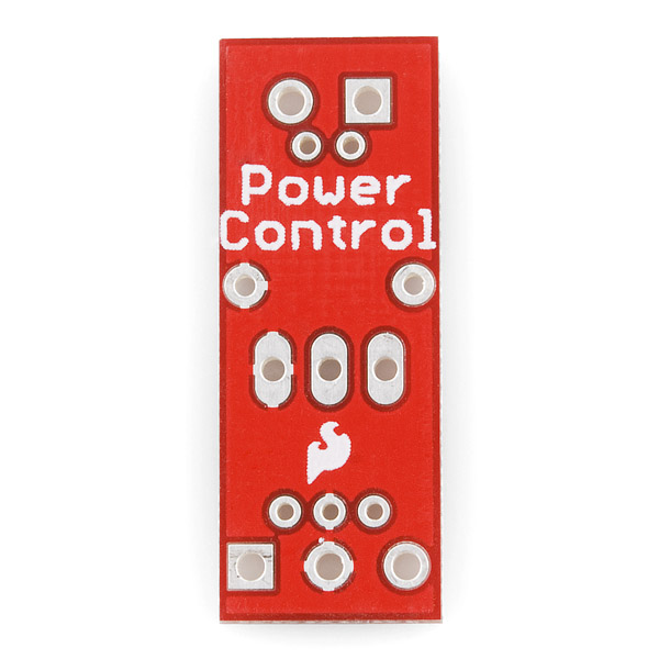
- SparkFun MOSFET Power Control Kit

SparkFun MOSFET Power Control Kit
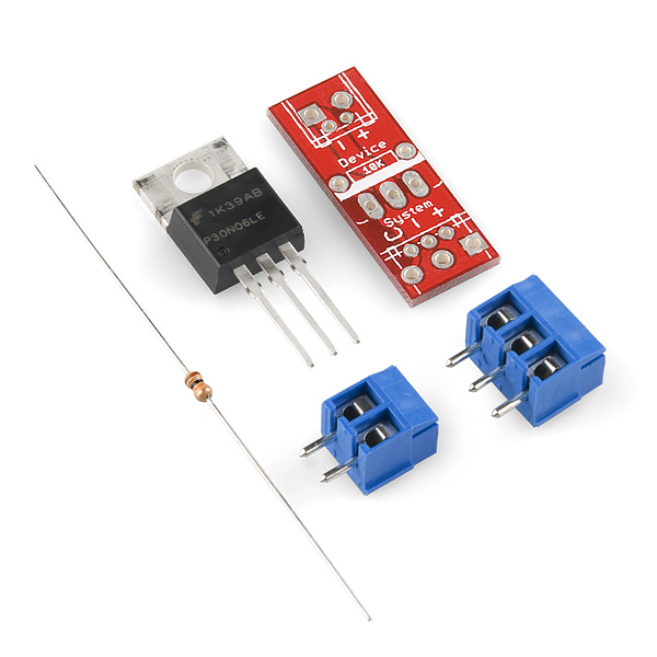
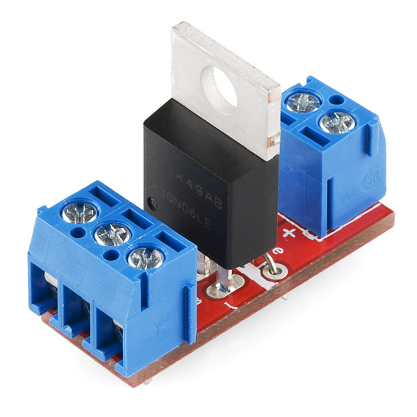
The SparkFun MOSFET Power Control Kit is basically a breakout for a RFP30N06LE MOSFET. We give you terminal blocks for connecting wires in and out of the board and a 10k resistor. If you've wanted to use a MOSFET, but need a better way than your breadboard, check out this little kit.
- 1x - 10k resistor
- 1x - RFP30N06LE MOSFET
- 1x - 2-pin screw terminal
- 1x - 3-pin screw terminal
- 1x - PCB
SparkFun MOSFET Power Control Kit Product Help and Resources
LED Light Bar Hookup
September 24, 2013
A quick overview of SparkFun's LED light bars, and some examples to show how to hook them up.
Core Skill: Soldering
This skill defines how difficult the soldering is on a particular product. It might be a couple simple solder joints, or require special reflow tools.
Skill Level: Rookie - The number of pins increases, and you will have to determine polarity of components and some of the components might be a bit trickier or close together. You might need solder wick or flux.
See all skill levels
Core Skill: Electrical Prototyping
If it requires power, you need to know how much, what all the pins do, and how to hook it up. You may need to reference datasheets, schematics, and know the ins and outs of electronics.
Skill Level: Competent - You will be required to reference a datasheet or schematic to know how to use a component. Your knowledge of a datasheet will only require basic features like power requirements, pinouts, or communications type. Also, you may need a power supply that?s greater than 12V or more than 1A worth of current.
See all skill levels
Comments
Looking for answers to technical questions?
We welcome your comments and suggestions below. However, if you are looking for solutions to technical questions please see our Technical Assistance page.
Customer Reviews
No reviews yet.
Looks great, I wish it had holes for screws, or something to hold it down.
Kudos on needed mounting holes.
You can use MOSFET radiator mount hole
Cool, what does it do? Step-up, step-down, regulate??? Sorry for my noob question.
Edit:
After looking around it appears to be a 'switch'...is that correct?
http://bildr.org/2012/03/rfp30n06le-arduino/
Yes, i guess we can say it is kinda switch :)
The mosfet can handle up to 30 amps with a heatsink. Whats the maximum current the board can handle ?
The trace is 80 mil. Assuming the copper thickness is 1 oz/ft, the board can handle a recommended maximum of 4A.
I give it 5A and no problem till now... But I gave it for a short-time use (10 to 20 sec)!!!!!!! For long-time use I am 4A tops I guess.
This would indeed be good to know!
Can this be used more or less as a drop in replacement for a relay?
I'm thinking fully solid state blinkers (more reliable!) on an old car..
I am using it as an Arduino controlled relay for home automation, and no problem so far... So yes :)
Does this part have an internal diode to protect the FET from inductive kick?
I would like to cite the SparkFun History Museum - Rules to Laying Out a PCB:
"2. Don't forget the standoff holes"
What is back ordered? Just mosfet? Can we order the other parts
I'm using this and an Arduino to control a string of 12V LEDs. When I add power to my setup the LEDs don't shut off completely they're pulling a little bit of current. I have no idea why this is happening. Anyone know what would be causing this?
Thanks Rich
I'd like to use this to control voltage using PWM. Is this appropriate for this application?
I am trying to control a bunch of LEDs from a Raspberry PI board that I would need to flash very fast (about 7000 to 10000 times a second). The combined current for all LEDs is about 2 amps. Does anyone know if I can just take this kit, connect it to my Raspberry PI and connect power and LEDs to it and it would just work? Or would I need to do more. I am very much a beginner at this so any help would be greatly appreciated.
Can I use this breakout to turn on/off a device 110V? Home appliance, computer whatever...
No. You can't generally use a single MOSFET to switch A/C - you'd need two and I don't think this breakout board would be your best bet for it. Note that the included MOSFET is also rated to only 60V.
You would typically be looking at either a classic relay such as in the Beefcake Relay Control Kit, or with a solid state one such as the Solid State Relay Kit.
Thank you!
Extremely disappointed with these. I bought a bunch of them assuming that the smaller pads at each end were spaced 0.1" apart for standard pin headers, but they're spaced much closer together than that and are positively tiny. I was hoping to use a standard servo cable on the input side, plug a motor into the output, and use the spare set of pads on the output that would normally be used for the screw terminal to install a rectifier diode.
My fault for not looking at the eagle files I guess, but from a design standpoint it makes no sense to include a second set of attachment points for wires when there is another slightly larger set of pads right next to them which would work just as well for that purpose.
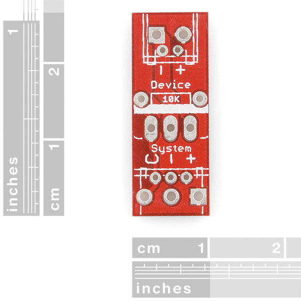
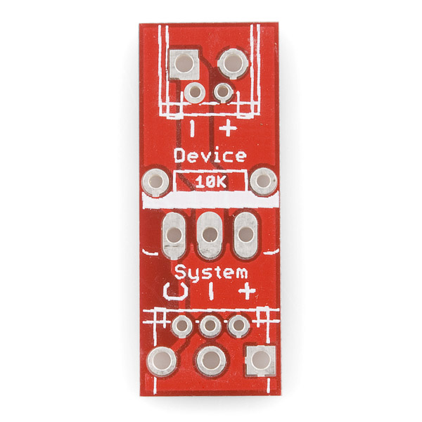
Has anyone ever found that the signs ('+' '-') marked on this board are reversed?? I've burnt 2 Arduino boards due to this!! If you take a careful look, the square hole is aligned with the '+' sign on the 3-pin side, which should actually be '-'. And if you test with a multi-meter, the tow positive hole are connected !!!
Yeah, I was going to get this board, but it's like it's a bit off of what I was going to do. The buildr tutorial they have listed on the MOSFET's page is wired differently than this board does. It's kind of a shame since I wanted the thicker traces.
I am having problems with Arduino UNO and Pro using this MOSFET. I don't know if the problem is for frecuency rate on this boards. Someone knows the answer? By the moment I am using a analogWrite(pin, 100) and the output is 100% of my power suply, there are no changes if I put analogWrite(pin, 100). Thanks in advance
analogwrite values go from 0-255. It's not a percent. Try doing a digitalwrite though. As this will give you max voltage. Since you don't need to specify a voltage, going to the max is best for this scenario. The reason is the mosfet needs a certain amount of voltage to turn on. If you don't reach that voltage it'll do nothing or maybe do something and get hot and fry itself.
Hey all, still have a couple questions about this breakout. Do I still need a capacitor on my DC motor like I do with a TIP120 Darlington? Also, any consensus on weather or not to put the resistor between the gate and PIC like rsp and russpattersun suggest above? If so, there is a big difference between the 150ohm and 10kohm suggested. 150ohm seems a bit small to me... Thoughts?
A version with 4 mosfet inline and some mounting holes would be awesome!!
It would be cool if you sold the breakout without the MOSFET.
Seriously!
Here is a little (lame) circuit diagram for this board. circuit diagram
Thank You, I understand now this is wired up now
Has anyone made a Fritzing part for this?
I've got these doing PWM fading for a big section of the 60 LED/m strip. So, FYI: PWM works fine for fading LEDs that draw a decent amount of current. Though I learned some things in the process.
Since these are "power" control, the labels are "+" and "-", with the control labelled "C". Makes sense, except that I was previously dealing with the mosfet itself which has Gate, Drain, and Source pins. I'm still learning much of the electrical engineering stuff, so it took a bit of time, experimentation, and vulgarity to figure out which pin mapped to which terminal, which I will share:
I have output pin 3 (for PWM) of the Arduino connected to the "C" terminal. This is connected to the Gate pin. I have +12V going to the LED strip's +12V lead. The red LED lead connects to the "-" terminal on the other side of the board opposite of the "C". The "-" terminal there is connected to the Drain pin on the mosfet. I connect the "-" terminal next to the "C" terminal to ground.
So this will only work for switching to ground, unless you have something like an LTC1155 high side driver am i understanding that correctly
This is a N chan. Sounds like you want P.
well with LTC1155 you can run 2 n channels on the high side I believe. I think u need to supply negative voltage to the gate with p channel but not "positive" on that. Pun intended.
Will this give a PWM output if PWM is inputed? Or is only a switch
Yes, it should work like that according to this website. I know you asked this like a year ago, but perhaps someone else may find this helpful.
Could i use this with my Arduino to power this 5v solenoid?
Help need with ground. I hooked this up to s string of six high power LEDs. The V+ and V- from the LED driver went to the device screw terminals. I then hooked up Vin and Vout rom my bench top power supply set to to provide no more than 24volts and 150mA. I wanted to start slow at first. Before attaching my arduino I wanted to test the circuit, but where to get 5v from the trip the MOSFET? I worried maybe incorrectly, that a battery wouldn't share a ground with the power supply so the 5 volts coming from the battery could have look like anything on the C pin.
So I opted to use sparkfun's breadboard power supply stick. I powered ith with a 12v wart from the same plug as the power supply. I rogues with the same ground 5 should be 5 volts. And it seemed like it was for a second, the led lit up but barely. Then POOF the breadboard power supply blew up. Why did this happen ? What did I do wrong?
maybe reading their Unregulated Power Supply Tutorial might help
I assume that the board is designed for the full current and voltage of the MOSFET (MOSFTET)? Or would that assumption result in smoke? ... I'm going to go for it anyway ... you should specify max current for this board and the power shield...
Help. I'm seriously not sure how to wire this up. I'm confused as to the + - markings on both sets of jumpers. Can someone show me this in an example circuit?
To clarify -- can I just put the low voltage 5v power-ground-signal from my arduino board on the "system" jumper and then wire the 'device' side in series with a high voltage, high current car headlamp -- as if the device side was just an on-off switch? Is it that simple? My main question is really whether I need to co-mingle the power supplies... Or whether power from the controller side leaks over to the device side...
Looking at this picture going clockwise starting at the very top left:
* The headlight's negative lead
* The headlight's positive lead
* Your supply voltage (The voltage/current your headlight needs)
* Gnd
* And Arduino IO pin
1 and 4 are connected through the mosfet. Connectivity between those two pins is controlled by 5.
2 and 3 are connected together directly, so they could be omitted.
Penny dropped. Member #132581 diagram helped with the above explanation. Thank You.
Thanks, this was a HUGE HELP! I now understand how this thing works! Thank you!
This thing gets VERY hot. Burned me almost. I put a heatsink on it and it still gets hot. And the heatsink covers the 2 pin screw terminal so whenever I need to attach different wires, I have to remove the heatsink. Works well though. VERY GOOD.
Use PWM instead of analog at the base, you may not even need a heat sink. I would use a Optocoupler to separate the base from the PWM signal pin though.Percautions
so say i am connecting my arduino uno to a lamp to turn it on and off this is a switch or wat like i wanna know how to hook it up and if i got the definition of this thing
I am using this with a picaxe to turn on and off some of the rebel LEDs and a green laser, its working nicely for this purpose.
0.1" pads on the input side would be a nice addition (breadboard, Polarized molex connectors, etc).
A "breakout board" for a 71-cent transistor? Do people not have breadboards anymore? Am I missing something?
I guess I thought breakout boards were for surface-mount parts, or parts that required a ton of support circuitry that's rarely modified?
I understand breadboards have limited current-carrying ability, but those connectors can only accept 20-gauge wire and the transistor lacks a heatsink (or room to mount it), so that's sort of a moot point, isn't it?
funkathustra,
I think your missing the whole point why SparkFun and other have had such great success in the last few years. Breadboards are great if your working on your bench. But once I want to test my project in real-world environments, my breadboard projects usually become intermittent, wires fall out, and I always have a risk of shorting something out.
Break-out boards have allowed me to build many one of a kind complex projects that last for years. A little 3M Command double-stick tape, a handful of break-out boards, interconnected wires with screw terms or solder, and presto! A project thats rugged enough to show a potential customer, colleague, or be embedded in a bigger project. You gotta love it!
And... I wished Sparkfun would come out with this very product for a year!
Breakout boards are mostly meant for avoiding soldering, modulating designs, and prototyping. They are not meant to make entire projects out of.
It would be really cool to see SparkFun carry a board with an IRFP4004PBF or IRF2804S-7PBBF with a decent heat sink for fun projects like Capacitive Spot Welders. :-)
@SparkFun,
It would be helpful if you told us the maximum wire size for the terminals or, at least, which terminals those are so we can go find that datum.
TIA,
Eric
There, how's that?
Very nice kit! Here's a hint for you MOSFET (and MOSFTET) users; don't let the MOSFET gate float. If the gate has a chance that it might float (i.e. it's connected to a PIC output that might not be initialized as an output very quickly), then tie it to ground through an arbitrary high resistance (10K to 1M is fine). This will avoid random high frequency switching of the MOSFET, which can lead to overheating and the "SparkFun" effect (i.e. destruction) pretty quickly.
rsp,
Am I missing something here? It appears this kit has a 10K pull-down on the gate.
Are you suggesting that:
a) If one uses this kit, an additional high impedance path to ground from the gate is necessary or
b) If one uses a MOSFET for this purpose without using this kit, one needs such a pull-down for the gate?
TIA,
Eric
Not so much a pull up, but a current limiter. When you use a mosfet/mosftet with a microprocessor (pic, avr, etc) that resistor helps protect the mcu's pin from excess current.
Learned this the hard way building a stepper motor controller
I concur with SuperFlux. You should have about a 150 Ohm series reistor between the MCU and the gate, it should be as close to the gate as possible on the board layout. As well as protecting your MCU from over-current it will prevent ringing while switching at high frequencies.
The next cool breakout board would have a solder-jumperable high and low-side gate driver.
Also bigger traces for high current.
Great item for a breakout board.
typo... "use a MOSFTET, but ..."
Um,er, no, it's just a NEW type of MOSFET! It's like a super MOSFET. But I guess the world isn't ready for that yet.