- Home
- Power Cell - LiPo Charger/Booster (Old-School)

Power Cell - LiPo Charger/Booster (Old-School)
Replacement:PRT-11231. The new version breaks out the EN and PS pins and also adds a solder jumper to disable the under-voltage lockout. This page is for reference only.
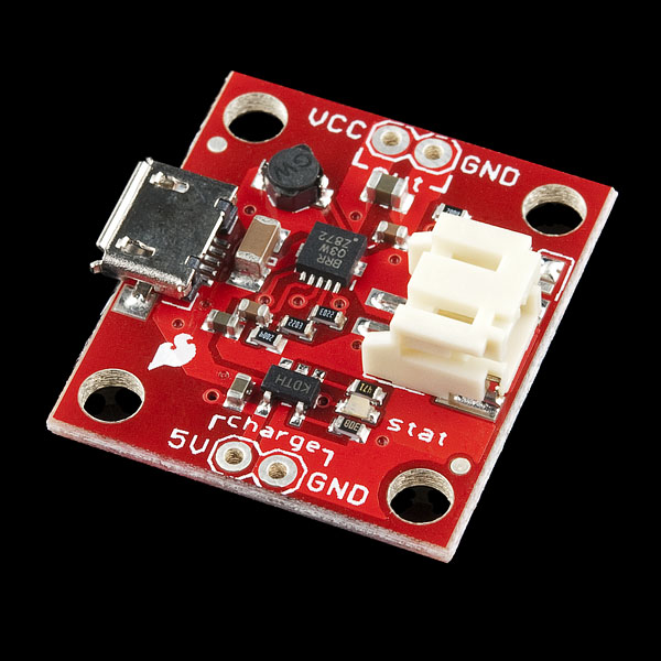
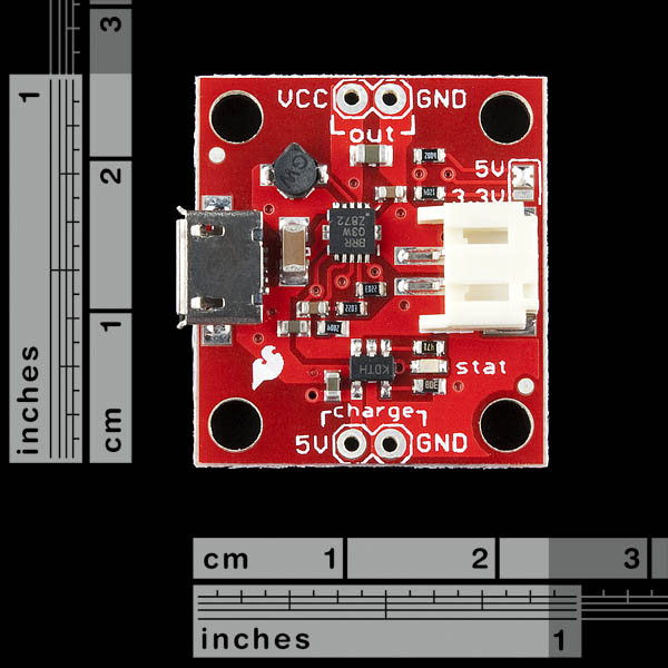
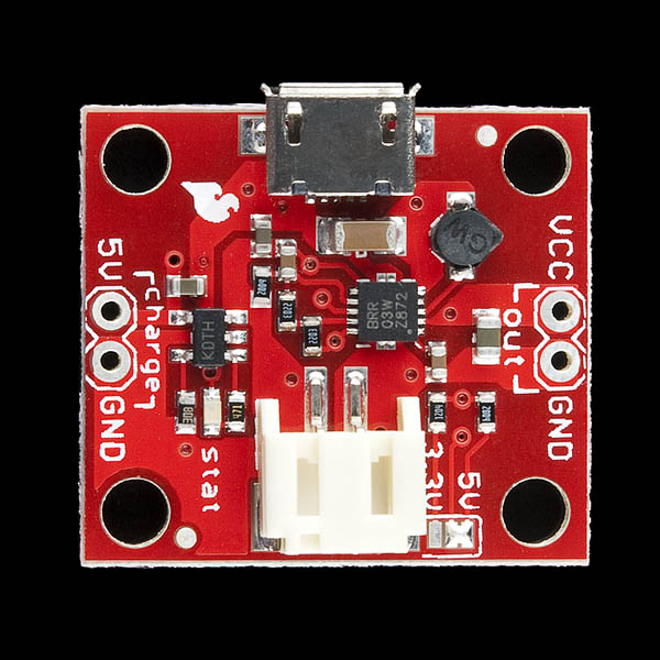
The PowerCell board is a single cell LiPo boost converter (to 3.3V and 5V) and micro-USB charger in one. The board comes with a JST connector for a single cell LiPo battery, a micro-USB connector for the 5V charge input, and selectable 3.3V and 5V ouput pins (labeled 'out'). There are also two charge pins broken out (labeled 'charge'), so you can use another 5V power source to charge the batteries, if you don't have a micro-USB cable .
The micro-USB charger uses the MCP73831 and allows you to charge 3.7V LiPo cells at a rate of 500mA.
The boost converter is based on the TPS61200 from TI and has solder jumper selectable 5V and 3.3V output, and an under voltage protection of 2.6V.
Note: This board does not have reverse polarity protection, so please be sure to recognize the polarity of your connections!
- MCP73831 Single Cell LiPo charger at 500mA
- TPS61200 Boost Converter
- Selectable output voltage 3.3 or 5V
- 5V @ 600mA max
- 3.3V @ 200mA max
- Undervoltage lock out at 2.6V
- Quiescent current, less than 55uA
- JST connector for LiPo battery
- micro-USB connector for charge power source
- Inductor: 4.7uH, 1.2A Sumida CDRH2D18
- Over temperature protection
- Schematic
- Eagle Files
- Datasheet (MCP73831T)
- Datasheet (TPS61200)
Comments
Looking for answers to technical questions?
We welcome your comments and suggestions below. However, if you are looking for solutions to technical questions please see our Technical Assistance page.
Customer Reviews
No reviews yet.
There are some significant limitations to this circuit that should be stated somewhere in the specifications.
First, the Power Cell - LiPo Charger/Booster does NOT enumerate with the USB host to negotiate drawing more than 100mA. Therefore, even though the MCP73831 is setup to deliver 500mA to charge the LiPoly battery, in does not do so. Some USB hosts may actually shut it down for drawing more current than 100mA without going through the proper protocol to request 500mA. If a 200mA load (for example) is connected to the battery while it is being charged, the battery will not charge when the Charger/Booster is connected to USB power.
Second, when battery is drained down to the point where Vout turns off (Vbat < 2.6V), the charger IC (MCP73831) enters a preconditioning mode. When the Power Cell is reconnected to a 5V supply to recharge the batter, the charging current is capped at ~50mA until the battery voltage rises above 3.0V. This means that if the load circuit is still connected to the battery while it is being charged, and the load is drawing more than 50mA, the battery will not recharge.
Third, when the battery drains down further as it remains connected to the Power Cell after Vout has turned off, the battery voltage reaches a point where the Power Cell is not able to recharge the battery at all, even with the load disconnected. However, the battery can be recharged if separately connected to a USB LiPoly Charger (PRT-10161) powered from an external 5V supply.
Thank you!
I completely agree, these are really important issues that need to be documented. This preconditioning of the battery has been driving me nuts! I've had this problem for ages, once the battery drains, it becomes impossible to recharge the battery again without disconnecting the load or the battery. When the battery gets to the level you mentioned in your 3rd point, it seems that connecting it to a power supply will not do anything at all apart from make the MCP73831 emit a high pitch whistle - no charging.
Have you got any suggestions about how the board could be adjusted to avoid these problems, so that it could be embedded into a project?
I would like to know this as well... This is going to be embedded in a permanent enclosure to act as a UPS System so when power goes out it'll have a battery backup. I don't want it to not be able to charge the battery, and my circuit will draw aprox. 200mA.
SF Guys, this is important!
You should really consider disconnecting the PS pin on the TPS61200 on the next run. The way you configured it currently power save mode is disabled. This means the switcher is operating at full frequency, even when no load is connected. This results in terrible efficiencies when no load is connected. The way this board is designed currently it WILL drain a battery within a week or so. I measured ~10mA draw from the battery when testing with no load on a circuit I implemented using these parts.
This makes the product almost useless for data loggers and the such. Cutting the PS trace dropped idle power consumption down to a microamp or so, where it should be!
Agree, this board drains the battery big time! I have a 240mAh battery that was left connected to this board with no draw from the circuit (switched off). The battery was beyond dead the next morning.
I'm 100% with you dude, do not know how they could overlook such an important issue
For vNext, could you use the MCP73871 instead. Has auto switch between vbat and usb and will charge vbat at same time as running Sys from usb.
I think there is one thing missing on this breakout board. A coulomb counter, or equivalent, something like the DS2745 which allows the host micro controller to keep track of the battery level e.g. fuel gauge.
Would allow the folks who are interfacing with a micro to know when the battery is low and needs charging. via display, flashing led, etc.
my two cents.
Feed the positive battery terminal into an analog input on the arduino, have it start charging at maybe 3V.
battery + -> 100k resistor -> Arduino analog pin works perfectly
see http://i.imgur.com/OgQjl.png
What is the "y = x/204.6;" calculation for? Does this have to do with the 100k resistor?
Edit: Nevermind, i figured it out.
Can I have Vout (5 or 3.3 Volts), while battery is charging? When I disconnect the USB cable or charge terminal, can the battery support Vout? I mean, Can this board works like a No-Break?
i'd really like to know this also.
Hello!
So i have this little circuit board and it is so neat! To answer your question the charging circuit and the boost circuit are independent which means you can charge the battery while supplying something with 5 or 3.3 volts. I am not sure what a No-Break is but this circuit board will give a constant 5 or 3.3 volts as long as your lipo battery is above 2.6 volts and you can charge it whenever you would like and it does not affect the output.
SparkFun: PLEASE READ THIS!
1 - The PS (Power Save) Pin (TPS61200) should be set by a solder jumper so the user can enable or disable it as needed.
2 - Please breakout the + Battery Pin, or find another way to monitor battery life via a Micro-Controller!
3 - Set a safer "Undervoltage lockout". Probably to 2.75 Volts as stated in LiPo Batteries Datasheet.
4 - When battery is drained down to the point where Vout turns off (Vbat < 2.6V), the charger IC (MCP73831) enters a preconditioning mode. When the Power Cell is reconnected to a 5V supply to recharge the battery, the charging current is capped at ~50mA until the battery voltage rises above 3.0V. This means that if the load circuit is still connected to the battery while it is being charged, and the load is drawing more than 50mA, the battery will not recharge. --- Please Find A Fix For This!
In 5v mode with a 3.7v cell (the Union 110mah pack to be exact), it draws 7 milliamps with no load! That's less than a days life out of that particular pack.
Switching to 3.3v mode, the unloaded current draw is 70 microamps, or ~2 months of life. The reason for this, I believe is the PS (power save) feature. The datasheet explicitly mentions that in down convert mode PS is enabled, despite being disabled by virtue of this board design.
It seems to imply that if you can, run at 3.3 volts. If you have very steady hands, it should be possible to cut the trace to PS and green-wire it to GND.
It would also be nice if the PS pin were select-able the same way voltage is.
I agree that the PS Pin should be set by a solder jumper!
Sparkfun, Please do this?
5V @ 600 AMPS ????!!! wow, this thing is great :-)
I'm surprised nobody caught this yet. I don't think the TPS61200 is quite good for 600 amps...
Also, I second the suggestion to add a coulomb counter/fuel gauge chip to the mix.
A USB connector,and a few resistors would give you a MintyBoost SR. or would it be SuperMintyBoost?
The inductor on the schematic doesn't match the one on the webpage. Which is correct?
Also, I don't suppose SF has plans to make a boost converter with >1A output? Those LiPo batteries can support constant discharge rates of ~10-20C (at least 10A), so it would be nice to have an alternative (external switch?) that could support more current.
finally the one obstacle preventing me from switching to LiPos is gone.
a LiPo charger that is small and capable to output 5v sounds perfect.
altough i don't really like the microUSB socket, but thats just because ive never used any and don't have any usable cables for it.
ok
I want to use this unit with a solar cell input what is the functional input range??
Check the datasheet for the MCP73831 chip on the charger. The absolute maximum input is 7V, and the minimum needs to be above the lipo's "full" voltage of 4.2V.
Regarding running this off a solar panel, I've put more in the comment here.
I have a cell who's spec is Open Circuit Voltage: 7.0V Peak Voltage *: 6.0V Peak Current *: 566 mA Peak Watt.: 3.4 Watts Will I need protection and if so what kind?? Brad :) an old friend
Hi, about 7 months ago I wrote a comment. I thought a couple of battery chargers had burned because after a few days of use, the 5v output of the booster was at zero, even though the battery voltage was at 3.7 v (in fact I had hardly used battery power). I noticed that, despite this, when you connect the charger to a USB port, the battery was still in charge as the red light was still on. After a few minutes booster output rose again to 5v and I turn on my device, the battery voltage continued to increase at a slow pace, and after 36 hours it was barely 3.95 v, far from the 4.2 v. I decided to disconnect the charger from the USB port, fearing that the battery is damaged, could someone explain how it is that the charge cycle is so slow in this case? Thanks in advance ...
Will this board shut off when the LiPO is charged?One more thing, can I use this board as a in energy harvesting applications like sparkfun's "LiPower - Boost Converter"?
Can I over charge a LiPo battery with this board?
Hi, I'm using a board with the IC MCP73831, when connected to USB port only thing it does is light the LED every 30 seconds, also if you connect the battery. the supply current is minimal, we note that not charging. know what that means?. thank you very much.
The Features section indicates 5V @ 600mA capability, but this board does not appear to be able to supply the necessary current to power a 5V @ 220mA device that I've wired up to the OUT VCC and GND. Am I misunderstanding something?
Hello, I need to get 3.3V AND 5V. Is there a way to "hack" the board at the jumper level to get both of voltage? any ideas?
Thank you
You won't be able to have 3.3V and 5V out, at the same time, with only a battery connected. If you have USB plugged in, you can have 3.3V on the output and then tap the USB VCC (5V) off of JP9 (see schematic)
I is only with a battery connected. So I would need a second TPS61200 boost converter like in the PRT-10255 board to get 5v?
Just a heads up, the Micro-USB port on these is -very- fragile. Double check the two mounting tabs to ensure that they've been soldered on properly. I've had two jacks tear clean off the boards recently due to cold solder joints (or not even being in contact with the board in one case). Also, the mounting pads aren't linked to anything (like the ground plane) so they can de-laminate from the board substrate quite easily. A dab of epoxy around the footprint of the connector should anchor it solidly, and prevent you from having to resort to hand soldering the jack back down.
I would love to have something like this with two modifications: 1) Allow me to set the output voltage via jumper OR by using a trim pot, so I could have, say 6V, which is good for servos. 2) Break out the rest of the USB so I can pass it to a USB to SERIAL converter.
What does it mean when the charge indicator is flickering? I have the battery anode connected to a 100k resistor which is connected to A6 on my arduino but the arduino is not connected to power. The battery voltage reads 4.1V
Something isn't right if the LED flickers. Try simplifying your setup and see if the board does it with only a battery and USB connected. If it does, please contact techsupport at sparkfun dot com since you may have a faulty board.
The MCP73831T datasheet states that it supports both Li-Ion and Li-Poly cells. Has anyone tested/tried the booster/charger board with a Li-Ion cell?
Ok, I have confirmation that this booster/charger will work with Li-Ion 3.6v cells. I have charged and discharged 18650's (or similar, 2600mAh) several times. I have also got it to work with one cell and two cells (in parallel, initially charged and connected to each other to level off; Be careful when hooking up cells in parallel and charging them!!
My only problem with this board is the micro-USB connector. The connector is 'tight' and requires quite a bit of force to get a connector in and out. I found out the hard way how much force the connector can take before BREAKING OFF THE BOARD! Needless to say I was not pleased, but was able to re-purpose the board and use the second one I had bought.
Sparkfun: Please develop a similar board that has a mini-USB connector and maybe something that will charge 4 cells? :-)
Pharoah, are you using 18650's that are individually protected, or unprotected?
Unprotected. These were pulls from laptop battery packs. I just weeded out the bad cells and added connectors, instant project batteries. The cells are not used in anything that does not have a current limiter and low voltage protector.
I have a 110mAh battery and this thing has the red LED still on after a couple of hours (though the LED seems to be flashing).
If this charges at 500mAh shouldn't my battery be charged in 10-15minutes?
It's this battery that I have: http://www.sparkfun.com/products/731
It should be noted that I have two of these chargers, and two batteries and the other one seems to charge just fine.
read earlier in the comments. If your cell is discharged too much, it will do a preconditioning charge at 50mAH.
Confused the schematic shows no connector for the VBATT line on the TPS61200.
The schematic shows JP2, JP9, USB, JP12, and JP1 (5 connectors). In the photo I see USB, a LiPo connector, Vcc/GND, and 5V/GND (4 connectors). I am guessing the the LiPo connector is JP1 or JP12. The USB is USB and Vcc/GND is JP2 and 5V/GND.
Will this power an ArduiMU+ ? (http://www.sparkfun.com/products/9956). In the comments it says that you can use either a Power Cell or LiPower to boost it up, but this says it only goes up to 5v (ArduiMU says it needs 6v...)
Can I cut the trace for the PS pin to get powersave mode or do I need to add a pull-down resistor?
Is the output on this thing current-limited, or will the magic smoke come out if i accidentally go over 600mA?
Hi,
there is a led on the board which is the color code?
thx
Hello
does anyone know what I am doing wrong? I dont know if i didn't read the data sheet correctly but I have hooked up a 4000 ma battery to this little board and after draning it down to 2.8 V it cuts off (instead at the 2.6V UVLO) and when I charge it, it only goes up to 4 V (instead of the 4.2 V)
Thanks all!
Are you sure you're using the right battery with it? A LiPo should be 3.7V (per cell), which this circuit is specifically designed for.
The micro-USB connector just broke off of my unit. My fault, but it didn't require much force at all. If you're a little heavy handed like me, I'd recommend a little epoxy to strengthen the connector.
Good to know. I just broke the micro-USB connector off of my first one about a week ago.
HOWEVER, it appears that the circuit still works if you feed in a regulated 5V to the Charge connectors. I ordered a new one so i could still have a project with micro-USB charging, but the broken one will still be used in other projects connected up to a 5V regulator (with caps) and barrel connector.
I bought this with a 3.7 LiPo (PRT-08483), so that I can get 5V for my arduino and also to charge the LiPo when needed via microUSB.
* How do I know when to charge the device? There's no feedback for the arduino to indicate that the battery is low, is the idea that when the device no longer powers up, it should be charged?
* Is there any indication on whether the battery is charging or not?
Basically, I'm wondering, do I need something like the AttoPilot Voltage and Current Sense Breakout device to monitor and provide feedback on how much power is left?
Thanks in advance
You can cheat, sort of. Because since the resistance of the LiPo will stay about the same, if current drops, voltage drops, too. Just feed the + terminal into an analog input on your arduino, and your will have a low-batt detector.
huh... that's an interesting suggestion, baum. I'll give that a try - thanks!
I'm planning on using this with one of your solar cells - which will not be able to reliably supply 500ma to the board. Will this present a problem?
Shouldn't be a problem
the 500ma is the maximum, if I am correct.
the lower your mA, the slower your batteries will charge. What does your panel output?
I'm missing something. 3.3v at 200 mA, "calculated", but then how can it do 5V @ 600 mA? The efficiency isn't that much different and I don't see how it can do 3 watts at 5v but only 0.66 watts at 3.3.
Can this thing be used on a switch to switch the battery between this charger and a load circuit without burning my landlords house down?
Please, the same but with mini-USB connector
I also think that a "fuel gauge" feature would be nice, either in a bargraph display or a red/orange/green (with a bicolor LED) display.
One other thing that would be nice would be a "pass-through" feature, so that you could charge the battery while a load is connected (and bypass the boost converter).
MCP73871 IC (suggested earlier by williams) would allow you to do load sharing, and it has support for a low battery indicator.
I do not understand where the 200mA at 3.3v limit is coming from. The data sheet lists this as the maximum efficiency point for 3.3v but does not list it as the maximum current draw. Can anyone enlighten me as to why this limit is there?
It is roughly based on the thermal properties of the layout and specific parts being used (i.e. the inductor). It is by no means set in stone and I would bet you can run it a little higher, however that depends on what your application requires.
I hoped to run an xbee pro from this in a hand held remote. the listed tx power required is 200ma, with a few leds I would pull at most 240ma, but the xbee would not be transmitting continuously either. Maybe 2 to 4 times a second, just a few bytes that read one of the analog input pins.
Is there an easy way to get the actual input voltage of the lipo?
I want to measure the voltage and light an LED if it drops too low to inform that it needs to be charged.
I considered cutting the cables of the battery, but if there's another way it would be nice.
Question: I have used this product to drive a PCB design and it worked perfectly. Now, I tried to implement the same design onto that same PCB, only my circuit emits a high-pitched buzz. I know it's not really your department to help others with their designs, but does anyone have any ideas? I hand-soldered the chip myself, so I could be a poor solder point...
10Q
I already have two of these but if you add a fuel gauge to it I will happily buy more just so I don't have to hack your board up :)
Do you have a timeline as to when these will be back in stock? Thanks.
YAY! New stock!
Yeah! come one please!!! Are you coming out with a new one or something ?
Need this for Space Invaders Arduino!! When will it be back? Rev up that pick-n-place! ;)
I just got this delivered, after ordering it on the weekend before it sold out. I'm documenting it up on a flickr photo of my project, which now has seen a reduction in the number of boards and cords I'm using. I now need to put in a switch and make a case for it and the LiPo battery, but only if it lasts for 16 hours! 6 Ah battery should go the distance.
WHY does this kill my battery when nothing is connected to the output?
The lipo battery held a charge for 4 months with nothing connected to it - i plug it into this board, re-charge it up - and a week later the battery is at 2.2 VOLTS ? ..with NOTHING hooked up?
....hope my battery isn't killed
Can I desolder the micro-USB connector and solder on a Mini-B plug (5-pin) connector in place? Will it work??
You guys should look at the application note AN1149 from Microchip and implement something similar on your lipo charger that have a system output.
The way I see it now, the current used by the system is current that should be used to charge the battery and given that Lipo are charged with a constant current, that has to be messing with the charger.
The suggestion to include some way of turning on the system load is very applicable as well!
+1 for providing 3.3V or 5V output.
I might be missing something, but is there a way to turn this thing off short of disconnecting the battery? I.e. if I was creating a battery-powered device, would the power regulator continue to operate and drain the battery even if nothing was drawing power through the output terminals?
Thanks!
Whoa, Who can complain about that power output!
"5V @ 600A max"
Who needs 1 measly amp when this does 600!
:p Love the typo guys, was that seriously to correct another mistake?!
Also, why didnt you launch this BEFORE I spent my Freeday coupon!
one question: if i use this to power an atmega 328 at 3.3v, would i need an additional voltage regulator / capacitor etc or is all that now covered on this board? thanks, ben
600A? That's quite impressive :)
Great board and It would be great if you could break out "EN" pin
Isn't 2.6V too low for a lipo low voltage cutoff?
It should be pointed out that this is a boost converter and will not properly put out 3.3V unless the input voltage is below the output voltage. A buck-boost converter like the TPS63000 would have been a better choice here.
It's more than just a buck converter, it has a down conversion mode which regulates properly when the input voltage is higher than the desired output, albeit at a reduced efficiency.
From the datasheet:
"If the input voltage reaches or exceeds the output voltage, the converter automatically changes to a Down Conversion mode. In this mode, the control circuit changes the behavior of the two rectifying switches. While continuing switching it sets the voltage drop across the rectifying switches as high as needed to regulate the output voltage"
Yep, exactly right. The TPS61200 works just fine for most applications converting the entire LiPo battery voltage range (2.6-4.2V) to down to 3.3V. See Figure 8 on page 8 in the datasheet.
Dayblur, nice catch I was basing my findings on the TPS 61030 that did not have this feature.
Agreed!
The TPS61200 datasheet only rates this @600mA for 5V out. Are you sure it can output up to 1A?
I think the pin-outs are the same, can we part-swap in a TPS63000? (i void warranties!)
One last thing, you guys should sell this with a LiPo like you do the charger.
edit: The footprints ARE different. No part-swapping here! :(
did you switch it out for the 630000? I took a quick look, and it looks to be the exact same thing, save for a higher output capacity
nope, nevermind
Q. Can the charge voltage be 5-7v like the usb lipo chargers?
Rocksome! I've cobbled together a couple versions of this and would much rather just buy one prefab. This looks like it does exactly what I want for almost any battery-powered electronic device - thanks.
Nitpick: Check the units in "500mA per hour". I am pretty sure you mean 500mA, or 500mAh/h, which is equivalent.
Which batteries work with this?
Oh, that is perfect timing for me. Just what I need for my project. I was going to just use two separate BOBs but this is much better for me. Great to see!
It appears that if you jumper the 5V Boost output to the VCC input you could charge USB devices from a LiPo cell.
Or maybe not so easily. You'd need to be able to disconnect the LiPo charger section or else you'd be on your way to discovering electronic perpetual motion!
Yea, no more chopping up the prototyping boards to power my breadboard :)
How about selling a small micro -- mini adapter for use with mini-usb cables? No one wants to carry extra cables around...
Honestly, my experience with the PRT-10300 has not been positive. The first one I bought broke after a couple of days of use, leaving me baffled. Then I bought 2 more and same thing happened with one of them. After analyzing the circuit design came to the same conclusion that Andrew500, the pin on the TPS61200 must be grounded. Otherwise, the booster will still working even if there is load current (whenever the battery is connected and has some power). This is the reason that the batteries are discharged prematurely, or worse, the modules are damaged, as in my case. I must modify my circuit's layout to overcome this issue, increasing significatively their complexity. My experience with you has been generally good, but I feel compelled to make this constructive criticism for the sake of you and the consumers. Thanks from now.