- Home
- Product Categories
- Development Tools
- SI4735 AM & FM Receiver Shield

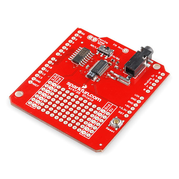
SI4735 AM & FM Receiver Shield
Replacement: None. Unfortunately the Si4735 has been discontinued. This page is for reference only.
The Si4735 is the first digital CMOS AM/FM radio receiver IC that integrates the complete tuner function from antenna input to audio output. This feature-rich solution includes advanced seek algorithms, soft mute, auto-calibrated digital tuning, and FM stereo processing. The chip also incorporates a digital processor for the European Radio Data System (RDS) and the North American Radio Broadcast Data System (RBDS), including all required symbol decoding, block synchronization, error detection, and error correction functions. Basically it's an entire AM/FM, LW/SW radio in a single chip.
Now that we've mounted it on a shield, you can harness all of that sweet radio-playing power right from your Arduino. Simply stack the shield onto your Arduino board, plug in some speakers (headphones don't seem to work as well without a preamp) and use the library below to control the volume, channel selection, etc. The library also allows you to send a variety of other commands constructed by consulting the Si4735 Programmers Guide.
This board seems to get decent reception compared to other stereos around the office even using a simple wire antenna. If you happen to have an antenna that you'd like to use it can be soldered right to the via marked "antenna".
- [Schematic ](http://cdn.sparkfun.com/datasheets/Dev/Arduino/Shields/SI4735 Shield-v12.pdf)
- [Eagle Files](http://cdn.sparkfun.com/datasheets/Dev/Arduino/Shields/SI4735 Shield-v12.zip)
- [Datasheet](http://cdn.sparkfun.com/datasheets/Dev/Arduino/Shields/Si4735 Datasheet.pdf)
- Arduino Library
- [Programming Guide](http://cdn.sparkfun.com/datasheets/Dev/Arduino/Shields/Si4735 Programming Guide.pdf)
- [RBDS Standard](http://cdn.sparkfun.com/datasheets/Dev/Arduino/Shields/RBDS Standard.pdf)
- GitHub
Comments
Looking for answers to technical questions?
We welcome your comments and suggestions below. However, if you are looking for solutions to technical questions please see our Technical Assistance page.
Customer Reviews
No reviews yet.
Been waiting for a breakout for this chip since you started carrying it and it's an Arduino shield?!? Come on, make it a simple breakout so I can use it easily with anything...
Plus oned! This NEEDS to be a non-shield breakout for us non-duino non-conformists :P
Better still, a breadboardable DIP package akin to a Basic Stamp or Arduino Pro Mini.
you could just use it as a breakout board, just use the offset headers and a bread board
The package is a standard 24pin SSOP, sparkfun carries a 28pin variant that should work with it. http://www.sparkfun.com/products/500
No it is not, it is a QSOP, 0.635" pitch!!
Incorrect. The product you point out is for a much bigger IC than the package Sparkfun sells the SI4735 in. Read about people's experience with the BOB-00500 here: http://www.sparkfun.com/products/10227
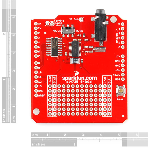
Edit: Look at the size of the center IC on this shield. That is the SI4735. Look at the chip above and left of that. That is an SSOP size.
I thought something like this was about to hit. I would have liked to have had a simple (and cheaper) breakout board but this is great! Thanks SparkFun!
For those who might be interested, I am releasing my version of the Si4735 library. I have put a great amount of effort into this library and spent over a year intermittently working on it. I believe it to be better then other versions out there. I especially improved RDS and RBDS support.
Project Files
Features and improvements include:
I have included a sample program that lets you control the radio and display RDS/RBDS info with serial port based terminal software such as Putty. This eliminates the need for an LCD.
I have also included advice in the README file on successfully level shifting between 5 and 3.3 Volts and how to correct the many defects in the Arduino shield, including the not well known AM receive bug.
Finally, I have included a document I wrote summarizing everything I have learned about RDS and RBDS. This should be a good place to start for others who want to learn how RDS and RBDS works.
If you worked with previous versions of the library released by Jon Carrier, then you know it would easily crash or malfunction when you started to add more stuff to your program. This is because his library was using most of the available RAM. By storing string constants in flash ROM only, the consumption of RAM by the library has been drastically reduced to about 150 bytes. (Future versions may increase this a little.)
By the way, Jon Carrier's library can trigger the infamous "!!!" bug on the Mega 2560. The bug is triggered whenever a program contains three "!" in a row. All Mega 2560s made to-date have this bug. The symptom is multiple timeout messages when uploading your sketch, but it never gives up. To fix Jon Carrier's library, edit the "Si4735.cpp" file and search for: " !!!ALERT!!! ", and change it to: " ALERT! ALERT! ",
To whom it may concern,
I have taken the liberty of forking J. Carrier's code and refactoring it to eliminate all problems caused by (at least) not following the data sheet accurately enough. The resulting code is on github and I have tested it with the Si4735 Breakout Board connected to both an Arduino Uno R3 (using level converters and an Arduino Pro Mini 328/3.3V/8MHz (directly).
It works without any problem or glitch -- please feel free to check it out and prove me wrong on this one :-) I will be more than happy to iron out any remaining bugs.
I have also refactored and enhanced the two examples that shipped with the initial library, I hope you will find those useful and verbose enough to get a good feeling current version of the library. I plan to also implement I2C mode and further refine the RDS/RDBS code to include a full-standard decoder.
In the hope you'll find it useful, @Dexter
Many thanks for your library! It worked right from start like a charm. Using the receiver shield with OLIMEXINO-328 switched to 3.3V Cut pins 2 & 10 of the converter and connected pads 1->2 and 9->10.
You're very welcome :-) It's encouraging to see the sleepless nights I spent reading the datasheet and fixing the library did not go to waste. Also, I'm happy to hear news from another Olimex fan :D
Good luck, @Dexter
Working with the Duemilanove, the library does not return from waitForInterrupt. It could be an isolated case (just me), but I haven't been able to get it to work. I'll contact you over email.
1000USD question: how's your GPO1 line? :-) If it's still tied directly to MISO as on the shield, it's not going to work. See the README of the library.
Definitely user-error. No level converter to drop to the 3.3v. I assumed it would use the 3.3v pin on the card. Bleh!
But your library rocks! Sparkfun should test a version and change the library link on the product page to use yours.
Very impressive work and many thanks for your much needed contribution!
Here is a student project using mbed with this shield
Video demo of radio on You Tube
more info at http://mbed.org/users/bwilson30/notebook/si4735-digital-amfm-radio-receiver/
It was also hacked to use I2C instead of SPI on a breadboard
anyone can explain what the hell is happening that ALL my arduino analog pins read 1023 when using this shield? It works perfectly removing the shield.
I've had this same problem (Arduino's analogRead reading only 1023's). And I did not modify anything to the hardware.
I found the solution when I noticed that the AREF pen on this shield was directly connected to GND. So my solution was to cut the wire (pen) that runs from the shield's AREF to the Arduino's AREF.
After I cut that wire I can read all analog inputs. And that is great because I can now use analog potmeters etc. for frequency/volume changes.
I use analogReference(DEFAULT) in my setup(), but maybe this is not necessary.
Seconded. Spent about a week looking for the 1023 ADC problem.
you're a genius! and fail #2 on this shield from sparkfun!
Is it something in your code? The schematic has all the analog pins disconnected. I don't know if the schematic matches the eagle files though.
Try removing the shield and rechecking the analog pins. If they still read 1023 then it has to be something in your code.
I already checked without the shield and works perfectly.
Even the "AnalogInOutSerial" example using arduino IDE didn't work with this shield connected. Just removing it and plugging the pot directly to arduino made it work.
I don't know if I short something when I cut the GPIO1 trace to add the diode.
Has anyone had trouble getting any sound out? I have to pull the speaker plug out just a bit to get anything! I can only get sound by connecting to the right and left pins, not ground. And yes, I am using an amp.
It worked fine for us. What cable are you using? It sounds like you're using an amp with a floating ground or something...
I'm using a simple set of portable speakers and amp that is used with an mp3 player. I have also used headphones. I know above it says that they don't work well without a preamp. If I connect the left and right out via wires to the headphone plug or the amp plugs ground and left or right leads, I get sound. If I try to use the ground from the headphone jack and then the left or right, silence. I checked that the ground on the jack went to ground and that the left and right out went to their proper places on the chip and they do. At the moment, I am at a loss.
Ok, after trying 2 more amps, it seems to be working properly. Now if I can only get the getFrequency function working. Thanks Robert!
If you look in the actual library file (I think it's Si4735.cpp) you'll notice that the getFrequency function is...blank. It doesn't work yet. If someone can get some code working to return the frequency please post it and I'll add it to the library.
Hi, I think i found the solution to the timing problem. Insert a "delay(1)" after the "spiTransfer(0xE0);" command. This takes the "bus turnaround time" into account (fig. 7 datasheet) and suddenly all long responses make sense.
A delay does help but the problem comes when you want to get the freq after a seek that is taking awhile. The seek comes back with the freq it is currently at, not what it stops on. This is because the seek has not finished. You need to be able to wait on the STC interrupt to be set. That is where I am having problems. I have a temp way around it. The freq status command returns a valid freq flag. I wait until that is set before I consider the info good. The problem with this approach is that if I manualy tune to a channel the reception may not be good and the freq would not be considered "valid".
Your are right, the delay helped but didn't solve the problem... I am also stuck at the STC interrupt. What confuses me is that the STC interrupt comes about 20 ms too soon. It should come after 60ms but comes after ~40ms. I'dont know, it's quite strange... I think there is a fundamental problem with the timing. I hope I have time to hook it up to the logic analyzer tomorrow at work.
I was able to get the STC interrupt to work by using the attachInterrupt(0, intProc, LOW) function. It seems this has to go in program and not the library. In my intProc function, I call the get-int-status function and set a global variable if the STCINT bit is set.
I'm making some tests here. Using SerialExample sketch, if you power down (0x11) and than turn on again(01505) before making any tune, you get reliable responses(I'm using 0x10 GETREV command). When you TUNE to any station you start getting weird errors.
I opened a forum thread here on sparkfun, maybe we can discuss that there.
http://forum.sparkfun.com/viewtopic.php?f=14&t=29114
I found this post on the Arduino site that may shed some light on this:
http://arduino.cc/forum/index.php?topic=66554.0
Reading this makes me wonder if maybe Sparkfun developed the board with the Arduino Pro 3.3v/8MHz but didn't test it with 5v Arduinos. I'm finding that my Arduino Uno displays the same sort of symptoms described in the post on the Arduino site.
I think I'm going to test the shield with my LeafLabs Maple, which runs at 3.3v, and see if that makes it work better.
this make sense. MISO pin is 3.3v out from shield and arduino expects 5v.
Hi, I can confirm that this workaround works!
works for me too!
Doesn't work for me. The diode pulls the voltage up to 3.6 volts, but I still get nothing but 80 and 80 0 0 0 0 0 0 0 0 0 .... when I use the serial example sketch and enter the commands in the comments.
I found YET another problem, the SPI is set by default to it's max speed of 4MHz. This was resulting in some nonsensical responses. I slowed it down to the slowest, 250KHz by setting the SPR1 SPR0 bits in SPCR.
+1 wanting a read function that simple works
Thats right, it is blank. I now have it returning the frequency but my timing bites. If I get it working properly before someone else does, I'll post what I've got.
This breakout doesn't connect the pins for DST output. Echoing what others have said, it would be nice to have a breakout that DOES exploit all the features of this chip, and not limit the breakout pin layout to a proprietary MCU support system. I want this breakout for the antenna support circuitry, the clock, etc. I want to drive it with a PIC. I also want access to the digital audio. I hope something that supports those needs comes soon.
Is it possible to configure the SW/LW output through the DAC left/right to be quadrature (I/Q) instead of demodulated as AM?
Doubtful. I haven't seen anything about I/Q output in the chip's datasheet. That's the down side of having an entire radio on a single chip.
Is there a plan for another radio module? I'm looking for a radio shield and only find this one, which in not longer available. :-(
Hey guys
I am using an arduino uno, the shield, the example sketch and a standard pair of headphones, but I'm unable to get any kind of audio out.... not even static.
I have read that there are several problems with this product and that there are a few modifications you can do to get around these problems, but I've also read that you should at least be able to tune in some stations and get some sound out of it using the basic setup.
Anybody have any ideas? I'm not even sure how to start debugging this
Can I make the SI4735 AM working at 27MHz? The upper limmit according to the datasheet is 26.1MHz.
Can I make the SI4735 AM working at 27MHz? The upper limmit according to the datasheet is 26.1MHz.
Hey SparkFun, the item description above says that "the Si4735 has been discontinued" which is false. -C40 has entered NRND status and -D60 is its replacement.
Ever experienced getting a flimsy sound in FM mode (and only in a certain position of the plug in the phone jack - easily leading to blaming the jack) and no sound at all in AM mode? OK, here you go: Since there are no output capacitors for R&L outputs provided on board and if the amplifier used has no input capacitors, as I experienced with my boom box, the DC offset on the outputs of the Si4735 is responsible for the effect described above. A capacitor of some 10µ each between Si4735 and amplifier will solve this issue. This hint may be of some use for the breakout board as well.
With reference to questions posed by a couple of other posters, I did get this to work with a Mega by re-routing the pins (10 to 53, 11 to 51, 12 to 50, 13 to 52) and changing the appropriate lines in the header file to reflect the new pin numbers. Still not getting good status and response data, even with the diode mod, but the radio receives and responds to commands properly.
Hey is it possible to write the data coming off the FM reciever to a file that can be listened to later?
I am new to arduino/shields/processing and am having compiling errors when I try to verify the sample code provided by Sparkfun. These are the errors:
Si4735_Example.cpp: In function 'void setup()': Si4735_Example.pde:-1: error: 'FM' was not declared in this scope Si4735_Example.pde:-1: error: 'class Si4735' has no member named 'tuneFrequency' Si4735_Example.cpp: In function 'void loop()': Si4735_Example.pde:-1: error: 'class Si4735' has no member named 'unmute'
I have tried to sift through all of the comments, but I am sort of lost. I also do not know if I need to alter the radio shield with the diode conversion? I have a new arduino SMD and it seems that it is provided 3.3V to the shield. Thanks in advance for your help.
The code issues sound like your libraries are not installed correctly in the Arduino IDE. You could also try compiling the code in an older version of the IDE. This might be a 1.0 incompatibility issue.
please delete - double post
After several days of trying to get this thing to work using SPI on my GHI FEZ board (.NET Arduino clone) I was about ready to give up and just throw the board in my junk box. The I ran across the comment by "Member #226770" discussing using the i2c interface. So with nothing to lose I hacked my board to use I2C and bingo it worked. So much easier than SPI.
The mods are slightly different than the ones posted earlier in that I still use the Ardiuno style host board and not a proto-board.
My mods can be found HERE I will be posting C# code for the NETMF boards as soon as I get it cleaned up a bit.
Could anyone confirm which shield pins should be connected to use this with a Netduino in I2C mode? 'Member #226770' and N8VHF both seem to have puzzled it out; Member #226770 suggests connecting GPO1 to +3.3v and grounding GPO2 to enable I2C mode. Unfortunately, it appears that GPO2 in this shield is connected to a pull-up resistor. Do I have to eliminate the pull-up before grounding GPO2? Or is setting GPO1 and GPO2 not even necessary?
Please send the am/fm radio chip.Thank you.
Alright, Disregard my last post. I found the problem. This number is not valid for the 4735 variant of this radio. It's noted in the command/response description in the programming guide. What I can tell you from my testing is that going up on the value of L1 improves the high end of the FM band and going down improves the lower end. So it seems they have picked a pretty good balanced value.
Has anybody tried tweaking the ant. components on their shield? I ask because when I look at the ANTCAP value being reported by the radio I always get a value of 1 across the FM band and usually a value of 255 on the AM band. I have seen it tune once or twice in the AM band with a value around 20-30 when it hit a strong station. The antenna design app note states that with a proper L1 value the variactor (ANTCAP) value should stay in the middle of it's range (1-191) thru out the tuning range. Also states that if it stays at 1 then the value of L1 needs to go down. I've tried going down as low as 47nH but if anything the tuning seems worse and the value is still 1. Has anyone else done any testing along these lines?
Hello,
The antenna tuning cap is only used for AM mode. I beilive that in FM mode, it is set to its maximum value so that it is an RF short to ground. When sending, the Command 0x40. AM_TUNE_FREQ, I set Ant tune cap to "0", "If both bytes are set to zero, the tuning capacitor value is selected automatically" ANTCAP manual range is 1–6143 You should choose a coil so that in the middle of the AM band, the tuning capacitance is in the middle of it range, 7pF to - Look at the spec, for LW,L=2.8mH, for AM L=180-450uH. Do the math for a resonant circuit at the frequency of interest. As a reference for antenna design ffor SI4735, this site is an wealth of information, http://www.elektronik-labor.de/ElektorDSP/ElektroDSP4.html. Will require goggle translator, as it is in German. For FM,I used a coil of about 100nH. This seems to work well with a 75 ohm source. I will spend some time to evaluate optimization of this value using a transformer or tapped coil.
I've built up six of these shields using the Arduino UNO and after making the diode mod (later followed by the FET mod) I have had excellent results. The command set to fully utilize this device is complex and the learning curve is steep but after a few weeks I have a good handle on it. Which brings me to my problem.....
This is a snap to bring up on the UNO, but I wanted to do something more elaborate that required more horsepower. Decided to use the Mega (Arduino with ATMega 2560). The Mega has worked fine for me on previous projects but has basically stumped me with regard to interfacing with the Si4735 shield. At first, it appeared that the only real difference is in the SPI pins - instead of 10, 11 12, 13 the Mega uses 50, 51, 52 and 53. However I set up two different Megas and two different 4735 shields and neither has worked properly. I have rechecked everything many times and have no wiring errors I know of. I have rewritten the Si4735 library substantially in the last few weeks so it is now portable to a variety of environments. The code has worked well with the UNO and I have several of these little guys in the field doing frequency monitoring and have had zero problems.
I have tried the 4735 shield mounted on the Mega (be sure not to use the AREF pin!) and also standalone on a breadboard. Signals are weak, tuning is very flaky and audio it terrible. But put the same shield on the UNO and everything flies.
After some close examination of the Mega schematics and digging into the 2560 manual I have not found any discrepancies that would prevent this setup from working.
So, has anyone done this, and is their a trick, or is this project just snakebit?
By the way, I'd love to get with the guy who laid out the 4735 board and give him the list of mods I do to make the board perform much better.... he'd have a butt-kickin' rev 2...
Ron in Texas
I've been using this shield to implement Jon Carrier's radio project found here. We have been discussing the use of the CTS / interrupt. I read in a document relating to the Si4734 that not suspending data on the SDIO line during tuning and seeking may lead to poor performance. Looks like you've spent some time with this shield Ron, can you comment? Did you have any joy using it with the Mega? Anybody else got any advice in this regard?
I recently got a shield from Dangerous Prototypes for the Si4707 Weather Band Radio IC. How hard would it be to modify the existing code to work with that IC......or has it already been done elsewhere? Main functions I'm looking for is frequency, volume and request RSSI so that I can display received signal strength.
Hi, I picked up a couple of these chips and a Shield last week. Sparkfun is local for me. I didn't even know this until I found a link to this chip and went to order it. It's just a pickup counter but they had a lot of stuff on display in the lobby along with a vending machine with about 2 dozen of their products in it. Very cool! Aimee, who processed my order said they want to get these installed on college campuses and places like that. Neat idea.
Anyway, for those people looking for a Si4735 breakout, the shield may be an Arduino compatible format but that doesn't mean you can't use it with other MCUs and Dev boards. I bought it to proto a board I am laying out to stack on a MikroElectronika SmartGLCD240x128. This is a touch screen display with an on-board pic 18F8722. It runs at 5V but has 3.3V on board too. Which brings us to the first problem. The Shield is 3.3V device. It does have translation(protection) for all the inputs to the Si4735. However, the SDI output from the Si4735 does not have translation. You may or may not have a problem reading this with a 5V MCU. I did have a problem. Fortunately my board has a microSD card socket that is wired thru a translator that I was able to usurp. Because of the way the Shield is wired you have to communicate with the radio using SPI. This is really not an issue because if you look at the three com schemes you can use, SPI is the easiest. If you are writing your own libraies and you reference the Arduino library you will see it states that you have to drive the GPIO lines after power up to select this com mode. This is NOT true. The shield has a pullup on one of the select lines and the chip as a built in for the other. This matters because one of these pins is also the SDI line. This will normally be an output to your MCU. To drive this as the library states you need to make your MCU pin an output. If your using a 5V MCU you would be putting 5V on the radios 3.3V i/o pin. And if your using translation then it would need to be bi-directional on this line. Fortunately you do not need to do this. The pullups will hold the pins in the proper state to select SPI mode. The MCU just has to wait a bit longer then if they are being driven. Those are really the only issue you will have using the Shield with other devices. For me it's just a stepping stone to a final board but if your looking to add a radio to a project it a great little board and the chip is just amazing! It saves a lot on the hardware side but the firmware end can be pretty daunting to get a handle on all the features. You have about 1000 pages of data sheets and RBDS standard to wade through to find the pertinent data. But it's pretty easy once you know how it works. After about a week of effort I have a fully functioning radio with RDS display. Pretty cool chip and you can program some real cool features once you know how the RDS works. Like search for and preset only rock stations, or automatically tune to an alternate frequencies if the signal gets bad. Cool possibilities.
So if your looking to play with this chip, don't let the Shield form factor deter you. And if you happen to use MikoBasic Pro I have a pretty complete library although it's still pretty beta at this point for the higher functions.
We'll there is supposed to be a nation wide 'emergency broadcast' at noon to test the homeland security system. If this thing is working right I expect the genre display to say ALERT! and the RDS to display to the emergency info. Again, cool chip and great timing on the governments part for once!
For the other hackers out there I hope it helps.
Looking forward to getting this working, but I'm having some trouble getting any levels at all through headphones. See http://forum.sparkfun.com/viewtopic.php?f=14&t=30271&e=0
Will also the code from https://github.com/trunet/Si4735 once I do get it working. It would be nice to link to an OSS repo like that in the documents section.
Hi there gentlemen,
Excuse in advance these newbie's questions (I'm familiar with microcontrollers, but no with these ICs or sparkfun products or arduino...), and need your help with the following:
Is there any performance difference between the Si4703 and Si4735, significant enough, to make this receiver shield a more desirable choice?
Also, what is the purpose of the "HEX CONVERTER" shown in the schematic? Is not possible to interface the tuner directly from the host microcontroller?, or am I missing any other sort of translation in between?
Thank you in advance. I am starting a project related to RDS/RDBS and need to use one of these cards as a development start point for my project.
Thanks again
I added the library to github and added getFrequency() method from J.Carrier and RDS methods that I made by myself.
https://github.com/trunet/Si4735
Good job on setting this up. I created a fork with some more updates namely a getRSQ method that allows the user to get the receive signal quality of the tuned station. I also added to your readRDS method to retrieve the program type (PTY) so that users can see what category the station they are tuned to is (i.e. rock, top 40, news, weather, etc). Note the PTY bits that are sent are dependent on the region; North American RBDS uses a different Lookup Table than the original European RDS LUT. I have only bothered to setup the North American LUT.
I made a fairly large update today that adds a handful of new methods. I also changed a lot of the declarations, the main ones to notice are the getRDS and getRSQ, instead of having a bunch of pointers, I created a set of structures that contain the data. I think it will make adding to the library a little less troublesome and will help reduce breaking code on people trying to update to the latest repository version. See my blog post for some more info on the update: link
I would recommend people who decide to try this new version to back up their existing project files, just in case there are any unforeseen issues (i.e. I might have forgotten to copy over a variable or something like that).
I've just tested it, it is really great! And the sound quality is impressive!
How about a DAB + T-DMB receiver? I'd love that. We have digital radio stations out here in europe, FM is still working but digital radios offers much more advantages.
Atmel does it: http://www.atmel.com/dyn/resources/prod_documents/doc4627.pdf
Sparkfun! A TL072 audio op amp and a decoupling capacitor cost together just 15 cents! Why don't you add that headphone amplifier and expand your catalog with a new IC?
Is anyone keeping track of all the little library additions? (Thank you Ryan Owens and SparkFun Electronics for providing a library to begin with.) Along with other people, will a Breakout board be released?
Also, this chip support I2C, Is there any reason SPI was used instead? When you start adding ethernet, sdcard, etc SPI and other pins get eaten up quickly.
Thank you,
J.C. Woltz
note that SPI is discontinued on newer versions of this IC.
SPI or "3-wire control interface" has not been discontinued. I am looking at Si4730/31/34/35-D60, rev1.1 and it still avalable.
received from silabs support on 7/19/2011 from Liang Wu ticket ID BCA-890: "The SPI interface has been removed from the D60 version chip.So you can't use the SPI interface with SI4735-D60. You can stay to use C40 with SPI or transfer to D60 but change the interface to I2c or CBUS."
If this is so, then these folks are a bunch of idiot's, make a change like this and not notify their customer's or update the data sheet that they released well after the date you say. I would question the accuracy of the statement from Liang Wu. BTW, C40 is end of life (Process Change Notice #1105171,Last Order Date: 23Nov2011).There is nothing in the PCN that says SPI(3-wire I/F) is removed. I looked at an earlier verion of the D60 datasheet (Rev. 1.0 3/11). It showed that they were directly grounding pin(22) on the -GU part. I was doing my layout at that time, so put provision in for this change. Then in this new release (1.1 11/11)they went back to having it the same as C40-GU, a bypass pin, requiring a 22nF cap to ground. The latest datasheet is still at Rev. 1.1 11/11, as of today,Jan 18,2012. Have you actually been able to get one of these new parts,D60-GU? I can not find one out there. I am using C40-GU, seems to be working okay.
I have a D60 and SPI don't work.
Fortifies my earlier statement, "a bunch of idiots". I'd be awefully upset with these folks if I spent the time & money to design a board using the SPI I/F and they pulled the rug out under my legs. BTW, where did you obtain a D60? I can not find one. Is it in the QFN or SSOP package? Thanks Rick
I bought on mouser electronics on SSOP.
That is strange, when I look, Mouser shows non-stocked item, http://www.mouser.com/Search/Refine.aspx?Keyword=Si4735-D60 I even tried Brazil Mouser site & same results. Found out that Digi-Key has stock. 336-2140-ND for $16.20, more than what Sparkfun sells them for!!
I bought this about 4, 5 months ago.
I wrote functions to display RDS using this shield: http://wiki.wsartori.com/wiki/Trunet_Radio
I wrote up what I did at http://www.ka1kjz.com/?p=1331 and stick around for other embedded goodness. I really have to wonder if they ever actually tested this.
I settled on using 1/4 of a BOB-08745 to do my level shifting. I wanted true bi-directionality and to do it "right". I'll replace it with a single FET once I decide on one.
If, after whatever level shift of choice you use, you still get nonsensical responses, then slow down the SPI by setting the SPR0 and SPR1 bits in SPCR. I set it to the slowest but I'll probably bring it up.
And finally, J.Carrier's code above looks pretty good, more efficient than mine, but thats basically what I've done. I don't bother to wait for the CTS bit though, but that's certainly the right way to do it.
Good blog post, I also went the BOB-08745 route for a quick temporary fix.
Here is my implementation of the getFrequency function:
http://dl.dropbox.com/u/767596/getFrequency.txt
Note: As someone else mentioned, the getResponse function needs a delay(1) after the spiTransfer function call. Apparently there is a small timing issue without this delay and the read becomes unreliable; this makes all the difference. Also Note: make sure to update your header file since I defined the getFrequency differently than the original library. I added a pass by reference "valid" boolean value that helps the user determine if the chip is still processing the seek/tune request by checking the STCINT status bit. I use this as a way to determine when I can stop refreshing the tuned frequency on my character LCD display.
Use this in the header file:
int getFrequency(bool &valid);
Hope this helps and works for others!
Edit: I should mention that I have only used FM, so the other modes may or may not work.
I couldn't fit this into the previous post but I have a video and a brief blog post on my project if you want to see this thing in action:
http://carrierfrequency.blogspot.com/2011/08/si4735-amfmswlw-radio-project.html
here is a link with more information on FM receiver and an GUI based demo an the same
http://www.youtube.com/user/tenetworld?feature=mhsn
Anybody know why the only command that works for me is 2000xxxx where xxxx is mhz? Oh and r returns zeros.
http://arduino.cc/forum/index.php?topic=66554.0
This is the same chip used in the Tecsun PL390. (Nearly the same, PL390 uses SI4734, same as SI4735 without RDS/RBDS.)
I've been quite impressed with its performance on shortwave. Just connect a whip antenna or a length of wire and tune the shortwave bands.
Limitations include 1 kHz tuning resolution and no, the I/Q outputs aren't accessible, which is too bad I agree, no SSB or CW.
Everyone, it's just a breakout - nothing stopping you from connecting it to anything, not just Arduinos.
It's not really a breakout. A breakout would be breadboardable and would actually, oh, I don't know, break out all the usable pins! Oh yeah, it is also now unnecessarily huge!
But you have an unreasonably small breadboard section!
Can this receiver pull tag info that is piggy-backed from digital radio stations, like song title and station name?
If only these could be tuned out of band to other frequencies...
This looks great, seeing this made my day. I can't wait to start playing with this thing. Thanks!
Did you get new firmware for your async camera that puts out ASCII instead of JPEG?
Is this a trial, before replacing all JPEGs on the site with ASCII? Might have been cool for April 1...
Wish it was HD radio :D One of our local stations WRVU got slammed into an HD station and we can no longer hear it due to the lack of HD radios. If a cheap HD radio could be made I would make them and give them out so WRVU will go on.
Well since it it an Arduino shield, you can use the shield to get the RF signal down to baseband, then take the baseband signal, run it through a Tayloe detector (not as hard as it sounds) to get an I and Q signal (makes the processor not have to work as hard), then use the Arduino for the singal processing. WHAM! You have a HD radio.
Dude, gimmee a pull of whatever you're smoking.
The SI4735 is a radio on a chip, not a front end on a chip. There are no I/Q outputs on the chip. Even the audio does not get fed to the Arduino. All the Arduino does is command the chip to the mode & frequency of choice.
So is there anyway at all to get just the audio from the shield to the Arduino? Is there anyway to have audio piped into the shield from the Arduino and have that audio played out the 1/8th jack on the shield?
Fron a quick look at the block diag for the IC, it very well be an implentation of SDR in firmware/hardware. The input to the demod is I/Q and is a zero IF frequency. I was looking in case I could just slap a 455KHz signal on to make it SSB.
Time for me to make my own car stereo.
sniff sniff No schematic?
Please!!
Alrrrriighht, since you asked nicely.