- Home
- Product Categories
- RFID Readers
- SparkFun RFID Evaluation Shield - 13.56MHz

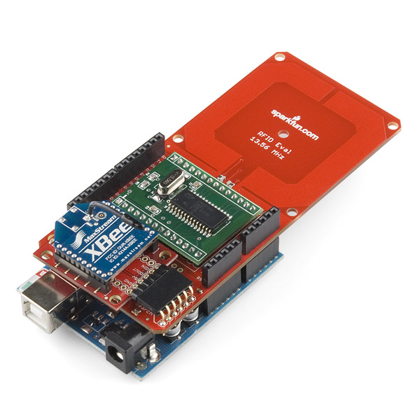
SparkFun RFID Evaluation Shield - 13.56MHz
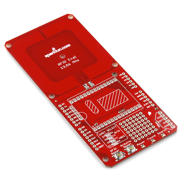
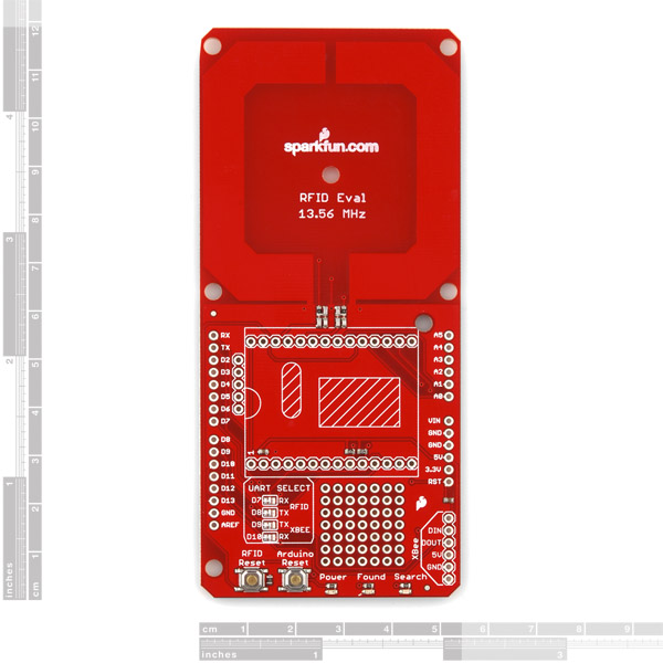
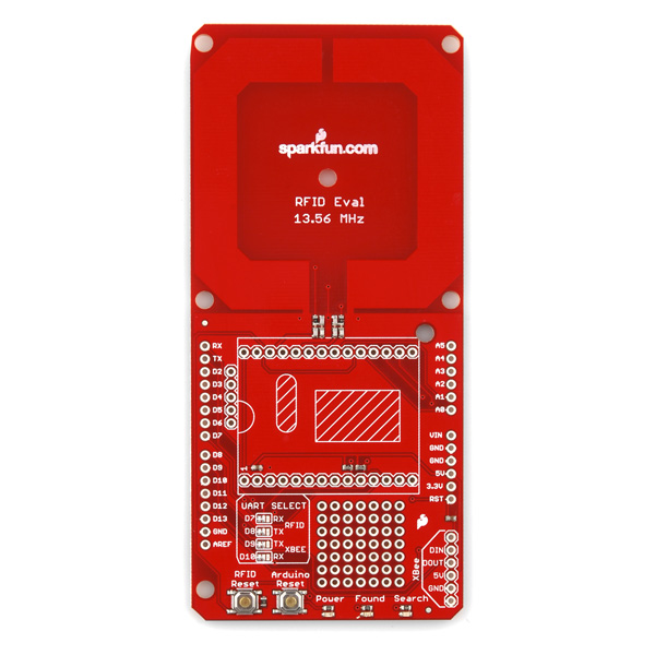
This board is an evaluation platform for the SM130 RFID module. It includes an XBee header, PCB trace antenna, and has the layout to be used as a shield for an Arduino. There is a small prototyping area as well. This board can also be used as an antenna to the SM130 RFID module. Be sure to check the schematic for information on the connections.
The XBee header is designed to be used with the XBee Explorer Regulated board.
This board comes populated with the switches, resistors and LEDs, but does not include the RFID module, XBee, headers, or Arduino board.
SparkFun RFID Evaluation Shield - 13.56MHz Product Help and Resources
Core Skill: Soldering
This skill defines how difficult the soldering is on a particular product. It might be a couple simple solder joints, or require special reflow tools.
Skill Level: Rookie - The number of pins increases, and you will have to determine polarity of components and some of the components might be a bit trickier or close together. You might need solder wick or flux.
See all skill levels
Comments
Looking for answers to technical questions?
We welcome your comments and suggestions below. However, if you are looking for solutions to technical questions please see our Technical Assistance page.
Customer Reviews
No reviews yet.
Its there any support for designing a bigger antenna? or boosting this one´s range?
-------------------- Tech Support Tips/Troubleshooting/Common Issues --------------------
Try looking at my comment posted on the SM130 module for some tips and FAQ => [ https://www.sparkfun.com/products/10126#comment-5892d719fa2a503f638b4567 .
FYI I've had Luck sawing this board in half to create a remote antenna. I left the the trimmer capacitors on the antenna half and brought ground and the two antenna lines direct to the SM130 module pins. In my case these pass through a DB25 cable (Antenna ground is connected to the cable shield at both ends). It's a little hard to explain without detailed build instructions. Performance appears to be largely unaffected but I've modified all the boards that I have so a side-by-side comparison is not possible. A handy mod to the next rev of this board would be to make it perforated so the user could easily relocate the antenna.
Do you have any pictures of how to saw the board? Where do you solder wires to connect the separated boards? I'm looking to do the same thing for a Maker Faire project this weekend.
Did you ever figure out how to do this?
is D7 - D10 only need for the shield to work apart from power, which reminds me to ask which power does it need, 5 or 3.5v?
It uses 5V. And yes, you technically only need D7-D10.
D7-D8 are used for the RFID module, and D9-D10 are used for the XBee module. (If you don't care about XBee, you can make due with just D7-D8.)
If you use this eval board with the Leonardo, using digital pin 7 as the serial receive pin will not work. I recommend using using the solder switches to use the hardware serial. (Or temporarily jumper pin 7 to pin 0 and pin 8 to pin 1)
See Leonardo note on this page: http://www.arduino.cc/en/Reference/SoftwareSerial
Hi! The sketch provides the pin 13 is used as the Reset. Can it be changed? I saw number 13 in the Software serial library(since this one is used and not a specific library for this product), is this the pin the sketch is talking about? Is it safe to change it? or do you know a line of code or a library which implements altering the reset? By the way, I'm concerned with this pin since I'm using an ethernet shield which is on SPI and uses the pin 13. Or can I just leave it alone? :) Thanks for the replies. That would be a great help for my college final year project. :)
Arduino NFC RFID: http://www.elecfreaks.com/store/nfcrfid-breakout-module-p-519.html
Is it possible to change the reset to any other GPIO pin? Can it be done manually? Like if it's intended for D13, I would redirect it to any other pin? Or should I configure it first via software? Or is it hard wired to 13 and cannot be changed? thanks for the reply. I'm using another device which is in SPI, particularly the RC522 RFID Reader which is hardwired to 11,12 and 13 for MISO, MOSI and SCK.
Is this shield is compatible with Arduino Yun? When I tested this shield with Arduino UNO, it worked well. However it didn't work at all with Arduino Yun. Anyone have any perspective?
Does anyone know what the field strength of this is? I bought some sticker tags but the reader is reading them. It could be the field strength isn't enough. Also, maybe (And likely) I don't fully understand the requirements of MIFare compliance.
First off, thanks for providing the example code! It's definitely great for getting started. That said, I'd like to note my disappointment with the almost total lack of comments. The code would be more useful with better documentation. Please let me know if I'm missing something.
did you receive yours? I'm wondering what exactly comes with and what doesn't... since it states: "RFID module, XBee, headers or arduino board" However it doesn't explain whether it comes with the XBee explorer and no one seems to want to answer this... I'd appreciate it if you could provide this info.
Thanks
This board does not include: RFID module, XBee, headers or arduino board.... so does it include the Xbee explorer regulated board? I'd appreciate a fast reply! Thanks!
Can anyone tell me if this can read MiFare Ultralight Tags?
As well, is there supporting code for reading the Ultralights? They are 7 byte UIDs.
Nevermind, I answered my own question by looking at the SM130 breakout board: Supports ISO14443A Mifare Classic 1K , Mifare Classic 4K , Mifare Ultralight
Has anyone ever tried to use this with the SM130 to read their corporate RFID cards? I noticed my card says HID iClass DH, and I believe that to be in the 13.56MHz space, but I'm not getting a read.
My assumption is that the card should return something, even if i cannot decode it, but I'm seeing nothing when i hold my card to the reader (even though it reads other cards I have here).
Anyone have any perspective?
iClass is a protocol like mifare. If your cards are like my school IDs, they are likely 13.56MHz but the reader isn't registering them because the protocols don't match. I'm working to see if I can overcome this but I'm not having any luck. I'm also just starting on it so if I make a breakthrough, I'll post again about it.
A lib for this shield is available at : https://github.com/pi3rrot/SM130/
I am actually working to improve this lib to Read/Write full Mifare tag. Contribution is welcome ! ;)
I'm having trouble using this board with Ethernet shield. If someone can point me how to properly set pins I would be grateful. Ethernet part of my sketch works fine, but when I add RFID board, there is some obvious pin collision because, even if I don't setup RFID sketch parameters, "found" LED activates at the same time as "TX" LED on Eth. shield. Thanks in advance!
Here are the changes to do for the "Tag ID Example code" if you are usind Arduino 1.0 or later : Replace "NewSoftSerial" with "SoftwareSerial" (twice) and change the lines like "rfid.print(255, BYTE);" with "rfid.write(byte(255));" (10 times in this code) And now it will work !
I did this and I get the "START" message but that's it. The "Found" and "Search" LEDs don't do anything and nothing new appears more on the serial terminal. I testing it with the tag SEN-10128 but have also tried various cards in my wallet.
Any idea what's going wrong?
Found the problem. The Arduino was sending strings to the RFID instead of bytes. Need to change rfid.print(number) to rfid.write((uint8_t)number) in functions: halt() and seek(). Works great now!
I uploaded working code to: https://github.com/SebMadgwick/RFID_Eval_13_56MHz
/* hello guys if you have MEGA 2560 YOU NEED TO DO THIS STEPS IN ORDER YOU READ THE TAGS ALL ITS THANKS TO (Michelle) for her support in SparkFun Electronics
the code its here which have been modified a little in order to make this works dont forget that you need jumpers to run from the rfid eval to Arduino
/ /
rfid arduino RST RESET 3.3V 3.3V 5V 5V GND GND GND GND VIN VIN A0 A0 A1 A1 A2 A2 A3 A3 A4 D20
A5 D21
AREF AREF GND GND D13 D13 D12 D12 D11 D11 D10 D10 D9 D9 D8 D51 D7 D50 D6 D6 D5 D5 D4 D4 D3 D3 D2 D2 TX0->1 TX0->1 RX0->0 RX0->0 */
/* RFID Eval 13.56MHz Shield example sketch with Value Block Read/Writev10
works with 13.56MHz MiFare 1k tags
Based on hardware v13: D7 -> RFID RX D8 -> RFID TX D9 -> XBee TX D10 -> XBee RX
Note: RFID Reset attached to D13 (aka status LED)
Note: be sure include the NewSoftSerial lib, http://arduiniana.org/libraries/newsoftserial/
Usage: Sketch prints 'Start' and waits for a tag. When a tag is in range, the shield reads the tag, blinks the 'Found' LED and prints the serial number of the tag to the serial port. It then attempts to authenticate memory block 0x01. If this is successful it will display the "Success" status message and the contents of memory block 0x01. It will then ask for a 4-byte input to write to the tag. After receiving a 4-byte input, it will attempt to write this data to the tag and return the write status.
This code uses the default transport key to authenticate the Value Block 0x01. If you have already written a key to this block in your MIFARE tag, the code may not work properly.
*/
include
NewSoftSerial rfid(50, 51);
//Prototypes void check_for_notag(void); void halt(void); void parse(void); void print_serial(void); void read_serial(void); void seek(void); void set_flag(void); void authenticate(void); void write_Block(void);
//Global var int flag = 0; int Str1[11]; int Str2[11]; int Str3[11]; int Str4[11]; int Str5[4];
char in1 = 0; char in2 = 0; char in3 = 0; char in4 = 0;
int chksum;
int flag2 = 0;
byte auth = 76;
//INIT void setup()
{ Serial.begin(9600); Serial.println("Start");
// set the data rate for the NewSoftSerial ports // xbee.begin(9600); rfid.begin(19200); delay(10); halt(); }
//MAIN void loop()
{ read_serial(); }
void check_for_notag() { seek(); delay(10); parse(); set_flag();
if(flag = 1){ seek(); delay(10); parse(); } }
void halt() { //Halt tag rfid.print(255, BYTE); rfid.print(0, BYTE); rfid.print(1, BYTE); rfid.print(147, BYTE); rfid.print(148, BYTE); }
void parse() { while(rfid.available()){ if(rfid.read() == 255){ for(int i=1;i
Hello,
Does this shield use up pins D2-D6? Saw the schematic & it just says that it's connected to JP6?? Can i use the D2-D6 pins for other use(using them as GPIOs)?
Btw, a big thanks to Sparkfun (and of-course the designer of this shield) for making such a cool shield.
I just ordered one of these and got an RFID worker working in one evening. A few useful notes:
The SM130 will read MiFare cards. This means that it's compatible with NFC-enabled Android phones, such as the Galaxy Nexus!
The SM130 operates over either serial (UART) or I2C. This eval board only gives you access to the serial lines.
XBee is totally optional. If you just want a quick way read NFC tags, this board is the way to go.
I have no clue what the intended purpose of the UART select pads is.
If you're using this with an Arduino Mega (or the Android ADK), be aware that D7-D8 do not support change interrupts, and therefore are not suitable for serial communication. You'll need to use jumper wires to connect to different I/O pins. (See http://arduino.cc/hu/Reference/SoftwareSerial for supported pins.)
The RFID module needs to be manually reset after powering on your Arduino, which seems to be commonly omitted from sample code. (This can be done using D13, or the RFID reset button on the eval board.)
The RFIDuino library is compatible with Arduino 1.0, whereas the example code provided is not. You can grab it here: https://github.com/marcboon/RFIDuino
From looking at the schematic (I don't have this board... yet) it appears that the I2C is also connected and you can just choose which one to use.
Also, the two pairs of serial jumpers seem to allow either the xbee or sm130 to be connected to the hardware serial or to two digital pins (7&8 for sm130 and 9&10 for xbee) for software serial allowing for maximum flexibility. You could stack another shield using the hardware serial if needed. Hope this helps others and someone correct me if I'm wrong.
The example code works fine with Arduino 0.23. But doesn't work with Arduino 1.0
I used this device for creating a door opener in our MIT Media Lab offices. Works very well with the Boston MBTA Charlie Card. :)
http://colorsaregood.com/access.jpg
Couple things I learned playing with this board and the sm130
a) Timing is critical for some operations. Need to delay 20ms or so on most operations before checking the status code.
b) This library makes it pretty easy to work with the sm130 : https://github.com/Arachnid/sm130
c) Mounting the sm130 with headers is a good idea, if you plan on flashing the firmware at some point.
d) most tags will require auth'ing multiple times before you can read a block.
Hi, Thanks for the comment. Can you explain a little more about point c. I am attempting to update firmware, and running into a timeout. No response error. I can't seem to find my way around this issue. Thanks,
Any luck using this with arduino1.0? Does anybody have some new sample code?
Anyone know the approximate read range for this with the SM130, my application needs around an inch.
also if anyone knows of a different reader with more range for a similar price let me know please!
It depends on the tag and sometimes, what material you have in between the tag and reader. With the transparent tag (in the related items) and nothing in between, I was getting about an inch or better.
Why do they bring the 5v to the xbee header when xbee needs 3.3v
Good question. The XBee header is designed to be mated with the XBee Explorer Regulated. I added this part to the related items and a note to the product description. Thanks for inquiring!
Anyone know if i want to make the antenna part into a custom PCB board how i can do that or where to read up on it??????
A great app note on MiFare antenna design can be found here.
Basically, you want to make a coil that will provide a strong enough magnetic field to create induction for the tag. The greater the area and more turns your coil has the more magnetic flux and the longer the range (among other factors). The hard part is tuning the coil to the desired frequency/s. This is achieved by some caps and resistors that form filters at the antenna inputs. All I did was get some variable caps and resistors and physically tune the antenna until you pick up the signal. Once it works, measure the values with a DMM and use the closest standard values compnents. I'm sure this is not the best way, but it works. Or if you want to take an even bigger shortcut, just copy the eagle files.
Hi everyone,
I'm wrinting an open online guide to using the SM130 with the arduino shield (also available on sparkfun) check it out if you are looking for help with the SM130 or add to the document if you have anything to share.
the document can be found here
Have fun!
I am new to RFID.. Can somebody explain the functions of the xBee and can any Arduino Board be connected to the shield?
I have built exactly this; Arduino Uno with this RFID Evaluation Shield, the SM130 Mifare module, XBee Explorer Regulated and an XBee Pro ZB.
Also an XBee Explorer dongle and another XBee Pro ZB.
I built a simple Aurdino program using the NewSoftSerial lib.
Communication between both XBee units works perfectly.
The RFID reader works fine aswell, EXCEPT that I get the damn Firmware message from time to time (like it thinks I requested it? Which I have not, or it resets itself randomly??).
Apart from that the RFID reader works fine (on its own, that is when I use Serial.print() to show the swiped tags etc.).
If I add xbee.print() it gets all fucked and allt that is printed to both Serial and sent over the XBee communication is the Firmware version over and over and over again with about 1 seconds interval. The RFID reader gets totaly blocked and does not accept tags.
I put it in SEEK mode, it returns Firwmare version.
I put it in SEEK mode, it returns Firwmare version.
I put it in SEEK mode, it returns Firwmare version.
I put it in SEEK mode, it returns Firwmare version.
I put it in SEEK mode, it returns Firwmare version.
over and over. This only happens randomly once every 15-20 seconds with out the xbee.print() code, but when I add it thats ALL I get, and not tags what so ever...
wtf? bug??
code:
include
NewSoftSerial rfid(7, 8);
NewSoftSerial xbee(10, 9);
// commands
byte SEEK[] = { 0x82 };
// methods
void send_command(byte command[], byte length);
void rfid_read(void);
void rfid_print(void);
void setup() {
Serial.begin(19200);
Serial.println("Start");
xbee.begin(9600);
rfid.begin(19200);
delay(10);
send_command(SEEK, 1);
}
void loop() {
rfid_read();
}
// [FF] [00] [LENGTH] [COMMAND] [DATA] [CHECKSUM]
void rfid_print(byte buf[], byte length) {
Serial.print("PACKET LENGTH (DEC): ");
Serial.print(length, DEC);
Serial.print(" COMMAND: ");
Serial.print(buf[0], HEX);
Serial.print(" DATA: ");
for(byte i=1; i
Hi All! I bought this shield and connected it to my Arduino UNO, what else should I do to make a simple test of TAG identification? should I write some code to enable the RFID Module? what about the jumpers located near the protoboard? thanks a lot for your help
This board actually barely runs into the USB port on the duemilanove preventing it from fully seating. As far as I can tell all the pins still make a good connection, it just seems like an easily preventable oversight.
I have an ID20 and am really happy with it. Does anyone have an approx. read range for this board? I know it depends on a lot of variables, but just ballpark range would be nice. Thanks!
I purchased this board and SM130 module and used the "Tag ID Example Code" as the framework to my program. The code works fine, but the range is really limited. I could get it to work at 1/4-inch away from the antenna, and that's about it! I also found that the transparent tags work better than the "laundry" tags. The "laundry" tags barely works even when making physical contact with the antenna. Not sure if the code is hindering the range, but I've found it this set up to have very limited use given the poor range. If anyone can think of something to help please let me know. Thanks.
I know am kinda late to reply. But I used an external power adapter to Arduino and now i get nearly 1 inch of distance with the laundry tags.