- Home
- Product Categories
- Components
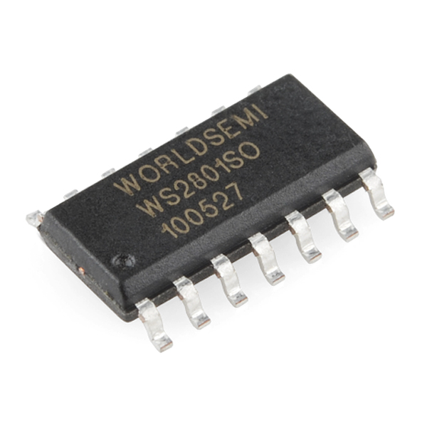
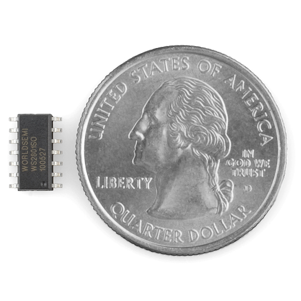
- WS2801 IC

WS2801 IC
You may recognize the WS2801from our addressable RGB LED strips. These 3-channel constant current LED drivers are great for controlling chains of RGB LEDs. The IC is controlled by a 2-wire serial control scheme that allows multiple ICs to be chained together.
Use a handful of these ICs in conjunction with some RGB LEDs to make color displays, or with regular LEDs for a monochrome display three times the size. Or just the WS2801 to free up PWM pins on your microntroller by controlling multiple LEDs with two pins.
- 2-wire control scheme reduces system cost
- Built-in PWM dimming scheme for each channel
- PWM free-run capability
- Power supply voltage 3.3-5.5v
- Supports both constant current and constant voltage drive modes
- Wide constant current range from 5-150mA
- Datasheet (WS2801)
WS2801 IC Product Help and Resources
Core Skill: Soldering
This skill defines how difficult the soldering is on a particular product. It might be a couple simple solder joints, or require special reflow tools.
Skill Level: Competent - You will encounter surface mount components and basic SMD soldering techniques are required.
See all skill levels
Core Skill: Programming
If a board needs code or communicates somehow, you're going to need to know how to program or interface with it. The programming skill is all about communication and code.
Skill Level: Rookie - You will need a better fundamental understand of what code is, and how it works. You will be using beginner-level software and development tools like Arduino. You will be dealing directly with code, but numerous examples and libraries are available. Sensors or shields will communicate with serial or TTL.
See all skill levels
Core Skill: Electrical Prototyping
If it requires power, you need to know how much, what all the pins do, and how to hook it up. You may need to reference datasheets, schematics, and know the ins and outs of electronics.
Skill Level: Competent - You will be required to reference a datasheet or schematic to know how to use a component. Your knowledge of a datasheet will only require basic features like power requirements, pinouts, or communications type. Also, you may need a power supply that?s greater than 12V or more than 1A worth of current.
See all skill levels
Comments
Looking for answers to technical questions?
We welcome your comments and suggestions below. However, if you are looking for solutions to technical questions please see our Technical Assistance page.
Customer Reviews
No reviews yet.
Glad you have this as a separate product now :) though a more descriptive name might help others find it
I wrote some code for the propeller to get this guy working. It only supports 1 WS2801 right now but I am working on one that will work with a long chain of them. This code is mainly for using the WS2801 to control a set of mosfets which is good when you don't have allot of CPU time to dedicate to controlling PWM.
youtube video about the chip: http://www.youtube.com/watch?v=EugcTOxVHx8
Propeller Code: http://longhornengineer.com/code/WS2801_Driver.zip
Would be awesome if Sparkfun carried the WS2803 or the DIP version of the WS2801.
Seconded that the DIP version would be great.
Awesome, now source the WS2803 please! Three times the outputs on one IC at only a marginal cost increase per the manufacturer (I had them quote me but the min order quantity was 3000 pcs I believe...)
i am trying to use a higher current (350ma) white led with this IC. i was hoping to combine all 3 channels to feed that one led. is that possible? or is there a chip for higher current leds? thx.
You might be able to drive a transistor or a mosfet with this. Your current requirement is relatively low, so a small signal transistor will probably work as long as you remain within the maximum watts dissipated on the transistor. I would recommend picking a transistor whose maximum wattage is 25% to 50% higher than the normal load of the circuit. The cost increase would be marginal for this type of thing, and it will probably last longer.
I want to run these at 12V with 3 LEDs connected to a single chip. I need 5V zener diode + filter cap as datasheet says to make chip work on 12v. What about R/G/B feedback pins: are resistors on them a must? If no resistors, current is not limited and I should be careful not to exceed max. output current? Should I connect them to ground or leave them float? Also, the LEDs. Can I connect them in series although datasheet says max. output is 7V? Will brightness be lower? I have seen some strips with three LEDs in series including current limiting resistors on them connected to a ws2801. How that works?!? Thanks :)
has anyone tried this with common cathode RGB LEDs? such as the 5mm Piranha?
My favorite thing about SparkFun is learning about components I didn't know about before. I bought some of these and made some small circuit boards (toner transfer method) that have just the chip, the 3 sense resistors (I had some 27 ohm SMD), a decoupling cap and a through hole RGB LED. I daisy chained 3 of them together, and they worked right off the bat. I wrote a very simple function for Arduino that sends the pulses out with no delays, and it works just fine. I agree with the other commenter, only the 3 sense resistors are needed.
helloooo?
Here's my solution, using two SOIC-8 breakout boards. http://www.flickr.com/photos/63139006@N08/
—
What form factor is this chip? It doesn't fit the soic to dip adapter board
SOP-14
It appears both common cathode and common anode RGB LED's can work with this, but all of the example application circuits in the datasheet are common anode.
The built-in PWM is a very nice feature, but the requirement for 6 resistors for one RGB LED to attain constant-current operation is a bit overkill.
Since I multiplex PWM on the microcontroller (using "bit modulation" to relieve much of the computing overhead), I prefer the PCA9922 which is a shift-register-style 8-channel constant-current LED driver with one resistor to set the current on all channels from 15mA to 60mA. It also supports a separate power supply for analog (the LEDs) and digital.
I designed a board that seems to work okay that puts two chips on opposite sides of a dual-sided board to drive 5 RGB LED's (15 channels) plus a spare, optional LED for debugging, etc.
You can drive it with just 3 resistors on the feedback pins and you'll be fine.
Anyone that wants to run this chip VERY easily from an Arduino should look at the FASTSPI lib: http://code.google.com/p/fastspi/
FAR better than the example approach.
Is there anything similar to this that can put out 350ma per channel?
This IC plus three higher-current external transistors? Just use them as switching amps. Then you have all the current/voltage capacity you want if you design it right.
Wouldn't that mess up the constant-currentyness?
I think the datasheet mentions the use of transistors to increase the output current.
is this like this http://www.sparkfun.com/products/9622 ?
Hmm, says Constant current ratting up to 150ma here, but in the spec sheet it says only 50ma in the tables. The table also says CV mode max current is 100ma, but in the paragraph on CV mode it says max is 50ma.
So what gives? What are the correct numbers?
Though it doesn't specificaly say in the datasheet, I would assume that it is 50ma/channel times 3 channels equaling 150ma max. I base this assumption off of the maximum power dissapation of 600ma.
They come in dip too ;). SOICs are scary. Not to mention LFBGAs...
This is exactly what I've been looking for!
One of my projects involves controlling the brightness of 6 Led arrays. The problem is that the Atmegaxx8 only has 6 pwm pins, and one of them is inconveniently located on the MOSI pin, which I need.
I designed an eagle part for this component. It is untested, but it can be found in this library.
I created a part for this as well, and have tested it extensively in several projects. Download here.