- Home
- Product Categories
- Kits
- SparkFun Simon Says - Through-Hole Soldering Kit

SparkFun Simon Says - Through-Hole Soldering Kit
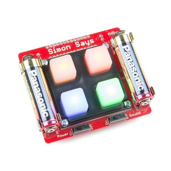
This is the latest version of our popular through-hole Simon Says Kit. We've made some changes to the board that should make it easier than ever for the beginner to build! All components are through-hole, making this kit a great place to start when you're learning to solder. When building this kit, you'll have a chance to solder a 28-pin microprocessor, LEDs, battery clips and more.
After you have successfully assembled the kit, you will have a greater knowledge of through-hole soldering and the tools, techniques, and terminology required to populate your own PCB prototype. You will have a development platform with 5 outputs (LEDs and buzzer), 5 inputs (buttons), and serial for debugging. And, of course, you'll have your very own Simon game!
Checkout the assembly instructions - we're pretty proud of them. The kit even includes batteries! Assembly time varies, but for a true beginner with no soldering experience, the kit can take 20-40 minutes to assemble. A soldering iron and wire cutters are the bare minimum tools required. We scoured the earth and found a really fantastic beginner's soldering iron for $10, solder for $2, and wire cutters for $2. We also have a Learn to Solder version of the kit which includes all the tools you'll need!
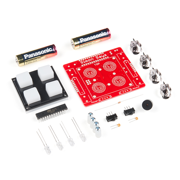
- 1x ATmega328 - pre-programmed with Simon firmware
- 1x Buzzer
- 2x 0.1μF Cap
- 1x 10K Resistor
- 4x LEDs (blue, yellow, red, green)
- 2x Slide Switch
- 4x Battery Clips
- 2x AA Batteries
- 1x Button pad
- 1x Bezel
- 4x Standoffs and screws
- 1x Assembly instructions
- Schematic
- Eagle Files
- Assembly Instructions
- Soldering Tutorial
- Bootloader Note
- Code
- GitHub (Design Files & Example Code)
SparkFun Simon Says - Through-Hole Soldering Kit Product Help and Resources
Simon Splosion Wireless
February 13, 2014
This is a tutorial demonstrating one of many techniques to "hack" the Simon Says. We will highlight the technique to take your Simon Says Wireless.
Simon Says Assembly Guide
January 20, 2011
No matter what flavor of the Simon Says Through-hole Soldering Kit you've purchased, this tutorial is here to guide you through the entire build process.
Simon Says Experiments
October 21, 2010
So you've built up a Simon Says kit? What next? This tutorial will get you up and running with Arduino software, guide you through a few example sketches, and send you on your way to create your own. Careful, this stuff is highly addictive. :)
Core Skill: Soldering
This skill defines how difficult the soldering is on a particular product. It might be a couple simple solder joints, or require special reflow tools.
Skill Level: Rookie - The number of pins increases, and you will have to determine polarity of components and some of the components might be a bit trickier or close together. You might need solder wick or flux.
See all skill levels
Core Skill: DIY
Whether it's for assembling a kit, hacking an enclosure, or creating your own parts; the DIY skill is all about knowing how to use tools and the techniques associated with them.
Skill Level: Noob - Basic assembly is required. You may need to provide your own basic tools like a screwdriver, hammer or scissors. Power tools or custom parts are not required. Instructions will be included and easy to follow. Sewing may be required, but only with included patterns.
See all skill levels
Core Skill: Electrical Prototyping
If it requires power, you need to know how much, what all the pins do, and how to hook it up. You may need to reference datasheets, schematics, and know the ins and outs of electronics.
Skill Level: Rookie - You may be required to know a bit more about the component, such as orientation, or how to hook it up, in addition to power requirements. You will need to understand polarized components.
See all skill levels
Comments
Looking for answers to technical questions?
We welcome your comments and suggestions below. However, if you are looking for solutions to technical questions please see our Technical Assistance page.
Customer Reviews
4.7 out of 5
Based on 42 ratings:
1 of 1 found this helpful:
Great Kit!
I bought this kit for my son. He had a great time building it and kept saying how much fun electronics were. The kit and the instructions are both high quality. The instructions are very clear and have nice pictures.
After he built the kit and put the batteries in, nothing happened. That was because the batteries were not making good contact with the battery holder ends. Just make sure the batteries make contact with the ends. If not, just bend the battery holders ends slightly with gentle pressure for a snug fit.
This is a great kit and a fun game to play.
1 of 1 found this helpful:
I had ordered the SMD version of this project by mistake and then found out that there was not enough in stock of the Through-hole-sodering kits due to the holiday sale off to meet my class requirenments. So I had to try and have my class solder the SMD's instead of the the through-hole soldering project.This was a big mistake as to the having first time students try and solder something so small. Only 65 % of the class were able to finish and have the kit work for them. Parts were not available to help those that made mistakes and lost the small pads on the components . So I had to use the additional kits as spare parts.
3 of 3 found this helpful:
Great for teaching soldering!
I used this kit in a soldering work shop a few weeks ago. A few people there had some soldering experience and just wanted to brush up on and hone their skills. The majority, however, had no experience what so ever. This little kit was perfect for both groups.
Soldering the first few components in gives people a chance to practice and really learn what soldering is all about. Then, my favorite part, is the ATmega. All the pins allow for the development of technique. You don't have to put the iron down and get the part all set, you can just focus on going through the motions over and over and over. It was interesting to look at the ATmega joints with the students afterwards to see how much their joints improved as they worked through the part. It also gives the confidence to solder the harder parts like the battery clips.
Speaking of battery clips, that was the #1 troubleshooting issue we found, they need to be flexed in just a bit to get a good contact. The instructions are also very clear and engaging.
In short: GREAT KIT! Lots of joints to practice on and the final product looks and feels greats. Real confidence booster!
2 of 2 found this helpful:
Easy build, great platform for further programming
I supervised two builds of these (girls ages 8 and 9) and all went smoothly. The kids absolutely loved putting it together and playing with the pre-programmed game afterward.
The board is easy re-programmable with the Arduino tools and minimal extra hardware, plus additional IOs are available on the side, making this a great tool for getting started with Arduino programming. Think of it like an Uno/Redboard with buttons, LEDs, and buzzer already provided!
Note, If you want to go back to the Simon firmware (or hack on it), it's available on SparkFun's page on GitHub.
3 of 3 found this helpful:
My daughter loved putting it together
She's 8, and put this together with zero debug time. Very satisfying for her. I meant to give this 5 stars, but this web interface disagrees with me.
I think it was most helpful that we we had a slender soldering pencil (Weller, 12-V), which puts out enough heat to get the job done (and no more) and which fits perfectly in a child's hand. My other irons are too hot for the job and too fat for a kid's hands. An "extra hands" is also helpful, but not 100% necessary.
cool little project
This was a lot of fun to put together, instructions were very clear and easy to follow. Simon works great has bright LED's and sound is good and loud. I used it for soldering practice for an upcoming box mod project. I wish there were more reasonably priced project kits like this.
EPIC
A co-worker showed me the website after a conversation about home projects I was looking into. I trolled around the sparkfun webpage and found a beginner project that was a great way for me to break into soldering. I got (2) of the Simon says game and had a blast putting it together. I keep one at my desk at work and all the engineers play a game or two when ever they walk by. I also gave the second game to my daughter. It's a little advanced right now but she has a blast figuring it out. Next step is to do some coding with the program.
My kids love it, easy for my son to build
My 10 yr old was able to put this together with little help from me. He does have some soldering experience. The instructions are well written, easy to follow. The kids love playing with it.
Excellent, my son loved it!!
My 7 year old son and I built this. He loved it, it was his first time soldering. Great project.
What a fabulous kit!
Bought a set of these to work on the Electronics Merit Badge with a group of Boy Scouts. All of the boys were able to learn their soldering skills and come out with a working game. I really appreciated the extra traces on the circuit board that allowed for the reversing the polarity of the LEDs, as this enabled us to fix one young man's board where he installed one LED backwards. Great job SparkFun!
Nice kit
Bought this to help teach the kids how to solder and get into electronics. Not only was it fun for us to put together, it has been fun to play with as well.
Fun little toy
Easy to assemble --a very beginner could do it without any problem. Nice and fun little toy, working perfectly, as advertised. No con's, only pro's !
Excellent teaching tool with a fun device
I bought this to teach my daughters (ages 12 to 18) to solder. The kit is very well done, the instructions and markings were clear. We could focus on assembly and not trying to puzzle out the proper component positioning.
The battery clips had to be bent in a bit in order to make contact. This is not really a fault in the kit, just a note that the clips will have to be bent in slightly. This was a great opportunity for them to learn a little about tracing issues, without having to desolder components. Out of 4 assemblies we only had one LED that didn't work. Our initial assumption was that the polarity was reversed and we reviewed the instructions to cut the traces instead of desoldering (a nice feature). Upon closer inspection we found a trace of solder had shorted the connection, so she got to learn to use desoldering braid to clean it up.
All of them were very happy when their games first lit up and gave great reviews to the experience.
Super job! Great kit!
My 9 year old built this with some help from me. It was a thrill for both of us.
I was a little apprehensive as we got to the long DIP, but he did the soldering just fine, with almost no help. Two things struck me about the DIP package. a) cutting off pin 15 and leaving out the via hole was an inspired bit of human engineering -- that's a sign that y'all are really thinking through the process -- three cheers! b) y'all prebent the DIP pins so they fit in the holes. Brilliant!
I hope the team at Sparkfun knows how good a job they did on this. I do.
matt
Very cool!
Fun to build fun to play. Worked perfect!
So simple a 10 year old could do it
In fact, I'm a 10yr old and I just finished making the kit with my dad.
The lights work and the game plays fine, but for some reason we don't get any sound.
We checked that the buzzer is soldered in the correct direction and the slide switch is set right. Did any one else have trouble with sound?
UPDATE: Yep, just as promised they sent us a new mini-speaker. We plunked it in and now our Simon plays sound! Great kit. Great company.
Sorry to hear that you're having buzzer issues. Our amazing Tech Support Team is working on your issue, and will be in touch with you directly.
Easy kit to assemble
I had no issues assembling this kit. The instructions were clear and very good. The only question I have is how to distinguish which color led goes in which position. The tones played are associated with a specific color in the original game, but there is no indication on the leds as to their color and which position they should be soldered in. Just a minor point that does really affect how the game plays. My grand kids loved playing with it.
Twice the fun
We gave this as a gift to our 11 year old to do with grandpa. He had a great afternoon making it with grandpa and now loves playing with it all the time. The only thing to make this better for the parents would be to have a volume control (louder to softer) instead of on and off. I will give one to my niece (also 11) for Christmas to do with grandpa too.
Great Kit
Instructions are super, simple enough to get started. Battery clamps needed some tweaking though.
Excellent Soldering Project
Used these for a Maker Space event. Had the kids solder a few components on scrap boards first to get the hang off it then do their kits. No problems getting them assembled and working. Used lead free solder from Sparkfun. The lead free solder worked well with the 50W Weller soldering irons I had but I wouldn't recommend using it with low end irons. Tried that as home first and had a hard time getting the irons hot enough to work well with the lead free solder.
Great Learning/Soldering Opportunity and Post Use
We just completed our Maker/STEAM Camp ages 9 through 14 were able to assemble the Weevil-eye and a follow up with the Simon Says soldering project without much trouble. We expect and celebrate when a camper goofs-up and is able to desolder with a pump or wick to correct their mistakes. Even with the battery holder issues with continuity having to bend the battery holder clips ads to the experience.
All in all, we love you guys!
Thanks for the support and documentation that you provide for your customers.
Best,
Dave Holzwarth Physics/Math Teacher Maker Space Coordinator and Instructor Mercersburg Academy Mercrsburg, PA 17236
Good beginner project
Clear directions. Great way to practice soldering.
Fun!
My son and I enjoyed building, troubleshooting and now playing with this kit. We've got three new ones in the hopper, looking forward to more fun!
A little too simple maybe
Great instructions. Good soldering practice. It'd be more useful if it included programming headers. It also doesn't really explain what you're building. It's a stripped down Uno and 99% micro-controller+code with a tiny bid of solid state components but it's 15 minutes to a working game, so great for getting some fast positive feedback that you're making progress.
really nice solder kit
introduces electronic parts, and soldering instructions, and it plays!!
Lots of fun for soldering classes at our makerspace!
I teach a soldering class at our makerspace, and these kits have been a lot of fun for attendees! I get most of my kits from sparkfun for these classes, and try different ones each month to switch it up and keep it interesting (for both the attendees and me). This one is super easy to put together, but still enough of a challenge that newbies will have to sweat a little to get it done. They're always intimidated by the microchip with all the closely spaced pins.
Only critical thing I have to say about it is the battery holders need to get pinched in a little before you put the battery in, they don't seem to make good contact otherwise and it will reset if it gets moved to much. I was also momentarily confused when I noticed one chip was missing a leg because I thought I broke it off, but realized they come like that when I looked at the other ones.
My 10 year old loves it
My 10 year old really likes the Tetris and Simon Says electronic puzzles so when he saw that he could solder his own, he was very excited. This was his second solder project and we completed it the day it came. The online video and instructions were great and I was only there to keep the solder from destroying the dinning room table. I can't wait to get him interested in re-programming it using the provided pin-outs. Awesome touch, thanks!
Total FUN! Watch for battery clips and upside-down LEDs.
I had five children (mostly ten year olds) complete this project in 40 minutes. I was amazed and they were absolutely delighted. They had previously completed Sparkfun's LED flashlight kit and proto-pic's lighthouse kit with me and that's all the electronics experience they've ever had. Proof, I think, of the excellent quality of this kit and Sparkfun's outstanding printed instructions (one of the difficulties I had with the lighthouse kit was that it didn't include instructions and while the website was good it didn't print well which is trouble in a group setting).
Minor "gotcha's": The battery clips in three of the kits didn't properly press against the battery. A simple fix (bend the ends in) but without that little wrinkle, those children would have finished a working project completely by themselves. Two of these young engineers placed the LEDs on the wrong face of the PCB. Desoldering is more than we can manage without melting the LEDs so I'll have to replace those (can anyone tell me what sort of LEDs to use?)
I'm looking forward to customizing these kits in weeks to come.
Some reviewers discuss tools. FWIW, We used cheap ($8) adjustable temperature irons, lead-free rosin core solder and bronze wire type cleaning sponge. Most of the students preferred to use helping hands to hold things still. We also used (Hakko) flush cut wire cutters. Apart from that, everything was in the box - even batteries. Nice.
Flashlight kit: https://www.sparkfun.com/products/14877 Lighthouse kit: https://www.sparkfun.com/products/14635
I can't say enough good things about this kit!
Thank you for the nice review!
In case anyone else needs them also, the LEDs we use in this kit are as follows: * LED - Super Bright Red * LED - Super Bright Blue * LED - Super Bright Yellow * LED - Super Bright Green
Happy Hacking!
Fun and thoughtful
This was perfect for my son and daughter (ages 9 and 10). They learned how to solder and were excited about it! Clear instructions. Fun toy when finished.
My only feedback to SparkFun is that one of the slider switches broke fairly soon after completed. Mechanically the switch fell apart.
Nice!!!!
Good for exercising memory
STEAM Camp Winner
Great little kit for our STEAM Camp (Camp PaGG). Good soldering exercise without being too complicated. The campers are going to love this.
Purchased for my six year old and he loves it.
The instructions and components are great. My six year old was able to solder the whole thing and still loves to play it (and show off his work).
Simon Says, repeat after me
What a cool thing! Kit came complete with all parts, clear instructions, and batteries! Was easy to assemble and worked straight-away, no debugging.
Have used to teach several to solder
Great introduction to soldering. Easy to do, introduces idea of polarized vs. non-polarized components.
Also is just fun for people to play with when they finish.
Simon Says Solderable Kit
This kit is a great confidence builder for your young person who enjoys building projects and kits. The instructions are easy to understand and when it is finished, everyone in the house has fun playing with it. Very well done.
One of the Better Kits I have Assembled
I found the parts layout to Be nicely done .Time had been taken when planning the build . I had no trouble assembling the Board , The only thing I personally would change is moving the buzzer over slightly, to allow for Battery Clips to be Installed on the Bottom of the Board .Other than that it is perfect .. Operation of the game was great and it works very well . Also found the overall package to be very attractive Friends come up to my Desk and Just have to pick it up and play a round or two.
Works great. Assembly directions were excellent. I had to tighten the feet for it to start. In fact I thought the battery was dead but it wasn't. Must require a minimum mechanical pressure on the board.
This was a good choice
My 8 year old grandson did not have any trouble putting this together. It was his first time soldering and did not make one mistake.
Our next project will be programming the Simon
Fun kit, some kits didn't work as well
We used this for a group of 50 people - so having 1 or 2 fail seems pretty good for this big of a group. The number of sequences you can play is limited, but it was fun to solder and everyone went around showing off what they had made (in a cubicle farm of software engineers, so this is high praise!).
Great product to teach students
Our students had fun building and learning about electronics components.
-------------------- Tech Support Tips/Troubleshooting/Common Issues --------------------
Modifying the Simon Says Kit
The Simon Says Kit can be modified and reprogrammed for other uses. Try looking at some of the tutorials below to modify your kit for additional features:
Tweaking Simon Says - [ https://www.sparkfun.com/tutorials/203 ]
Simon Splosion Wireless - [ https://learn.sparkfun.com/tutorials/simon-splosion-wireless ]
No crystal???
Confused...
The ATMega328 has an internal oscillator. We program the fuse bits to utilize this at 8MHz. This is done in production just prior to programming the bootloader and Simon firmware. Hope this helps!
My 8-year-old son got this kit for Christmas from his uncle. We just soldered it up. The instructions were extremely clear, detailed, and easy to follow. The parts count is low, and the whole assembly went smoothly -- we had it done in well under an hour, and it worked perfectly the first time. The finished game works well and both my boys have had fun playing the game.
I love the hackability of the kit, too -- my son's already commented that you shouldn't be able to win the game after a certain sequence length. I suggested that we could change the programming, and he seems positive about that idea, so the learning opportunities here will go even further.
We've done a number of Velleman kits before. Those are OK, but the quality of this one blows those away. I can't recommend it highly enough. Great job, SparkFun!
Just FYI, the link for sparkfun.com/simon printed on the bottom of the board leads to a 404
i found a easter egg in this game
What is that tune?
http://www.youtube.com/watch?v=gcPdzsL0kMQ
Hi gang! Now with Simon Says MAGIC! you can teach the Simon kit a new Trick! With the substitute firmware you can still play Simon, but now it also doubles as a Magic Trick. Check it out. :)
Extra info on hacking you Simon Here
Silly question. Why are there not more resistors in this kit? I am still an electronics noob, but I was under the impression that every led needs a current limiting device to prevent it from burning out. Normally this limiter takes the form of resistor in the 100 - 500 ohm range, right?
Great little learning tool, but the screws that are provided are too short. Comparing them to the instructional booklet, it appears that the ones I received are smaller than the ones in the book. I got it up and running after some hunting for longer screws.
Would the FTDI basic breakout 5V work because I already have the 5V one and I don't want to have to buy the 3.3V one because I just finished Christmas shopping.
I mean if it would work to reprogram it.
Anyone have an idea if it's ok to run this at 4.5 volts (3 x 1.5 v batteries). The intention is longer duration of play (start at 4.5 / more headroom until voltage is too low perhaps? Maybe not a bit advantage if running with a Lithium battery, due to sharp drop off anyway. I also am looking at a rechargeable 3.7 volt battery.
Anyway, ok to run at higher than 3 volts (3.7 or 4.5)?
The schematic doesn't show a voltage regulator. While 4.5V is fine for the microcontroller, the light-up button LEDs appear to be wired straight to the output pins of the microcontroller and would use the same voltage as a 'high' signal. This may damage the LEDs and/or the microcontroller's pins. It's also possible it'll be fine, though.
If you used rechargeable NiMH 1.2V batteries, or a 3.7V Li-Ion, you'd be much closer to the designed 3V.
However, a more practical solution may be use 4xAA batteries, wiring two pairs up in parallel. This keeps the voltage at the designed specification, while doubling the capacity and thus duration of play. Physically placing them would be more of a hassle, especially as the buzzer seems to be in the way on the bottom of the board to put them physically in the same spot :)
Does anyone know what value the brown out detection bits have on this. I just noticed my (2009 vintage) kit didnt work anymore. I was using NiMH batteries - voltage about 2.7. I hooked up my ISP and lo and behold, the thing started. Disconnected, and it kept running sometimes, sometimes not. The BOD bits were set to 010 - 2.8v if I'm not mistaken. That could well be the issue. I tried writing them to disable BOD but accidently borked the firmware - i might have screwed up the lock bit. Anyways, I'd be interested in other's reading of thr BOD value and whether or not it works with rechargable AA's.
How come this does not need a crystal?
It's probably pre-programmed to use the internal oscillator. The application doesn't exactly need highly accurate timing control :)
Ok, I am new to programming microcontrollers and I'm not real clear on how to set this up to program it. It looks like I need the PRT-0116 header, but do I need the 3.5 or 5volt FTDI basic board? It would be really cool if this info was either on your website or in the instructions (or did I just miss it?)
Yes, you do need the FTDI basic board as well as a way to connect it (PRT-00116 will work fine). For this board it probably doesn't matter, but the 3.3V FTDI should work fine. Check out the resources on our learn.sparkfun.com page for more information on some modifications you can do.
With the current version being shipped (Dec 2012) if I need a replacement chip! Will the DEV-10524 At meg328 with boot Loader work as a replacement. If not how do you replace the chip so I can reload the code?
Really an outstanding "first" electronics project. I had been planning to offer this kit to my after-school STEAM club, but due to the cost of the kit, I was holding off until the kids have more experience. I figured that the cost indicated extra complexity. But that was not based on actually building one.
I bought a sample to build and finally put it together over the weekend. This kit is so well designed that in the future it will be the project I offer in the fall to students who have never soldered before. Not only is it nearly impossible to screw this one up, SparkFun has designed the circuit board so that the teacher can quickly fix the project if a student happens to make the only serious mistake possible...putting in the LEDs backward.
With other kits, I have always had some kid who ignores the instructions and puts in the chip backwards. Pulling an improperly installed 28 pin chip is extremely difficult. SparkFun has rendered this error extremely unlikely by clipping pin 14 and only drilling 13 holes on that side of the chip layout. You simply cannot install the chip if you try to put it in backwards.
My older students will be looking to hack the code and my younger ones will be able to assemble Simon with no trouble at all.
Extremely well done SparkFun!
You guys should include a link to your kit that comes with the soldering iron on this page other than in the related products.
Why isn't the simon says program an Arduino sketch? I was hoping on using the source to maybe hack the game, but unless I want to learn something much more complicated I can't.
Also I'm assuming the bootloader would let me throw an arduino sketch on it?
Hi! I recommend you to read this tutorial in depth: http://www.sparkfun.com/tutorials/203 And yes you are correct, the simon game is not provided in Arduino programming language but... you could take this as a challenge to learn it :) You can throw an arduino sketch on it, go to the tutorial to see how.
In the example code from the above tutorial, there is a completely Arduino-ized version of the Simon game code.
I'm a little curious what's going on with this kit, the latest of which I just received today. I've used these kits in the past to teach kids soldering and basic electronics troubleshooting, so this isn't my first. One of the things I've found cool about this kit is that Sparkfun has promoted hacking into it and finding other creative uses for it. Big kudos for that in my book.
Towards that end, I was curious to which pins on the Mega328 I'd been given header access so I don't have to green-wire onto the chip to fully play with it. When I started looking at the new board, the first thing I noticed was that the number of pins down the sides of the microcontroller footprint wasn't the same; one side's got 13 pins and the other's got 14. Kinda weird, but maybe I'm going to learn something new today. In my time, I've never seen a 27-pin DIP package before. Consulting with Atmel's data sheet for this one, apparently they haven't either.
My next question would logically seem to ask how I get this 28-pin package soldered to a 27-pad footprint without cutting one of the pins off. No problem: somebody has already cut it off for me before the kit was packaged. Pin 14 is gone, hacked just about all the way back to the chip packaging so even green-wiring to it would take some extra doing. The missing pin is connected to PortB bit zero, as well as PCINT0, CLKO, and ICP1 functions. I hope I don't need them for any of my hacks.
OK - Let's go look at the board art and see if that can clarify what's going on. No joy there - The Eagle board art linked above to this product is significantly different than the board I received.
The old art shows the chip smack in the middle of the board, and pretty cleanly laid out. The only vias used were to get to the button pads. This was great to easily show a kid how their inputs and outputs connected to the chip.
The new board is another story. There are so many vias on this thing it looks like it was hit with bird shot. Try tracking uC pin 2; there are only two pads on this node, but it changes sides four, count 'em four, times before it gets to the pad on its other end on the FTDI header. In another life, I tried to have a blank board handy when debugging a populated board like this if I didn't have access to the art. At least the board photos on the web site are current, so I can use them the same way. Thankfully, this is still only a two-sided board. Even then, visually following these traces with a newbie is going to be a bear.
This board appears to be either the result of purely automated routing with no manual cleanup afterwards, or too much keep-out coverage to allow for simpler routing. I'd like to know why pin 14 is missing, though. My guess is that somebody defined the footprint with two single-row headers and botched the pin count instead of using a dip footprint. I can appreciate how much it sucks to have a large run of boards made and then find out they've got a problem. Been there, got the t-shirt.
This is where I RTFM. Thank you, Sparkfun for updating the booklet with the current images and information. A special note about pin 14 being missing would have helped.
A couple points:
The leds as delivered are not easily identified as to their colors. When I've put one of these kits together with a kid, I've brought along a current-limiting resistor (from my pile) and some alligator clips, hooked them up and watched them glow so we could tell what color each was and where to put it. It's not really important for the game, but it's nice to know when you hack into the code that #define LED_RED really means red. It's easy enough to change, anyhow, so it's not a biggie. I just like to be consistent between the schematic, the art, and the pretty pictures in the manual and on the box.
These buttons need debouncing, especially for a real-time game like this. The game, as delivered, easily thinks you've pressed a button more than once when you really didn't, which I've seen frustrate more than one kid. I modified the code for the surface-mount version to only return a value from the check_button function if it got the same value so many times, 'so-many' being defined by a constant. Around a thousand seemed to work well and agreed with my o-scope results, at least for the one unit I debugged. I can supply the code changes for anybody who wants it. I have not (yet) looked at the through-hole code, but I suspect the spirit of the code is about the same.
It seems clear to me that the removed pin (and corresponding hole) is to prevent you from putting in the chip backwards.
For an intro-level kit like this, I call that brilliant.
We haven't had any problems with button bounce on ours. Perhaps they've improved that since you wrote this review (about 8 months ago).
I gave this kit to my son for his 10th birthday yesterday. He looked it over and then asked if we could build it right away. He had never built a kit like this, and in fact he had never soldered anything before. He did everything himself, except that I held the solder and applied it to the wires/pins once he had them heated up. I also checked his work step by step, but it was all good.
No cold solder joints, and only one solder jumper between the wires on one LED, which was easy enough to remove by re-melting it.
When he put the batteries in and turned his Simon on, it worked perfectly! He was very happy and excited, and I was very proud!
Great kit, Sparkfun.
Now I need to find something else for him to build.
Do you know how to program this game using the Arduino software? I want to change the diffculty of the game.tI cant find the simon code for the Arduino software.
We wrote a whole tutorial on this (including the game code), you can find it here: http://www.sparkfun.com/tutorials/203. Have fun!
HEY i made a youtube overview if you guys are interested it is on this channel with other videos http://www.youtube.com/user/jpedamen
Having a heck of a time getting the code to work on this board. Once the interrupts are enabled, the board locks up. Hacked around by implementing a cheesy delay_us() function and commenting out the interrupt enable, but has anyone gotten the code to compile and run successfully with this new design?
can you sell just the board i would love to make this my self
I'm looking to use this as the basis for a halloween costume by turning it into a much larger version of the same thing. I see no reason why this board can't be used as the brains but I would need to find larger lighting and button elements that could be substituted. Any suggestions?
Did you have any luck with this? I'm doing the same thing now using TRIACs and EL panels and I'm having some difficulty.
I'm glad to see that the LEDs now have large pads and are no longer attached to a large ground plane. Cold solder joints on the LED have been a source of frustration on mine. The new version looks like it might be better in that regard. BTW the eagle files and schematic appear to be for the old version -- I was curious what the solder jumpers on the LEDs are for? They appear to short the LED.
If you cut the traces on the white dot and solder the jumpers, it will reverse the polarity in case you soldered the LED backwards.
Where are the instructions on how to program this bad boy?
I have a stk500, if that helps.
Do i need to purchase an AVR dragon?
"1x ATmega328 - pre-programmed with Simon firmware"
comes preprogrammed, no need to program anything!
my mistake. i have the surface mount one.
Is that one preprogrammed as well?
yes