- Home
- Product Categories
- Other Potentiometers
- Digital Potentiometer - 10K

Potentiometers are incredibly useful, whether you're controlling the volume on your stereo or the 'mood lighting' in your room. The problem with traditional potentiometers is the fact that your microcontroller doesn't have an easy way to interface with them. Digital Potentiometers solve that problem by allowing you to control a voltage splitter with digital signals.
Wire it up just like a potentiometer and use serial signals to 'turn the knob.' Another handy feature of digital potentiometers is that because they aren't controlled mechanically, they don't have a pre-determined sweep profile.In other words, depending on the way you write your code the potentiometer can 'sweep' in a linear fashion, a logarithmic fashion, or according to any other profile you like. Digital potentiometers can also be used in conjunction with rotary encoders to consolidate large banks of potentiometers into one 'smart' rotary control.
Digital Potentiometer - 10K Product Help and Resources
Core Skill: Soldering
This skill defines how difficult the soldering is on a particular product. It might be a couple simple solder joints, or require special reflow tools.
Skill Level: Rookie - The number of pins increases, and you will have to determine polarity of components and some of the components might be a bit trickier or close together. You might need solder wick or flux.
See all skill levels
Core Skill: Programming
If a board needs code or communicates somehow, you're going to need to know how to program or interface with it. The programming skill is all about communication and code.
Skill Level: Rookie - You will need a better fundamental understand of what code is, and how it works. You will be using beginner-level software and development tools like Arduino. You will be dealing directly with code, but numerous examples and libraries are available. Sensors or shields will communicate with serial or TTL.
See all skill levels
Core Skill: Electrical Prototyping
If it requires power, you need to know how much, what all the pins do, and how to hook it up. You may need to reference datasheets, schematics, and know the ins and outs of electronics.
Skill Level: Rookie - You may be required to know a bit more about the component, such as orientation, or how to hook it up, in addition to power requirements. You will need to understand polarized components.
See all skill levels
Comments
Looking for answers to technical questions?
We welcome your comments and suggestions below. However, if you are looking for solutions to technical questions please see our Technical Assistance page.
Customer Reviews
4.3 out of 5
Based on 3 ratings:
4 of 4 found this helpful:
Works great
Works great, I found a super helpful tutorial for this chip with the arduino here: http://www.learningaboutelectronics.com/Articles/MCP4131-digital-potentiometer-circuit.php As well as a more in depth library here: https://github.com/jmalloc/arduino-mcp4xxx/blob/master/mcp4xxx.h
4 of 5 found this helpful:
Working great!
Once I understood how a 'SPI' device works with micro-controllers, Arduino in particular everything was great. It was a pain to get going, not having a starting point, so i was thinking about making a small getting started tutorial just to link here...but I am hoping someone at 'Sparkfun' beats me to it! :O)
2 of 4 found this helpful:
Digital volume control!
ok these are pretty great. especially for their price.
If you need to controll voltage splitters like volume controll befor a audio circuit this is pretty much a great and easy to use device. just connect a simple SPI connection to it and your ready to go! also works great as a slow DAC.
Only downside is that if you are planning to use these to controll a stereo signal you will need to hunt down the dual-channel version. there is slight variation between individial Digital-pots making it less ideal to use 2 of these single-channel rather then 1 dual-channel. Sparkfun should start carrying those.
SparkFun should make a board that converts rotary encoder values into an analog signal using this chip.
I know it's been 4 years since you posted this comment but I'm curious as to what you mean. Do you mean a rotary encoder that controls the output resistance of this pot?
Ah, nevermind, figured it out based on this: * P0A connected to +5V * P0B connected to ground * An LED and a 220-ohm resisor in series connected from P0W to ground * CS - to digital ardunio pin 10 (SS pin) * SDI - to digital ardunio pin 11 (MOSI pin) * CLK - to digital ardunio pin 13 (SCK pin)
However, not really sure what the difference between Vdd and Vss is though, so I just connected Vdd to the +5V rail.
VSS is ground
To simulate this (just less expensively) couldn't you use a low pass filter to smooth out some PWM to an analog form, then use a BJT biased to its Q-point to vary the resistance? I've never tried it, but from what I've read on audio forums, sending square wave at 50% duty cycle to a low pass filter gives you a smooth analog signal. Vary the frequency, And you get different values. That digital pot does look nice though. Much more simple...
That's fine if you want DAC for your chip, but this chip is great if you actually want a variable resistance: eg. Adjustable low-pass filter. Also, PWM introduces lots of noise.
however, note that the pins in this chip cannot go below 0V or above VDD, which makes them a bit useless in audio when you need at least + and - VDD. This is very important, and it tripped me up when using a similar chip.
You could definitely do that if you wanted to, but you might run into a few different issues: 1) More components mean more points of failure. 2) The resistance of a BJT changes with its temperature. Run high current through your circuit or have something warm nearby and your resistance will change as the chip heats up. 3) You have manufacturing/process variation on all components. The size of your caps/inductors, resistors, and BJT parameters change from component to component. Once you wire up your design and tune it, your tuning parameters will work ONLY for that one circuit. The only way to reduce/eliminate individual tuning is to get space grade components with extremely high process tolerances...which will end up making your replacement for the $2 chip $30+.
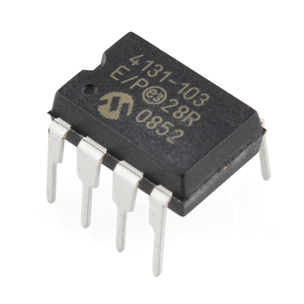
While useful, a digital potentiometer is significantly different from a mechanical one. Mechanical potentiometer are continuously variable, but digital ones are limited to a fixed number of resistance steps. Mechanical potentiometer can also handle significantly more power and wider voltage ranges than digital ones; it's pretty easy to overload a digital pot of this type. And digital pots do not automatically remember the setting. Some digital pots have memory a "non-volatile wiper", but not this one. From the picture it looks like this is a MCP4131, which is a low end model from the Microchip line. This model has only 129 selectable resistance steps. There are models with 257 steps, which gives you twice the resolution, and models that have non-volatile memory (both for the wiper and a few spare bytes that can come in handy). Also, if you are looking to control a stereo signal you should consider a dual potentiometer model because the pots will be more closely matched than if you use two single pot chips.
SFE editors: Ya might want to rebuild your search index - searching for "Digital Potentiometer" or "Potentiometer" doesn't find this product.
Just an FYI i bought some digital pots for audio. if your like me and want push button functionality you want a scale to go with this. using the wiper resistance i found dbGainMin to be~ -40db. now I get why digital audio seems to use a 40 digit scale, 1 per -db. the important thing is i cranked out the equation for software audio using db to voltage gain eq., voltage divider.This is assuming optimal settings for a 10K.(at low volumes the steps size of 1 is larger than the accuracy of an 8 bit version, not sure which this is. i get a percent precision around .39%) Rwb(%)=100%*10^(db/20)
hope this helps others. Please check my math. I haven't made near enough mistakes to be an expert. I chose to use a count from 0-40 so i included a - in the eq.
I am wanting to control the KIT-09612 with my arduino and do some cool stuff. Would it be possible to use this as the interface?
Found useful: (whole walkthrough) https://www.youtube.com/watch?v=_dUQOTemSJQ
Would 2 of these work well for line level volume control?
Why is this categorized in General rather than General ICs?
can i use it to control LED current? i can see in datasheet that: "Maximum current into PXA, PXW & PXB pins ............±2.5 mA" And a standard LED will need almost 20mA
After trying the various approaches outlined in the 3 year old comments, I found this very helpful video that should get you started if you are stumped like I was: https://www.youtube.com/watch?v=_dUQOTemSJQ
Would it be possible to use two of these digital potentiometers with one Arduino?
Should be. I recommend you follow this advice to make sure it's reliable.
MCP41HV51-103E/ST. Can withstand up to 36v on the resistor terminals
"...sweep profile.In other..."
you're missing the space between the period and "In"
I can't get this chip to work at ALL. I'm pretty experienced with SPI as well, so I'm really not sure WTF is happening. It's accepting my commands, because when I read back the status it's not giving me the error bit. So it's acknowledging that I'm giving it a valid address/command combination... but then it doesn't do anything! I've tried the 8-bit increment/decrement commands, plus the 16-bit write commands to try and set the wiper value, but nothing changes... anyone else having this problem?!? I'm using a Bus Pirate to interface with it. Perhaps I'll try using an ATmega or a PIC next
Looking for a tutorial on this part, all the links below seem to be dead.
For dead pages (or domains), I use the way back machine web site https://web.archive.org/web/. The cached copy of the uduino page is at https://web.archive.org/web/20130225145201/http://www.uduino.com/tutorials/1
I want to use d digital potentiometer MC4542 to increase and decrease the voltage of an appliance exactlly by 0.5 volts. also the voltage stage should remain same even after power cut. Can any one help me with the proceddure...I have to use this with pic12f675 to instruct the potentiometer.
btw, found this a lot simpler than what was in the comments. First line of the code got messed up...It should include the spi library header file.
http://www.uduino.com/tutorials/1
I took the Mighty Drake's library for Arduino (which is awesome) and modified it to work for LeafLab's Maple IDE/Controller if anyone is interested:
https://github.com/johnnyonthespot/MapleLibraries/tree/master/MCP4131
Has anyone tried or have an opinion on how well this pot would work replacing the mechanical pots on an xbox 360 controller? The resistance range of each axis on the thumbsticks seems to be about 10k-ish.
can these pot use in line following robot,.,. , any idea., to set the vref for white line
Can anyone post a circuit diagram for this? I'm a software guy and all these CS, SPI P0A stuff is confusing. Something similar to this one but specific to this chip: http://www.arduino.cc/en/Tutorial/SPIDigitalPot
Thanks! -- T
Does anybody have Eagle library for this chip?
it's just an 8-pin dip... use any similar 8-pin dip chip (like a microchip 24LS640 or something) and you'll have the exact same footprint.
Nevertheless, given that its SOT8 cousin is in the SFE libraries, can't hurt to add the DIL one :)
Does anybody have Eagle library for this chip?
Does anybody have Eagle library for this chip?
I have a problem with the shared MISO/FMOSI port. I tried it out with a board (GHI Panda2) with 5V power supply and it works fine with the 4.7K resistor. Then I tried with the GHI ChipWorkX which requires 3V3 as it isn't 5V tolerant and there I have some problems. Simply running the chip with 3V3 didn't work at all (I didn't get any reply). When I run the chip at 5V with Level converters (http://www.sparkfun.com/products/F8745) converting the SPI interface to 3V3 I don't get absolute values for the wiper but only values of 0, 1, 3, 7, 15, 31, 63 etc. Has anyone else seen this as well? Any idea how to run the chip natively at 3V3? I guess I just have to use another resistor instead of 4.7K but I tried all the resistors from the Resistor Kit (http://www.sparkfun.com/products/F10969) and the full range from the POTI itself but none seem to work neither on the Panda2 nor the CWX. Any help will be greatly appreciated!
Someone please do a Bildr post on this!!
Quick question regarding the usage of a digital potentiometer: Can you use another resistor or potentiometer or digital potentiometer in series or parallel to change the values as you would with a mechanical one, or is the variability of the digital version accomplished in such a way as to make this impossible?
Yes you can think of it as a regular ole POT.
Internally its just a bank of resistors in a ladder (http://en.wikipedia.org/wiki/Resistor_ladder) which are switched in and out to achieve the resistance requested over the SPI interface.
Here's a library that to use with this POT.
https://github.com/declanshanaghy/ArduinoLibraries/tree/master/MCP4161
I wrote it when i used an MCP4161 in a project of mine. The chip featured on this page is a 4131 but the protocol is the same, so the library should work. If not, you could tweak it to work for both chips and submit a pull request.
I tried your library but couldn't get it to work. You have MOSI and MISO set to different pins in the header, but the 4131 seems to have merged them to 1 pin.
The 8-lead Single Potentiometer devices are pin limited so the SDO pin is multiplexed with the SDI pin
(SDI/SDO pin). After the Address/Command (first 6-bits) are received, If a valid Read command has been
requested, the SDO pin starts driving the requested read data onto the SDI/SDO pin.
Can you provide an implementation of your library? Or can anyone else point me in the right direction? I know as much about SPI, well lets just say I know that i do not know.
http://www.drakescomputers.com/arduino/MCP4131.zip
I ran into the same problem, Tinkered and got it to work. You will need a resister...
According to the datasheet, a simple resistor can be used to convert your existing MOSI/MISO lines into multiplexed 1 wire version. Which is good news as I wanted them to share the same SPI lines as everything else one that bus.
I used a 4.7k resistor on the SDO line, to multiplex them together (based on the datasheet)...seems to somewhat work. I got the wiper to wipe in both directions. Some how the read command isn't working for me though...